iM3 REVOLUTION 4DC User manual

97050901
REF 97050914
Rev. 00
17.02
REVOLUTION 4DC
EN

2
OPERATOR'S MANUAL
EN
ITALIANO

EN
OPERATOR'S MANUAL
3
Contents
1. GENERAL WARNINGS.............................................................................................................................................5
1.1. SYMBOLS ............................................................................................................................................................5
1.2. STANDARDS AND REGULATIONS ....................................................................................................................6
1.3. INTENDED USE ...................................................................................................................................................6
1.4. CLASSIFICATION ................................................................................................................................................6
1.5. ENVIRONMENTAL CONDITIONS .......................................................................................................................7
1.6. WARRANTY .........................................................................................................................................................7
1.7. PROTECTION AGAINST RADIATION ................................................................................................................8
2. DESCRIPTION OF THE X-RAY DEVICE .................................................................................................................9
2.1. INSTALLATION TYPE..........................................................................................................................................9
2.2. TYPE OF X-RAY HEAD .....................................................................................................................................12
2.3. HANDHELD ........................................................................................................................................................12
3. SWITCHING ON AND OFF THE X-RAY DEVICE ..................................................................................................13
4. HANDHELD FUNCTIONS.......................................................................................................................................14
4.1. HANDHELD DISPLAY FUNCTIONS..................................................................................................................15
4.2. USE OF HANDHELD .........................................................................................................................................16
4.3. CHECKING THE PARAMETERS.......................................................................................................................17
4.4. FACTORY SETTINGS .......................................................................................................................................18
5. USE OF THE X-RAY DEVICE.................................................................................................................................19
5.1. PATIENT POSITIONING....................................................................................................................................19
5.2. POSITIONING THE X-RAY HEAD.....................................................................................................................19
5.3. POSITION OF THE X-RAY PLATE OR SENSOR .............................................................................................20
5.4. SETTING THE EXPOSURE MODE AND TIME.................................................................................................21
5.5. PROCEDURE TO BE FOLLOWED WHEN TAKING THE X-RAY.....................................................................23
6. ADVANCED OPTIONS ...........................................................................................................................................24
6.1. SETTING THE OPERATING MODE..................................................................................................................25
6.2. SETTING TYPE OF MOVABLE COLLIMATOR.................................................................................................26
6.3. RESTORING FACTORY SETTINGS .................................................................................................................26
7. ERROR MESSAGES ..............................................................................................................................................27
8. PERIODIC MAINTENANCE ....................................................................................................................................28
9. CLEANING AND DISINFECTION ...........................................................................................................................29
10. DISPOSING THE EQUIPMENT WHEN NO LONGER USED ................................................................................30
11. TECHNICAL DATA..................................................................................................................................................31
11.1. X-RAY TUBES ...............................................................................................................................................33
11.2. TECHNICAL FACTOR MEASURE ................................................................................................................34
12. DIMENSIONAL CHARACTERISTICS.....................................................................................................................35
13. IDENTIFICATION PLATES .....................................................................................................................................38
14. TIMES/SENSITIVITY CHARTS...............................................................................................................................40
15. NOMINAL DOSE EMISSION VALUES ...................................................................................................................41
16. INSPECTION AND MAINTENANCE.......................................................................................................................51
16.1. USER INSPECTION ......................................................................................................................................51
16.2. TECHNICAL MAINTENANCE........................................................................................................................52

4
OPERATOR'S MANUAL
EN
EN
OPERATOR'S MANUAL
5
1. GENERAL WARNINGS
These instructions explain how to correctly use the REVOLUTION 4DC x-ray unit. Please carefully read this manual
before using the device.
NOTE: This manual does not specify all the obligations and warnings for possessing a source of ionising
radiation as each country has its own laws. Only the most common ones shall be mentioned and this means
that it is the user’s responsibility to check local standards and observe the relevant laws.
This publication must not be reproduced, copied or transferred in any manner (electronically, mechanically, via
photocopies, translations or other means) without the prior written consent of the manufacturer.
The manufacturer has a company policy of continual development. Therefore, some of the instructions, specifications
and figures given in this manual may slightly differ from the purchased product. The manufacturer reserves the right
to make changes to this manual without giving prior notice.
The original text is in Italian.
Please consult the Web site of the manufacturer to find a list of authorised representatives.
1.1. SYMBOLS
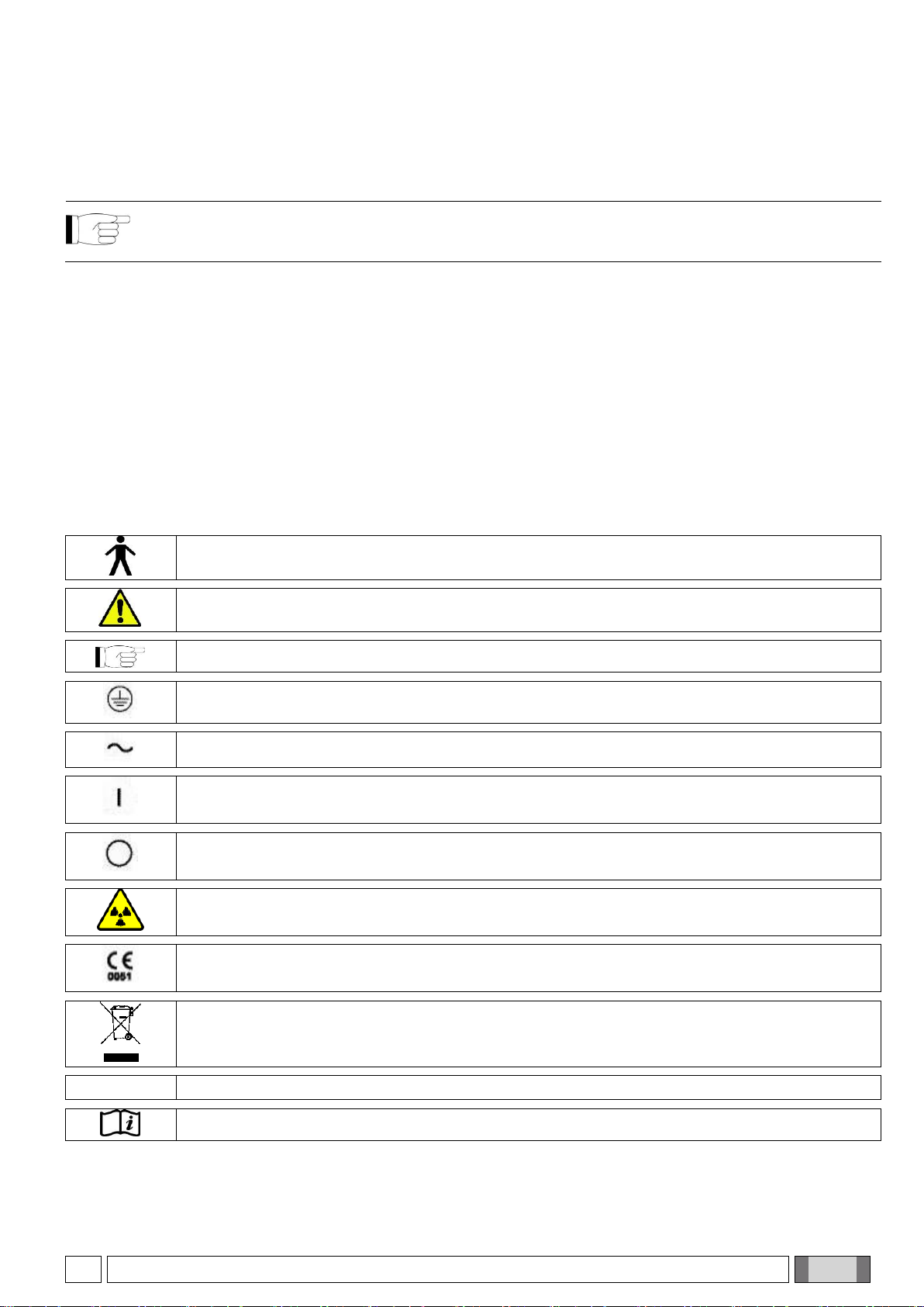
Type of protection against direct and indirect contact: Class I. Level of protection against direct and
indirect contact: TYPE B.
WARNING! Failure to observe may result in equipment damage or injury to the user and/or patient.
NOTE: Indicates information that is especially important for the user and/or assistant.
Protective ground contact.
Alternating current.
On.
Off.
Ionising radiations.
Equipment in compliance with essential requirements of directive 93/42/EEC and subsequent
changes.
Disposal symbol in accordance with Directives 2002/95/EC and 2003/108/ EC.
FCC ID
F.C.C. mark (Federal Communication Commission).
Operating instructions. Consult the enclosed documentation before using the device.

6
OPERATOR'S MANUAL
EN
It is necessary to refer to the user manual.
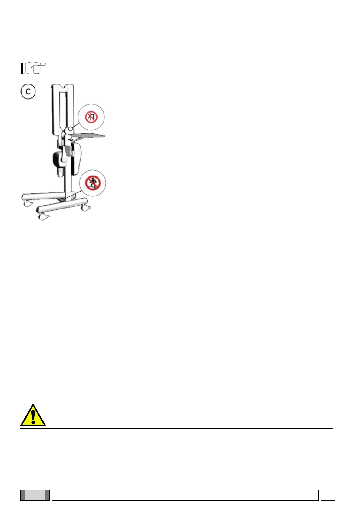
Pushing prohibited.
Stepping prohibited.
UA.TR.101
Ukrainian national symbol of conformity.
1.2. STANDARDS AND REGULATIONS
The system has been designed to meet the following standards:
- Directive 93/42/EEC and s.c. (dir. 2007/47/EC) - Medical Device Directive;
Technical Standards:
IEC 60601-1:2005
IEC 60601-1-2:2007
IEC 60601-1-3:2008
IEC 60601-2-65:2012
IEC 60601-1-6:2010
IEC 62366:2008
The CE marking certifies compliance of the product as described by Medical Device Directive 93/42/EEC and
subsequent amendments.
1.3. INTENDED USE
This x-ray unit is designed for use in the dental surgery to make endo-oral x-rays for diagnostic purposes.
This equipment can be used to produce traditional x-rays developed using chemicals or, alternatively, it can be used
with digital x-ray sensors.
1.4. CLASSIFICATION
- MEDICAL DEVICE classification.
Classification of the equipment according to the rules indicated in Annex IX of Directive 93/42/EEC and
subsequent changes: CLASS IIB.
- ELECTRO-MEDICAL EQUIPMENT classification.
Equipment classification in accordance with standard I.E.C. 60601-1 for safety of medical equipment: CLASS I
TYPE B, not continuous use.
- RADIO EQUIPMENT AND TELECOMMUNICATIONS TERMINAL EQUIPMENT classification.
Equipment classification according to Directive 99/05/EC Art.12: CLASS I.
- EMC classification.
Equipment classification in accordance with standard CEI EN 55011: GROUP I TYPE B.

EN
OPERATOR'S MANUAL
7
1.5. ENVIRONMENTAL CONDITIONS
The equipment is to be installed in rooms that satisfy the following requirements:
- Temperature from +10 to +40° C.
- Relative humidity from 25 to 75% without condensate.
- Atmospheric pressure from 700 to 1060 hPa.
The electrical wiring in the room in which the equipment is installed must conform to I.E.C. 60364-7-710;V2
specification (i.e. the regulations concerning the electrical wiring to be used in surgeries) or equivalent standards
in force in the country where the equipment is installed.
- ELECTRICAL CONNECTIONS: the electrical system must be provided with an adequate grounding system that
complies with regulations I.E.C. - US National Electrical Code and C.E.I.. In Italy, it must be executed in
accordance with IEC 60364-7-710, which requires a differential-thermal breaker with the following characteristics
upstream of the system:
- contact capacity: 250V 10° or 120V 16A in compliance with standards IEC 60898-1 and IEC 60947-2;
- differential sensitivity: 0.03A;
- power supply: 3x2.5 mm2.
The colour of the 3 wires should be as specified in the standards (BROWN power, BLUE neutral, YELLOW/GREEN
ground).
1.6. WARRANTY
The manufacturer stands behind its products warranting safety, reliability and performance. The warranty is valid only
under the following terms:
- Closely observe the conditions specified in the warranty certificate itself.
- The equipment is only to be used as instructed in this manual.
- Equipment installation, expansion and technical support must be performed exclusively by personnel authorised
by the manufacturer to carry out these operations.
- Never open the equipment casing. Installation, repairs and, in general, any other operations requiring the casing
to be opened are to be performed exclusively by personnel authorised by the manufacturer to carry out these
operations.
- The equipment is to be installed in rooms that follow the requirements specified in paragraph 1.2.2.
“Environmental conditions”.
- The room where the x-ray unit is installed must comply with official regulations regarding protection against
radiation in the country where the equipment is used.
SAFETY WARNINGS.
- If any person who is not an authorised technician changes the product in any way by replacing parts or
components with other ones not used by the manufacturer, they shall assume responsibility for the
product.
- Do not forget to turn off the main switch on the equipment before leaving the surgery.
- The equipment is not protected against liquid penetration (risk of electrocution).
- The equipment is not suitable for use in the presence of a mixture of flammable anaesthetic gas with
oxygen or nitrous oxide.
- This equipment must be stored properly so that it is kept in top working order at all times.
- Use of electric scalpels or other electric apparatus that do not comply with standard I.E.C. 60601-1-2, in
the surgery or nearby may cause electromagnetic or other types of interferences resulting in equipment
malfunctions. In these cases shut off the power supply to the equipment beforehand.
- The manufacturer shall not be held responsible for misuse, carelessness or improper use of the
equipment.
- The equipment may only be used by authorised and adequately trained staff (dentists and paramedics).
- The user must be present at all times when the equipment is turned on or ready for start-up. In
particular, never leave the equipment unattended in the presence of children/the mentally disabled or
other unauthorised personnel in general.
- If the x-ray equipment is damaged or oil leaks, do not use the equipment and contact customer service
immediately.

8
OPERATOR'S MANUAL
EN
1.7. PROTECTION AGAINST RADIATION
PROTECTION AGAINST RADIATIONS.
X-rays are hazardous and adequate precautions must be taken when using them. Areas where it is possible
to be exposed to x-rays shall be clearly indicated by using this symbol, which should remind personnel to
observe the safety rules laid down by the laws in force in the country where the equipment is used.
- Control the emission of x-rays from the greatest distance possible (at least 2 meters) from the focal spot
and the x-ray irradiation beam in the opposite direction to where the rays are emitted. For installations in
Canada, the required distance is 3 meters.
- Only the authorised personnel and the patient can remain in the room when x-rays are being emitted.
- The device is provided with an interlock input. If the interlock is activated, it means that the door is open
while the examination is in progress and the ray emission is inhibited. To proceed with the examination,
close the door.
- Make sure that the operator can communicate verbally and visually with the patient during the
examination.
- As for the installation, please refer to the Technical Manual.
- Always protect the patient’s thyroid and gonads under all circumstances.
-Whenever the patient is a child or disabled person requiring the presence of the dentist to keep the
image receiver in position, it is advisable to use a positioner, following the instructions of the
manufacturer of the receiver, and a special glove to protect the hand against x-rays. Use a suitable
overall to protect the rest of the body against exposure to x-rays.
EN
OPERATOR'S MANUAL
9
2. DESCRIPTION OF THE X-RAY DEVICE
The x-ray unit is available in several versions, which differ in type of installation, x-ray head and handheld.
It is possible to identify the different versions via the REF on the nameplate.
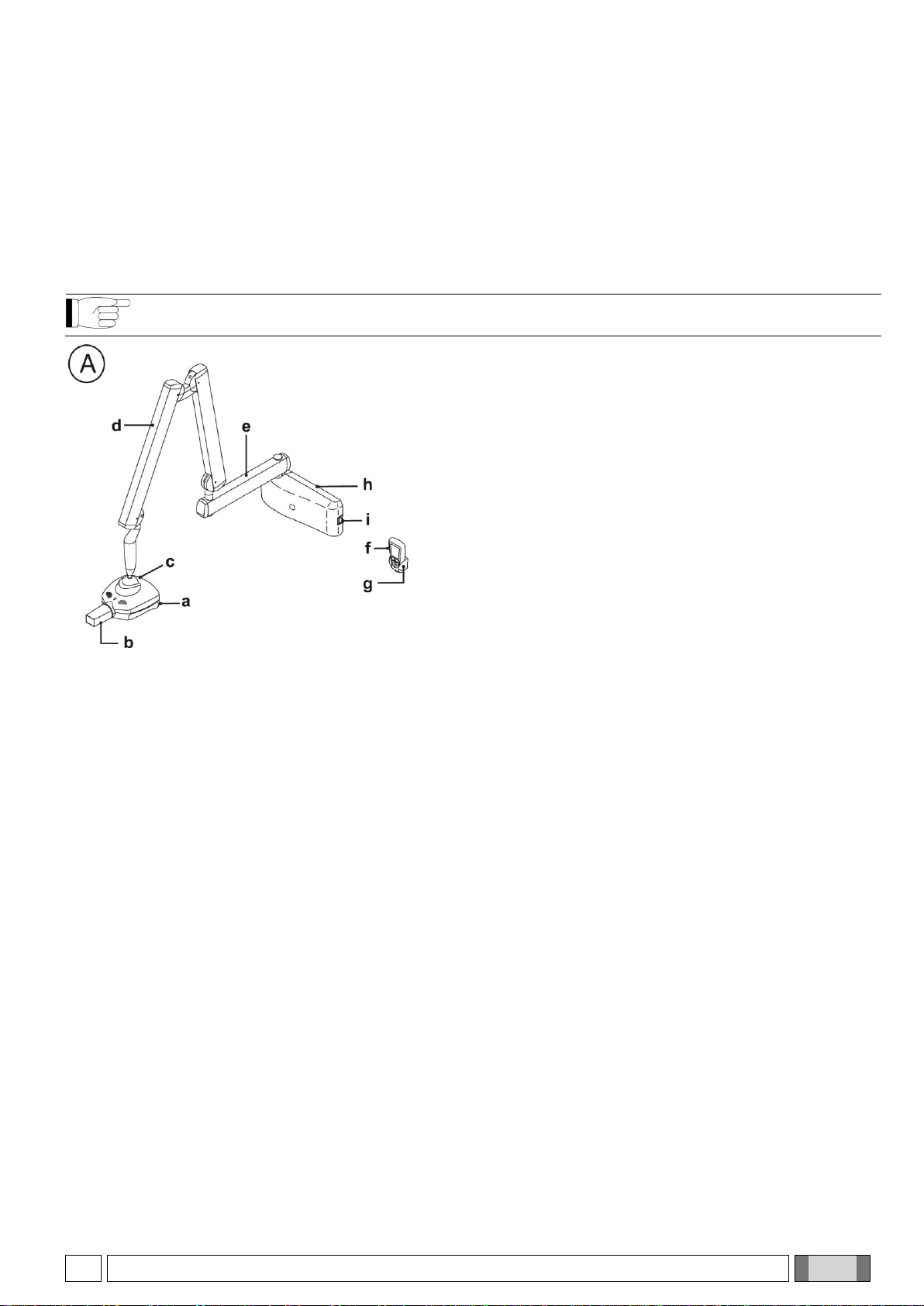
2.1. INSTALLATION TYPE
WALL-MOUNTED VERSION
NOTE: This section applies only to models RX DC REF: I3PV****S
(Character * can be any alphanumeric value)
a. X-ray generator.
Constant potential high frequency x-ray generator.
b. Removable collimator (cone).
The generator can work with different types of collimator that are automatically recognised:
- 8” cylindrical COLLIMATOR (incorporated in the generator): minimum skin/focus distance 20cm and 60mm
output beam.
- removable 12” rectangular COLLIMATOR (only for I3PV****S): minimum skin/focus distance 30cm and 45x35
mm output beam (rectangular collimator attached).
- removable 12” round COLLIMATOR (optional for I3PV****S): minimum source/skin distance 30cm and diameter
of collimator output beam 55mm (with collimator attached).
The following rectangular collimators to be attached to a 12” round collimator are also available as optionals:
- rectangular COLLIMATOR 22x35 mm
- rectangular COLLIMATOR 31x41 mm.
c. Focus spot.
d. Double pantograph arm.
e. Extension arm.
The extension arm is available in three length versions: 40 cm (15.7"), 60 cm (23.6") and 90 cm (35.4").
f. Handheld.
The handheld can be placed either near the control unit or in a remote position. As a result, the doctor can move
conveniently around the room and move out of the area where x-rays are emitted.
g. Handheld holder.
h. Control unit.
I - Main switch.
10
OPERATOR'S MANUAL
EN
MOBILE STAND INSTALLATION
NOTE: This section applies only to models RX DC REF: I3PV****M
(Character * can be any alphanumeric value)
c. X-ray generator.
Constant potential high frequency x-ray generator.
d. Removable collimator (cone).
The generator can work with different types of collimator that are automatically recognised:
- 8” cylindrical COLLIMATOR (incorporated in the generator): minimum skin/focus distance 20cm and 60mm
output beam.
- REMOVABLE 12” rectangular COLLIMATOR (only for I3PV****M): minimum skin/focus distance 30cm and
45x35 mm output beam (rectangular collimator attached).
- REMOVABLE 12” ROUND COLLIMATOR (optional for I3PV****M): minimum source/skin distance 30cm and
diameter of collimator output beam 55mm (with collimator attached).
The following rectangular collimators to be attached to a 12” round collimator are also available as optionals:
- RECTANGULAR COLLIMATOR 22x35 mm
- RECTANGULAR COLLIMATOR 31x41 mm.
c. Focus spot.
d. Double pantograph arm.
e. Handheld.
The handheld can be placed either near the control unit or in a remote position. As a result, the doctor can move
conveniently around the room and move out of the area where x-rays are emitted.
f. Handheld holder.
g. Control unit.
h. Main switch.
WARNING!
Never move the mobile stand x-ray unit without first securing the support arm with the special strap.

EN
OPERATOR'S MANUAL
11
To move the mobile stand x-ray unit:
1) Unplug the x-ray unit power cord from the power supply.
2) Place the power cord so that it does not get in the way.
3) Always secure the support arm with the associated safety belt.
4) Move the x-ray unit carefully using the handles.
WARNING!
Moving the mobile stand x-ray unit without using the handles can cause the device to fall, unbalance or tip
over. Be very careful and always use the handles.
WARNING!
During the movement of the mobile stand, pay attention to the presence of steps and / or horizontal
obstacles as they may cause a situation of instability and / or tip over the cart. If you wish to move the x-
ray over a small obstacle, gently tilt the base by pressing with your foot near the rear wheels.
WARNING!
The tray can hold a maximum of 5kg.
WARNING!
Do not step on the mobile stand or parts of it.
To stop the mobile stand in the desired position, lock the wheel brakes by pressing the lever down. Upwards to
unlock.
NOTE: always lock at least two brakes to avoid unwanted movements.
12
OPERATOR'S MANUAL
EN
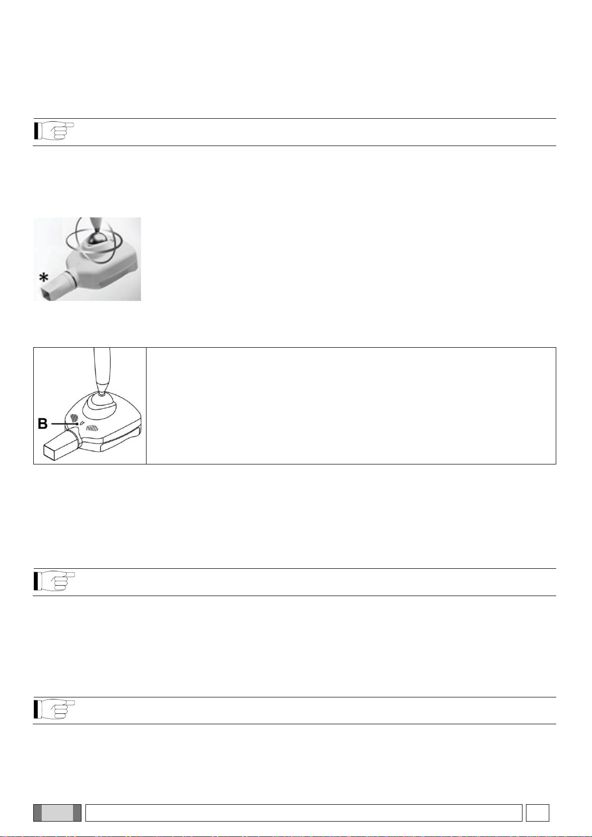
2.2. TYPE OF X-RAY HEAD
X-RAY HEAD WITH BALL JOINT
NOTE: This section applies only to models RX DC REF: I3PV*****
(Character * can be any alphanumeric value)
The mechanical fitting with which the x-ray head is connected to the pantograph arm is a ball joint. The ball is
provided with a mechanical brake to allow the x-ray head to maintain the position set by the operator.
The generator can freely rotate on the horizontal plane. On the vertical plane, the upward rotation is limited by a
mechanical end stop.
The cone, indicated with *, is the only applied part
X-RAY GENERATOR INDICATOR LIGHT FOR X-RAY UNIT WITH BALL JOINT:
The x-ray generator is provided with an indicator light (B) that signals the unit status.
Key to colours:
- violet > x-ray unit on (regular condition)
- flashing violet > stand-by (low consumption)
- blue > x-ray unit on –head locked
- yellow > x-ray being emitted
- red > fault
2.3. HANDHELD
The handheld is turned on by pressing any key, except for the one for x-ray emission.
WIRELESS HANDHELD
NOTE: This section applies only to models RX DC REF: I3PV***W*
(Character * can be any alphanumeric value)
This handheld uses a wireless connection to communicate with the x-ray unit.
The wireless communication complies with specifications IEEE 802.11 b/g/n. The connection is protected through
cryptography and no other wireless product, except for the handheld, can connect to the unit.
Handheld batteries:
- Type: 2 x AA - Alkaline 1.5V.
WIRED HANDHELD
NOTE: This section applies only to models RX DC REF: I3PV***C*
(Character * can be any alphanumeric value)
This handheld uses a cable connection to communicate with the x-ray unit.

EN
OPERATOR'S MANUAL
13
3. SWITCHING ON AND OFF THE X-RAY DEVICE
TURNING ON THE WALL-MOUNTED X-RAY UNIT
NOTE: This section applies only to models RX DC REF: I3PV****S
(Character * can be any alphanumeric value)
The control unit is turned on and off from the main switch
(A).
The switch lights up to indicate that the control unit is
powered.
TURNING ON THE MOBILE STAND X-RAY UNIT
NOTE: This section applies only to models RX DC REF: I3PV****M
(Character * can be any alphanumeric value)
The control unit is turned on and off from the main switch
(A).
The switch lights up to indicate that the control unit is
powered.
NOTE: The technical specifications of the switch are outlined in paragraph 1.5.
Whenever turned on, the equipment performs an operational test that takes a few seconds. A beep is
emitted at the end of the test.
NOTE: The exposure time and the parameters displayed on the handheld when the unit is turned on are the
last ones set before the control unit was turned off.
If the control unit is left untouched for a few minutes, it will go into standby mode. Simply press any key on
the control panel to reactivate it.
14
OPERATOR'S MANUAL
EN
4. HANDHELD FUNCTIONS
The handheld is turned on by pressing any key, except for the one for x-ray emission.
A buzzer rings to confirm that the unit has been turned on. The unit will be in the standard configuration and it will
start searching for the base it works with.
If the base is off, the handheld will not indicate the field or the status “ready”. If the base is later turned on, the
handheld will detect it within thirty seconds or by pressing any function key on the push-button panel.
NOTE: To optimise the range of the handheld while it is being used, keep it away from walls and metal
instruments and, above all, do not cover its built-in antenna on top of the screen. In addition, performance
may be reduced if the handheld is moved too quickly while x-rays are being taken. Error E 31 may be
displayed if out of range problems occur.
WIRELESS HANDHELD
NOTE: This section applies only to models RX DC REF: I3PV***W*
(Character * can be any alphanumeric value)
AUTOMATIC HANDHELD SHUT OFF:
Once the control unit has been turned off, the handheld automatically shuts off after approximately one minute.
The handheld also automatically shuts off when it is at a further distance from the maximum range of the control until.
HANDHELD TIMED STAND-BY:
The entire x-ray unit will switch over to stand-by (even if the base is on) and the handheld will automatically shut off
after approximately five minutes of non-use to save battery power.
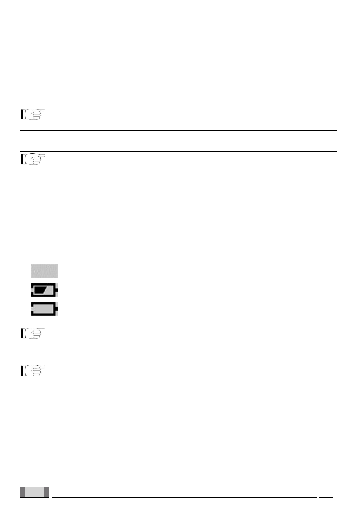
BATTERIES AND CHARGE LEVEL INDICATION:
The handheld runs on two standard AA alkaline batteries to assure sufficient stand-alone operation.
The charge level of the batteries is shown on the screen as follows:
Battery fully charged (no symbol appears in the area that shows the battery charge level).
Battery half-charged.
Battery charge level low or almost dead (causing the handheld to automatically shut off).
NOTE: The batteries should be removed from the handheld if it is not going to be used for an extended
period.
WIRED HANDHELD
NOTE: This section applies only to models RX DC REF: I3PV***C*
(Character * can be any alphanumeric value)
AUTOMATIC HANDHELD SHUT OFF:
The handheld will automatically turn off after switching off the control unit.

EN
OPERATOR'S MANUAL
15
4.1. HANDHELD DISPLAY FUNCTIONS
1
Field present for dialoguing with “base”
2
Pause for cooling
3
Handheld identification number
4
Memorising
5
Battery status
6
Patient size selection
7
8” round collimator on (12” rectangular collimator not attached)
8
Interlock active
9
Graduated bar for thermal load
10
Time/dose unit of measure
11
Exposure time and dose display
12
Tooth selection

16
OPERATOR'S MANUAL
EN
4.2. USE OF HANDHELD
As illustrated in the figure below, the handheld has four function keys and a single x-ray emission key.
1
“Dentition area selection” key
2
“Body size selection” key
3
X-ray emission light
4
“Increase” key
5
“Decrease” key
6
“X-ray emission” key
The main functions of the keys on the handheld, depending on how they are pressed, are:
KEY
BRIEFLY PRESSED (less than 3 sec.).
PRESSED LONGER (more than 3 sec.).
Changes over from LARGE to SMALL and
vice versa (takes place when key is released).
Saves the selected setting (exposure time,
sensitivity, etc…). The memo icon ( ) lights up
when the data item can be saved.
Selects the various types of teeth to choose
the area to be examined.
Displays the values corresponding to the tooth
exposure times in mGy and in mGy*cm2if
pressed again.
Increases the exposure times in steps
according to the set scale.
Increases the scroll speed of the values in
increasing order.
Decreases the exposure times in steps
according to the set scale.
Increases the scroll speed of the values in
decreasing order.
NO EFFECTS ARE OBTAINED IF THE KEY
IS PRESSED FOR LESS THAN A SECOND.
Starts x-ray exposure (the button has to be held
down throughout the x-rays emission, “dead man”
function).
NOTE: “Dead man” function: the system that starts x-ray exposure with the dedicated key on the wireless
handheld allows x-rays to be emitted only when the user presses and holds down the exposure key. X-ray
emission will stop if the key is released ahead of time.
EN
OPERATOR'S MANUAL
17
NOTE: The function related to pressing the key briefly is performed by pressing the key which will activate
the function assigned to it. On the other hand, to perform the function carried out when the key is held down
longer, press the key until the relative function is started. The buzzer will beep shortly to signal that the
function has been activated.
NOTE: Warm-up: When the equipment has not been used for a prolonged period (more than 3 months) or
when turned on for the first time, it is advisable to perform a series of emissions with short times (0.01-0.02
sec.) and then, progressively, some pictures with 0.1 sec. intervals to better stabilise the operation of the x-
ray tube before using it.
4.3. CHECKING THE PARAMETERS
Before actually taking an exposure, make sure that the exposure parameters for the examination in progress are
correctly set:
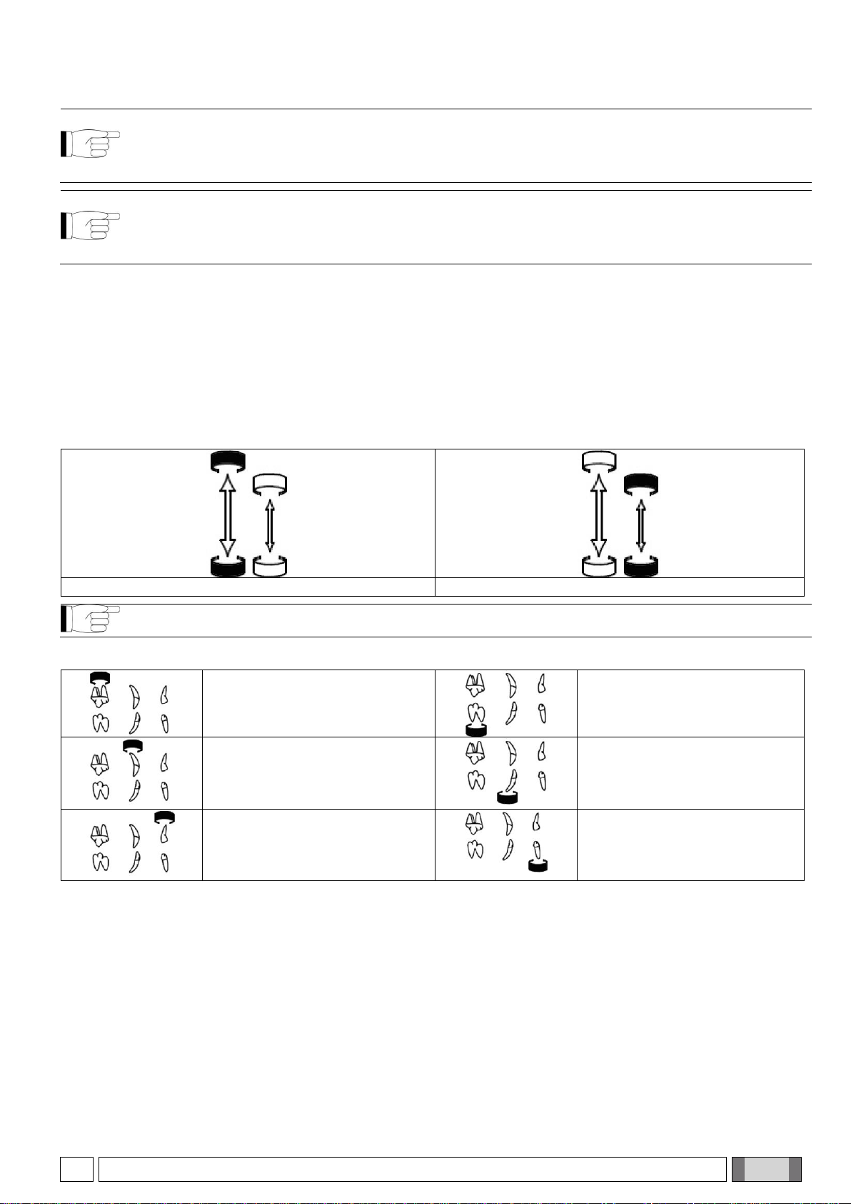
- Checking the selected patient size.
- “SMALL” symbol selected: indicates that the x-ray unit is set for patients with small builds.
- “LARGE” symbol selected: indicates that the x-ray unit is set for patients with average-large builds.
Average/large build (LARGE) selected
Small build (SMALL) selected
NOTE: After the change has been made, the preset exposure times will automatically be modified.
- Checking the selected type of intraoral exam.
Upper molars exam
Lower incisors exam
Upper canines/bicuspids or rear
“bite-wing” exam
Lower canines/bicuspids exam
Upper incisors
or front “bitewing” exam
Lower molars exam

18
OPERATOR'S MANUAL
EN
4.4. FACTORY SETTINGS
REVOLUTION 4DC x-ray unit is supplied with the following factory settings:
- Operative mode: AUTO.
- Sensitivity: level 19.
- Handheld stand-by: 5 minutes
- Exposure times as per standard R'20: 0.020 - 0.022 - 0.025 - 0.028 - 0.032 - 0.036 - 0.040 - 0.045 - 0.050 - 0.056
- 0.063 - 0.071 - 0.080 - 0.090 - 0.100 - 0.110 - 0.125 - 0.140 - 0.160 - 0.180 - 0.200 - 0.220 - 0.250 - 0.280 -
0.320 - 0.360 - 0.400 - 0.500 - 0.560 - 0.630 - 0.710 - 0.800 - 0.900 - 1.000
NOTE: These times comply with current standards I.E.C. 60601-1-3:2008 and the ISO 497 series R’20
recommendations and CANNOT BE MODIFIED.
EN
OPERATOR'S MANUAL
19
5. USE OF THE X-RAY DEVICE
5.1. PATIENT POSITIONING
A positioner or alignment device specific for the selected image receiver should always be used to assure the x-rays
are correctly aligned regardless of the position the patient’s head is in.
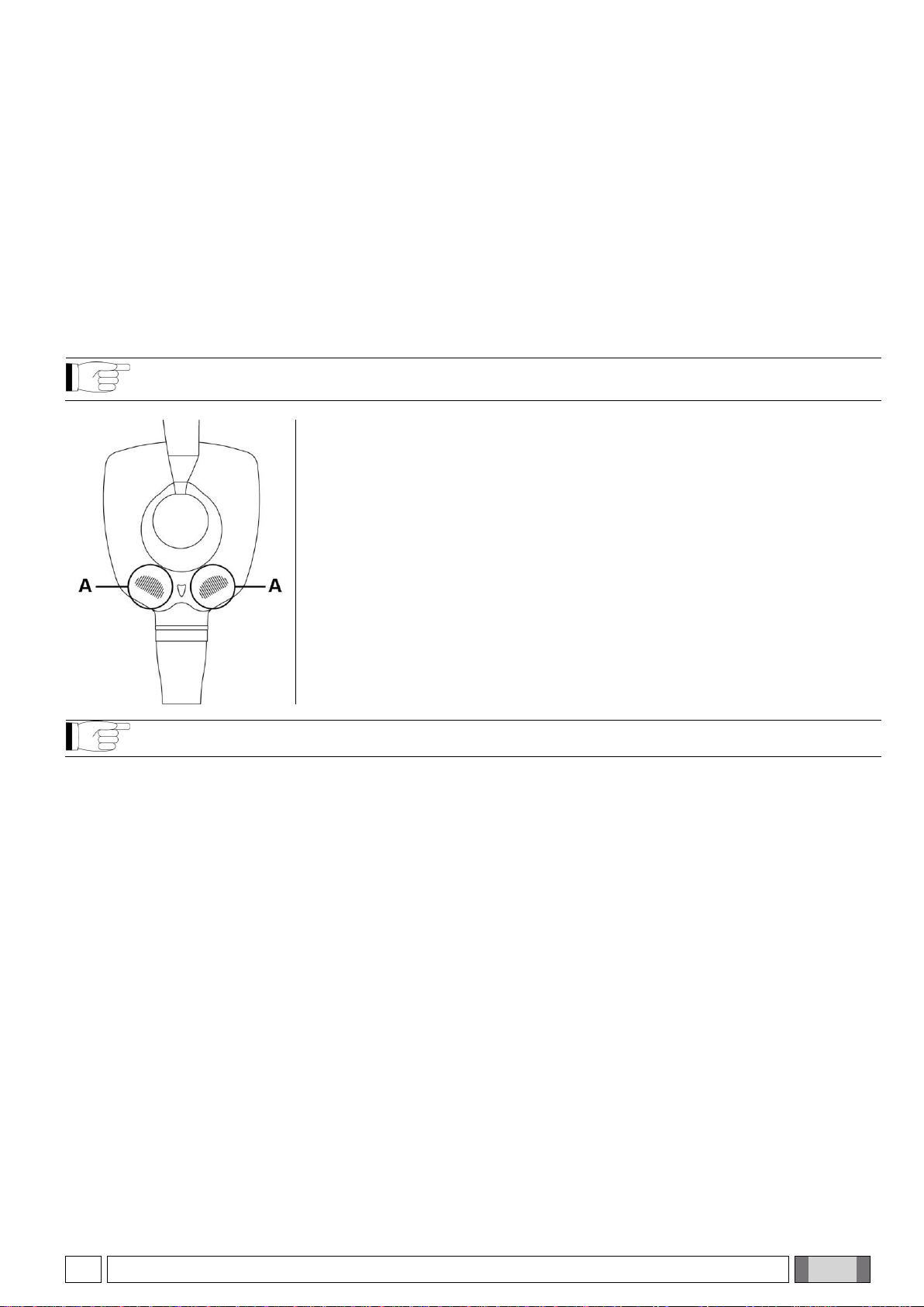
5.2. POSITIONING THE X-RAY HEAD
Position the x-ray head so that the cone is aligned with the image receiver.
BALL JOINT TECHNOLOGY
NOTE: This section applies only to models RX DC REF: I3PV*****
(Character * can be any alphanumeric value)
In the versions equipped with ball joint, the x-ray head can freely rotate on both its
horizontal and vertical axis.
An electromechanical brake initially locks the x-ray head. To release the head
and let it rotate on the positioning ball, work on the touch sensitive unlocking
areas located on it (see points A in the figure on the side).
Touching the unlocking areas allows positioning the x-ray head at the desired
angle to perform the exposure. To lock it again, simply release the unlocking
areas.
NOTE: Firmly hold the x-ray head with both hands when putting it in place.
It is possible to set a safety unlocking mode that allows the head to be turned only by pressing both unlocking
buttons. This prevents the head from unlocking unexpectedly after one of the two unlocking buttons has been
accidentally pressed. To activate this mode, refer to section 5 “Advanced options”.
20
OPERATOR'S MANUAL
EN
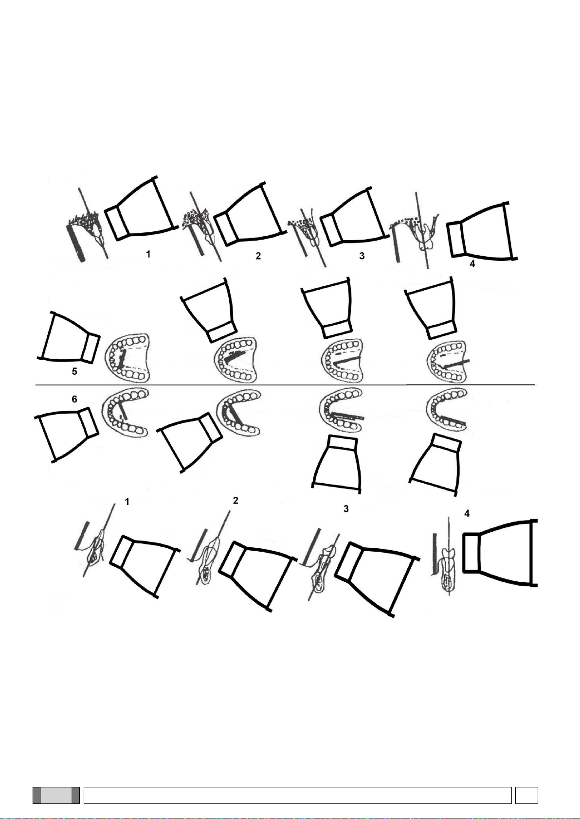
5.3. POSITION OF THE X-RAY PLATE OR SENSOR
The parallel technique, where applicable, provides more accurate images in terms of size compared to the bisecting
technique. A rectangular collimator, with 30 cm (12"), focus-skin distance, is always preferable to obtain better quality
pictures. To avoid exposing the image receiver only partly (whether it is a sensor or photostimulable phosphorus
plate system) an alignment device that gives rectangular collimators guidelines should be used. These lines are
usually given on the alignment ring.
- Parallel technique.
1
Incisors
2
Canines
3
Premolars
4
Molars
5
Upper arch
6
Lower arch
Other manuals for REVOLUTION 4DC
2
Table of contents
Other iM3 Dental Equipment manuals


