Direct Healthcare Services Mercury Advance SMARTcare User manual
DIRECTHEALTHCAREGROUP.COM
Service Manual

DIRECTHEALTHCAREGROUP.COM
2
MERCURY ADVANCE SMARTCARE

DIRECTHEALTHCAREGROUP.COM
SERVICE MANUAL
3
The Mercury Advance SMARTcare is a pressure relieving mattress suitable for use with patients at VERY HIGH RISK of pressure
ulcer damage.
Offering high levels of patient comfort, this unique system has the facility to “step up” to that of a dynamic mattress when clinically
required. Similarly, the mattress’s function can be downgraded as the patient’s condition improves.
These features make it particularly beneficial for use within the patient’s home or palliative care environment and help reduce
logistic and decontamination costs. The clinical benefits of a single system are equally applicable to those of a modern hospital
setting. A higher maximum weight capacity, up to 40 stone / 254kg, allows the product to meet the modern challenges of those
heavier clients. All component parts are interchangeable and replaceable, maximising product life and reducing environmental
impact.
1. Introduction .....................................................................................................................................................................4
2. Quick Reference Guide & Frequently Used Functions............................................................................................................4
3. Troubleshooting ...............................................................................................................................................................6
4. Installation .......................................................................................................................................................................7
5. Operation .........................................................................................................................................................................7
6. Transportation ..................................................................................................................................................................8
7. Warnings .........................................................................................................................................................................8
8. Maintenance Procedures...................................................................................................................................................9
9. Technical Specification ...................................................................................................................................................16
10. Technical Data..............................................................................................................................................................18
11. Optimum Conditions for Use ...........................................................................................................................................18
12. Symbols Guide & Contraindications for Use .....................................................................................................................18
13. Detachable / Removable Parts .......................................................................................................................................19
14. Disposal ......................................................................................................................................................................19
Contents
The new generation hybrid support surface
DIRECTHEALTHCAREGROUP.COM
4
MERCURY ADVANCE SMARTCARE
1. Introduction
Mercury Advance SMARTcare is an innovative solution in the prevention and treatment of pressure
ulcers. It offers effective dual therapy in a single surface by combining advanced, clinically proven
technologies previously only available in separate hybrid surfaces. Advanced air displacement
technology incorporated into a unique 4 zone configuration now provides more effective pressure
redistribution.
When used in non-powered mode, clinically proven advanced air displacement technology
continually optimises and improves pressure redistribution in response to patient body weight and
movement. The unique ‘air only’ heel zone effectively offloads pressure on the vulnerable heel area.
When used in powered/dynamic mode Mercury Advance SMARTcare delivers pressure relief via
a series of connected alternating foam and air cells. Unencumbered by a top layer of foam on the
mattress, the unique ‘foam in air cell’ construction ensures the delivery of effective pressure relieving
therapy. Dependant on clinical judgement, the alternating function can be operated on either a Low or
High Pressure
The digital Control Unit controls air flow into, or out of the air cells as required according to the
selected operating mode. It also maintains the air pressure within the mattress at the required level
and controls the action of the Audible/Visual Warning System in the event of mains supply failure or
over or under inflation pressure.
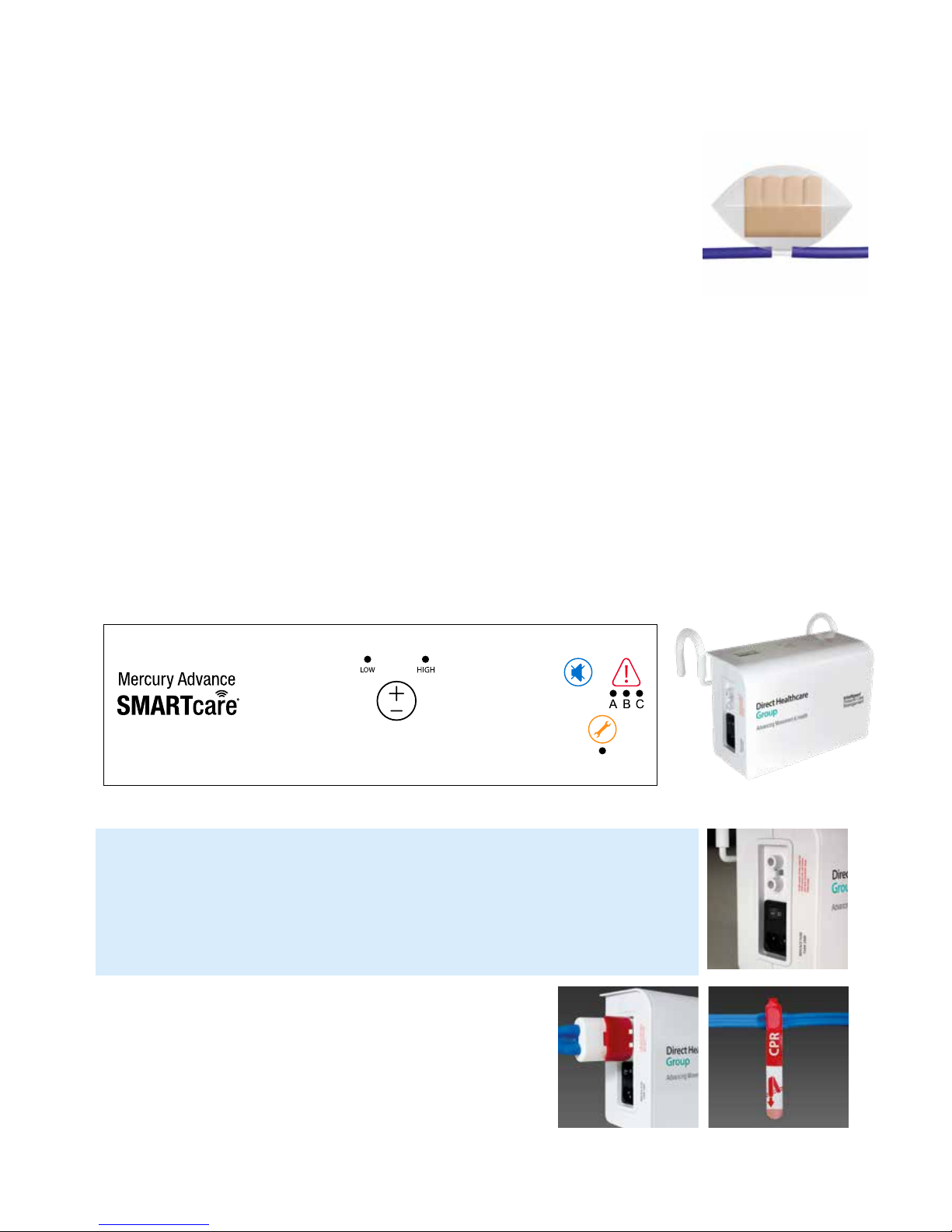
2. Quick Reference Guide (Frequently used functions)
This is a quick reference guide for the Mercury Advance SMARTcare System
Product Code MAT1610001
Power Switch Audible Warning Reset
The power switch simply switches the mains power to the Control Unit on and off.
When the Control Unit detects an Audible Warning condition, this can be silenced (see page 5)
and re-set by switching the Control Unit off and then back on again.
CPR Tag and Dual Function Connector
Please ensure that both the CPR Tag located on the umbilical and the Dual
Function Connector are always placed fully home, prior to inflating the mattress.
NB: The mattress will NOT inflate properly should this not be the case.
The CPR Tag is only to be used in the event of a clinical emergency for priority use.
However, disconnecting this function will rapidly deflate air from the mattress
in readiness for transport / static mode.
DIRECTHEALTHCAREGROUP.COM
SERVICE MANUAL
5
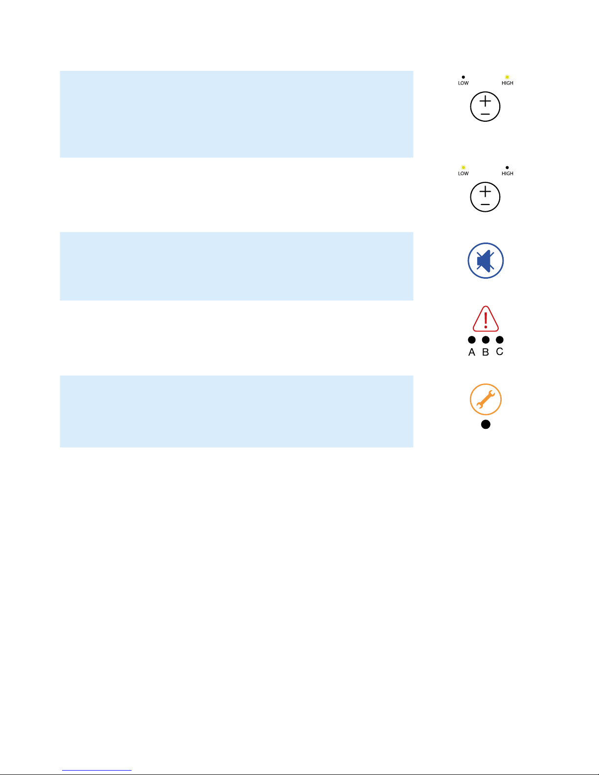
This symbol when illuminated (the green indicator light) is used to indicate that the equipment is
on or ready for use.
When a patient requires more pressure in the cells, as they may be uncomfortable or feel as
though the support surface is too soft or unstable, then please select a “High” setting (pressure
26mmHg). This must only be used by a trained clinician as often too high pressures can further
agitate certain patient conditions.
When a patient requires less pressure in the cells, as they may be uncomfortable or indeed hyper
sensitive to cell movement or if the patient is still reddening further, then please select a “Low”
setting (pressure 18mmHg). This must only be used by a trained clinician.
This function is used to silence the Audible Warning. The LED will remain lit if the Audible
Warning has been silenced previously, however a fault is still detected. Refer to the power switch
in order to re-set fully. If the Audible Warning continues to sound repeatedly, along with an
illuminated light, then an engineer must be called.
This symbol indicates an “Audible Warning Failure”.
Please see troubleshooting guide below for how to re-set.
This symbol when illuminated indicates a Service is required.
DHG recommends a service every 8760 hours of operation (one continuous year running).
LED Mode Settings
Note: Please ensure (when available) that all securing straps on the base of the mattress are secured onto
the MOVING PARTS of the bed frame.
For shut down procedure, see 4.2 Control Unit section.
Power On / Off
Dynamic /Firmer Setting
Silence Audible Warning
Audible Warning Failure
Service Indicator
Low / Comfort Pressure Setting
DIRECTHEALTHCAREGROUP.COM
6
MERCURY ADVANCE SMARTCARE
Warning / Fault Cause
Control Unit does
not operate;
no display lights
illuminate
The Control
Unit may not be
attached to a
power source or
a fuse may need
replacing.
1. Check the Control Unit is connected to mains power outlet with the correct voltage.
2. Check the Control Unit is switched on. Switch off and unplug the unit before restarting.
3. Check the mains plug fuse (5 AMP) then check both Control Unit fuses (1 AMP) –
fuses can be released using a screwdriver to push and turn.
Do not try to open the Control Unit. Opening the unit could cause personal injury
or equipment damage.
Ensure the replacement of fuses is carried out accordance with local legislation.
Warning LED C
+ Audible Warning
Mains failure /
Other
See above,
plus:
1. Check the Control Unit is connected to mains power outlet with the correct voltage.
2. Check the Control Unit is switched on. Switch off and unplug the unit before restarting.
3. Check the mains plug fuse (5 AMP) then check both Control Unit fuses (1 AMP) – fuses can be
released using a screwdriver to push and turn.
Do not try to open the Control Unit. Opening the unit could cause personal injury or equipment
damage.
Ensure the replacement of fuses is carried out accordance with local legislation.
Warning LED B
+ Audible Warning
Pressure too low 1. Reset the warning – turn off power and press the Audible Warning mute button.
2. Check that the Dual Function Connector is firmly attached the Control Unit (located on the left
of the Control Unit case). Check all air hoses along the inside of the mattress – each should be
firmly connected. Check each air cells is securely attached to its connecting pipe.
3. Check all cells, pipes and hoses for any air leakage.
4. Check that the air filter cover is correctly secured and the air filter is clean.
5. Switch on power.
Warning LED B+C
+ Audible Warning
Pressure too low /
Air pipe kinked
1. Check the blue external umbilical air pipe that is between the mattress and the Dual Function
Connector is not kinked, twisted or damaged and that the CPR Tag is firmly secured.
2. Check all air hoses along the inside of the mattress – each should be firmly connected.
3. Check each air cell is securely attached to its connecting air pipe.
Warning LED A
+ Audible Warning
Pressure
too high
1. Reset the warning – turn off power and press the Audible Warning button.
2. Disconnect the air hoses to reduce pressure, reconnect when pressure has decreased.
3. Check for twists in the air hoses between Mattress and Control Unit.
Warning LED A+B
+ Audible Warning
Alternating
Mode Failure (no
alternation)
1. Reset the warning – turn off Power and press the Audible Warning mute button.
2. Disconnect the air hoses to reduce pressure – reconnect when pressure has decreased.
Warning LED A,B+C
+ Audible Warning
Initialising Failure 1. Press the Audible Warning mute button to silence the Audible Warning.
2. Check all air hoses along the inside of the mattress – each should be firmly connected.
Check each air cell is securely attached to its connecting air pipe.
3. Check that the Dual Function Connector is firmly attached the Control Unit (located on the left
of the Control Unit casing).
Solution
3. Troubleshooting

DIRECTHEALTHCAREGROUP.COM
SERVICE MANUAL
7
4. Installation
4.1 Mattress (This is the applied part type BF)
Place the Mercury Advance SMARTcare Mattress directly on to the bed platform ensuring that
the blue multi-stretch waterproof cover is on top and that the umbilical hose is located at the left-
hand corner at the foot end of the bed. Note: The umbilical hose can be located inside the cover
under the “Open Here for Air Inlet” printed in the bottom left hand corner of the mattress.
Cover the Mattress with a loose-fitting sheet.
Static Mattress Use
The Mercury Advance SMARTcare can be used as a pressure reducing mattress for patients at
High Risk of pressure ulcer damage without the need to attach the Control Unit. In this mode, the
Mercury Advance SMARTcare mattress will continuously offload pressures in vulnerable areas
such as the heels.
Alternating Mattress Use
If / When required, the Mercury Advance SMARTcare Mattress can be used as an alternating
mattress system by attaching the Dyna-Form Mercury Advance Control Unit.
No other system should be attached to the mattress as the design settings and internal air
pressure properties of the Dyna-Form Mercury Advance Control Unit are specific to this
mattress only.
The Mercury Advance SMARTcare is a replacement mattress system and should NOT be
placed on top of any existing mattress.
The start-up time from static to dynamic mode is immediate.
4.2 Control Unit
Hang the Control Unit onto the footboard. The mounting hooks swivel to suit the thickness of
the footboard or rail. Connect the umbilical hose to the Control Unit, place the supplied 3-pin
electrical plug into the wall outlet and switch on:
(a) Open the zip located at the bottom left hand side of the mattress and pull out the blue umbilical hose.
(b) Attach the blue umbilical hose to the Control Unit by connecting the Dual Function Connector
at the end of the umbilical hose to the air inlet connector at the bottom left hand side of the
Control Unit.
(c) Re-close the zip as far as possible without clamping the blue umbilical hose to ensure the
mattress and air cells are sealed within the cover.
(d) Shut down is the reverse of items a, b & c above.
5. Operation
Attach the supplied mains cable to the Control Unit by inserting the “kettle” type connector into the recess
located on the left-hand side of the Control Unit. The mains cable has been designed specifically as a
removable part to aid in easy replacement should it become damaged in use.
Power cables not supplied by Direct Healthcare Group are not recommended for use with this Control Unit.
The mains plug should be turned off and removed from wall socket as a means of isolation.
Plug the mains cable into a suitable 230v mains socket and switch on the Control Unit using the on/off
switch.
After the Control Unit has been turned on both the “High “and the “Low” lights will flash together
intermittently until the Control Unit has attained its initial operating pressure. Once the Control Unit has
attained its initial operating pressure the “Low” light will stay on constantly and the mattress is ready for use.

DIRECTHEALTHCAREGROUP.COM
8
MERCURY ADVANCE SMARTCARE
5.1 Low / High Settings
The Mercury Advance SMARTcare Mattress, in Alternating Mode, has two pressure settings. The
initial setting that the control unit will revert to upon set up is “Low”. The “Low” comfort setting is ideal for
the lighter patient or those who feel discomfort when on a normal alternating air type mattresses system.
However, for patients with existing pressure damage or those at Very High Risk, it is recommended that
dependant on the clinical judgement of the clinician, the “High” setting is activated by pressing the +/-
button once, which is located on top of the Control Unit.
In “High” Mode the Control Unit attains more of the characteristics of an alternating air mattress system
whilst still utilising the advantages of the static foam inserts. Repeatedly pressing the ‘mode’ button
enables the Low & High modes to be selected in turn.
5.2 Static Hybrid Mode
Should a patient show signs of no longer needing dynamic therapy and depending on clinical judgement, the
Mercury Advance SMARTcare System can be stepped down to a ‘foam in air’ static hybrid mattress.
To do this, turn off the Mercury Advance Mark II Control Unit and disconnect the Dual Function Connector
by pressing the red pump release button.
5.3 CPR Deflation
The CPR system consists of a manually operated tag located on the blue umbilical attached to the Control Unit.
Pulling the red CPR Tag will deflate the mattress air system back to that of a static foam mattress.
Warning: Removal of the Dual Function Connector alone will not expel air as quickly as the CPR Tag.
Do not rely on the Dual Function Connector for CPR, always use the CPR Tag to expel air from the mattress quickly.
Note: After a short period as the Mattress deflates the ‘Low Pressure’ Audible Warning is activated and
can be cancelled by switching the Control Unit off.
5.4 Troubleshooting
For assistance (if needed) in setting up, using or maintaining the Mercury Advance SMARTcare
system, or to report unexpected operation or events, please contact Direct Healthcare Group on the
contact details on the reverse of this manual.
6. Transportation
To change the location of the mattress, press the pump release button on the Dual Function Connector
and allow the mattress to return to its Static Mattress form. Switch off the Control Unit using the on/off
switch and disconnect the electrical supply cable from the mains socket.
The mattress can now be moved to a new location where it must immediately be reconnected to the
mains electrical supply and the Control Unit switched back on. Once the Mattress has been refilled, the
‘Alternating’ mode will automatically revert back to the Low setting and should be reselected to High
should this be desired by the clinician.
Warning: The Mattress will not ‘alternate’ when disconnected from Control Unit and /or the mains electrical.
Also, refer to environmental conditions section at rear of this manual.
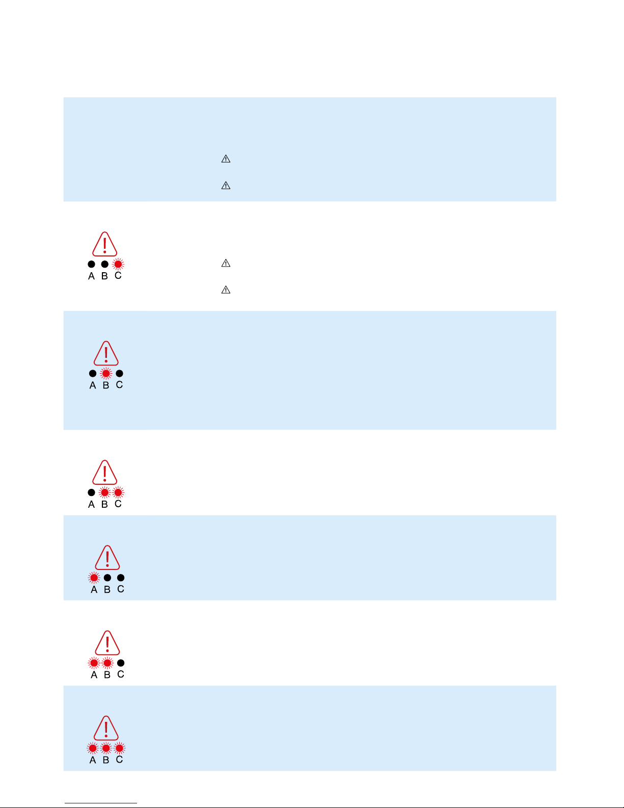
7. Warnings
Warning conditions are indicated by a flashing red display accompanied by an Audible Warning.
In each case the user should respond by turning the Control Unit’s switch off and investigating the cause.
7.1 High Pressure Warning
This condition could be caused, for example by a kinked umbilical hose or visitors, and others,
sitting suddenly on the Mattress.
7.2 Low Pressure Warning
This condition could be caused, for example, by incorrect fitting of the Dual Function Connector,
opening of the CPR Tag or a leak in the Mattress due to a cut or puncture.

DIRECTHEALTHCAREGROUP.COM
SERVICE MANUAL
9
8. Maintenance Procedures
8.1 Safety Warning
Only qualified technicians trained or formally approved by Direct
Healthcare Group Ltd. in the operation and maintenance of
Direct Healthcare Group products may carry out maintenance,
modification or repair work on the equipment. Unqualified
personnel attempting to work on Direct Healthcare Group Control
Units risk serious injury to themselves and others and possibly
death by electrocution. Inlet fuse NOT to be replaced by operator
or patient, to be replaced by service personnel only.
Warning – Do not modify this equipment without
authorisation of Direct Healthcare Group.
8.1.1 Servicing
Direct Healthcare Group recommend that the control unit be
serviced annually from installation. The service light will illuminate
after 8760 hours of operation (one year of continuous operation).
The unit contains no user serviceable parts and should only be
carried out by persons as described in section 8.1. DHG will make
available on request all manuals, component parts lists and other
information necessary for any suitably qualified person (As in 8.1)
to carry out repair or service the system. For Service, maintenance
and any questions regarding this please contact DHG.
8.2 Audit
Caution: It is recommended that an audit of all mattresses within
a ward/department is carried out at least annually.
In the community setting, an audit should also be considered
between each change of patient.
Please refer to the document Medical Device Alert: All types of
bed mattresses (MDA/2010/002), and also the BHTA guidance
on the care, cleaning and inspection of healthcare mattresses
(BHTA Protect, Rinse and Dry). Details on how to audit your
mattress are available from Direct Healthcare Group.
8.3 Cleaning Procedures
Warning: Before cleaning the System make sure that the Control
Unit is disconnected from the mains electricity supply.
Do not immerse the Control Unit in water or other fluids.
Do not autoclave, nor use phenol for cleaning.
Do wash hands before commencing the cleaning process.
Wear appropriate protective clothing such as gloves, apron
and a mask.
Ensure all work surfaces are cleaned before and after contact
with the Mattress.
8.4 Warning – Cleaning the Mattress
1. Cleaning should take place after use or between patients.
2. With cover left on the Mattress disconnect the Mattress from
the Control Unit.
3. Clean the surface of the wash down table with a Sodium
Hypochlorite solution or an equivalent disinfectant.
4. Wash the Mattress top using hot water (60 degrees C)
containing detergent – dry with a paper towel.
5. Use a Sodium Hypochlorite solution diluted to 1,000 parts
per million available chlorine. For heavy contamination use
a Sodium Hypochlorite solution diluted to 10,000 parts per
million available chlorine.
Please ensure thorough rinsing after
cleaning.
6. Using suitable brush, hot water, detergent or Sodium
Hypochlorite solution, clean the umbilical hose, CPR Tag and
Dual Function Connector. Dry with paper towel.
7. If required, the Mattress Cover may be removed and
machine-washed at a temperature of 80 degrees C, for not
less than 10 minutes. The individual Air Cells can be wiped
down with established disinfectants.
7.5 Initialising Failure
This will be indicated by a warning LED on A, B and C and an Audible Warning after circa 45mins.
1. Press the Audible Warning mute button to silence the Audible Warning.
2. Check the power cable is firmly plugged into the mains outlet and the Control Unit;
and check the mains power is switched on.
3. Check the Control Unit fuse (1 AMP) – fuses can be released using a screwdriver
to push and turn.
7.3 Mains Failure Warning
This condition may be caused, for example if Mains power is lost.
7.4 Alternating Mode Failure (no alternation)
This will be indicated by a warning LED on A and B and an Audible Warning.
1. Reset the warning – turn off Power and press the Audible Warning mute button.
2. Disconnect the air hoses to reduce pressure – reconnect when pressure has decreased.
DIRECTHEALTHCAREGROUP.COM
10
MERCURY ADVANCE SMARTCARE
1
2
3
4
5
6
7
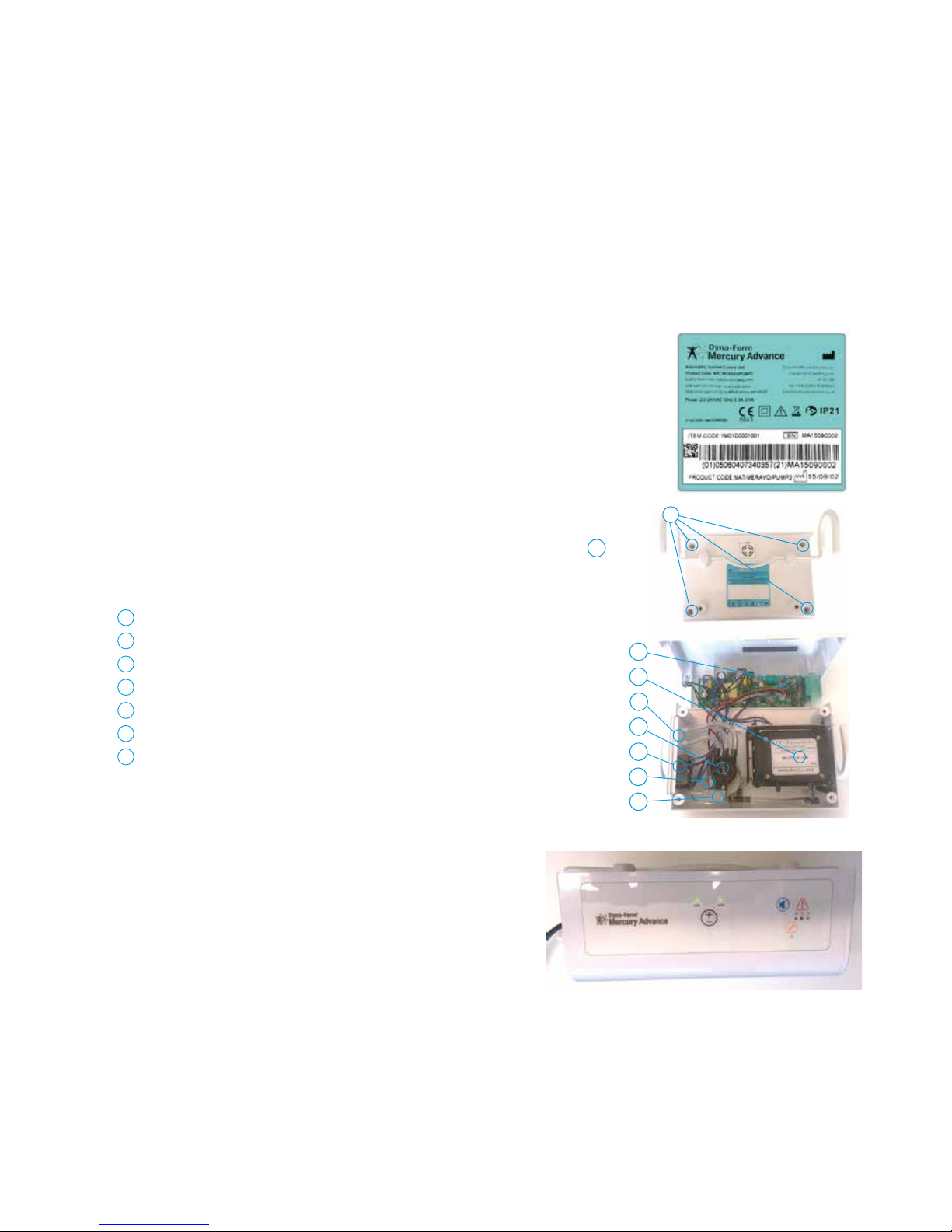
8.7 Opening the Control Unit.
To remove the front of the enclosure,first unscrew the four corner screws ( Marked A ).
8.8 System Layout
8.9 Checking the System
1. Plug in the mattress to the Control Unit.
2. Plug in the mains cable to the IEC inlet and switch on the power.
3. The LED indication LOW and HIGH pressure will flash during start up.
4. The Control Unit will run until the mattress is inflated to the pre-
set pressure setting (LOW).
5. The LED indicating the setting (LOW) will be lit.
6. The system is ready to use.
7. The system is designed so the Control Unit sets the pressure
as required and will run for short periods of time to maintain the
required pressure or alter it when moving from LOW to HIGH.
Control PCBA
Compressor
Air Outlets
Rotor valve
IEC Power Inlet
Rotor valve motor
Micro switch
1
2
3
4
5
6
7
8.6 Serial Number Identification.
The Control Unit is identified by serial number and GS1 compliant barcoding using
both 128 and 2D bar code identifiers.
Both product code and manufacture date are shown on the identification label.
The above Control Unit serial number is MA15090002 and manufacture date is 02
day of 09 month of year 2015.
A
8. To avoid shrinkage of the cover, line dry in an indoor clean environment or tumble dry on a
low heat setting not exceeding 40 degrees C and not for longer than 10 minutes. Covers
must be thoroughly dried before re-fitting to the mattress.
8.5 Warning – Cleaning the Control Unit
The Control Unit can be cleaned by wiping with a cloth dampened with a detergent
solution or a Sodium Hypochlorite solution. Also, refer to symbol chart.
8.5.1 Warning
Ensure the Mercury Advance Smartcare System is not exposed to:
1. Excessive heat sources e.g. fires, radiators etc.
2. Water, particularly immersion of the Control Unit.
DIRECTHEALTHCAREGROUP.COM
SERVICE MANUAL
11
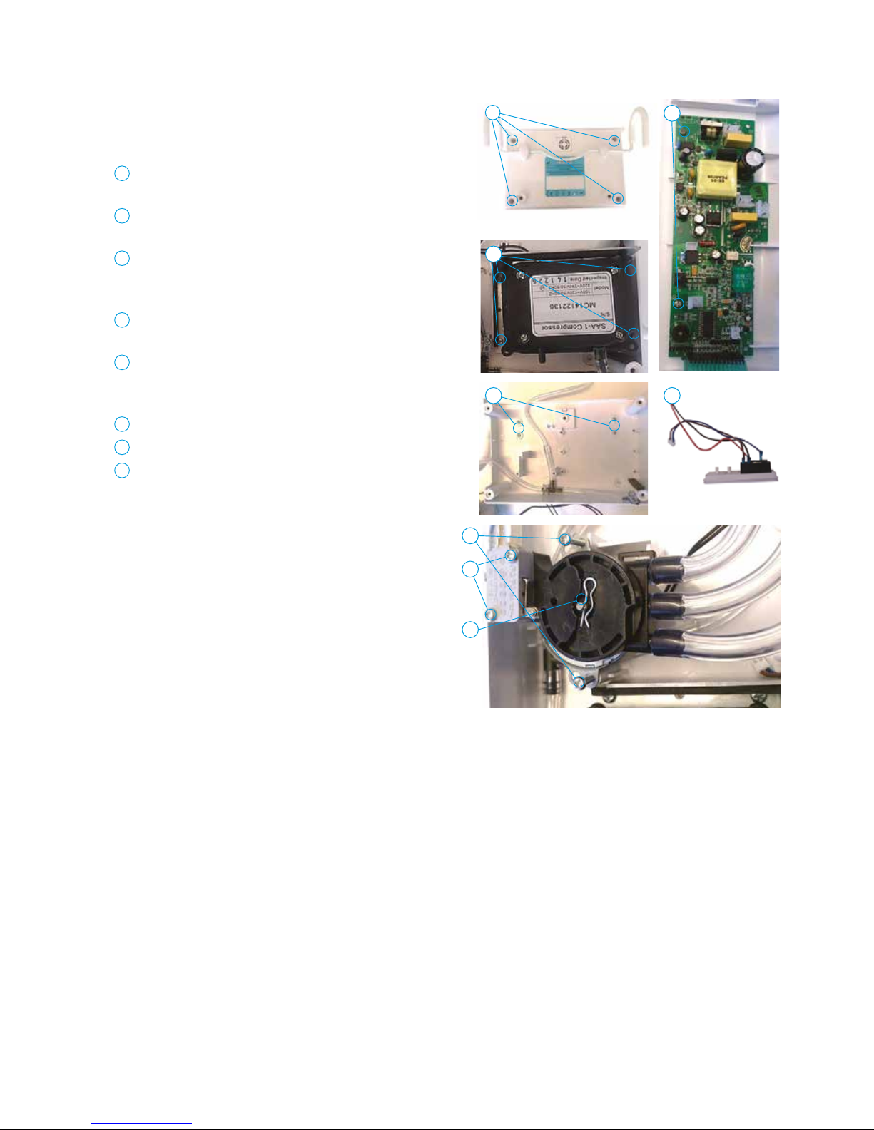
8.10 Taking the System Apart
The Control Unit is designed so almost all components
can be removed without disassembling other parts.
1 Open the housing by removing the 4 screws from
the bottom part.
2 Remove PCBA by disconnecting the cables and unscrewing
the 2 screws.
3 Remove the compressor by unscrewing the 4 screws
and disconnect the power cable from the PCBA and the
air tube on the compressor.
4 Remove the air out/power in part by disconnecting the air
tubes and the cables from the PCBA.
5 Remove the rotor valve by pulling out the locking pin
from the motor axes and removing the air tubes from
the rotor valve.
6 Remove the rotor valve motor by unscrewing the 2 screws.
7 Remove the micro switch by unscrewing the 2 screws.
8 Removing the hooks requires the compressors to be removed
first. Remove the four screws on the inside of the back part
of the housing and then release the attachment part for the
hooks from the outside of the housing.
8.11 Reassembling the System
To reasemble the Control Unit, reverse the steps in 8.10 ensuring
that the pressure sensor tubing runs underneath the compressor
during reassembly.
1 2
3
4 8
5
6
7
DIRECTHEALTHCAREGROUP.COM
12
MERCURY ADVANCE SMARTCARE
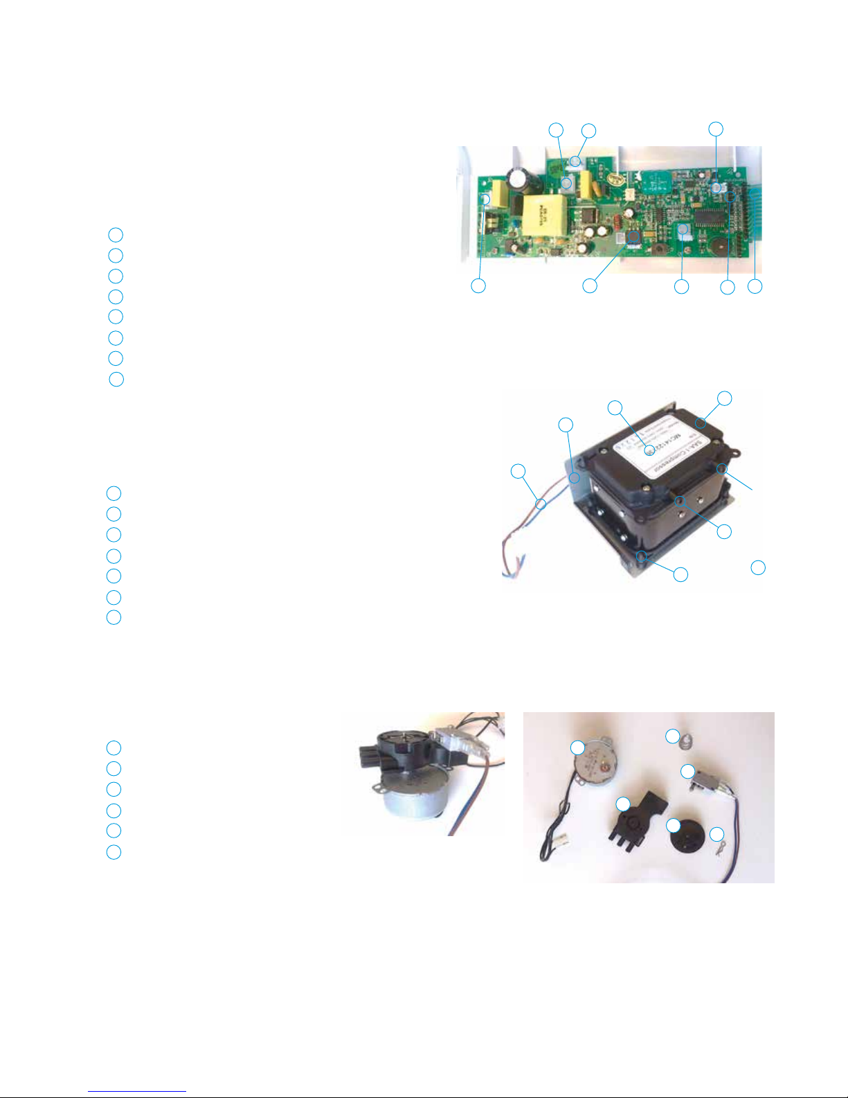
8.11 The components
The main components in the Mercury Advance Control Unit.
8.11.1 PCBA
8.11.2 The compressor
8.11.3 Rotor valve with motor
Connector for Compressor
Connector for Rotor valve motor
Connector for Micro switch (Brown/blue)
Connector for Membrane
Connector for Software download (for manufacturer only)
Connector for (red/black) from Power input
Pressure sensor
Connector for Power in (brown/blue)
1
1
2
2
3
4
4
5
5
6
6
7
7 8
8
Attachment plate
Label
Silencer
Air outlet
Air inlet
Rubber suspension
Compressor power
cable (Brown/blue)
Rotor valve motor
Spring
Micro switch
Lock pin
Rotor valve cap
Rotor valve body
1
1
2
2
2
3
3
3
4
4
4
5
5 5
6
6
6
7
1
2
3
4
5
6
7
1
3
DIRECTHEALTHCAREGROUP.COM
SERVICE MANUAL
13
1 2 3
1
2
3
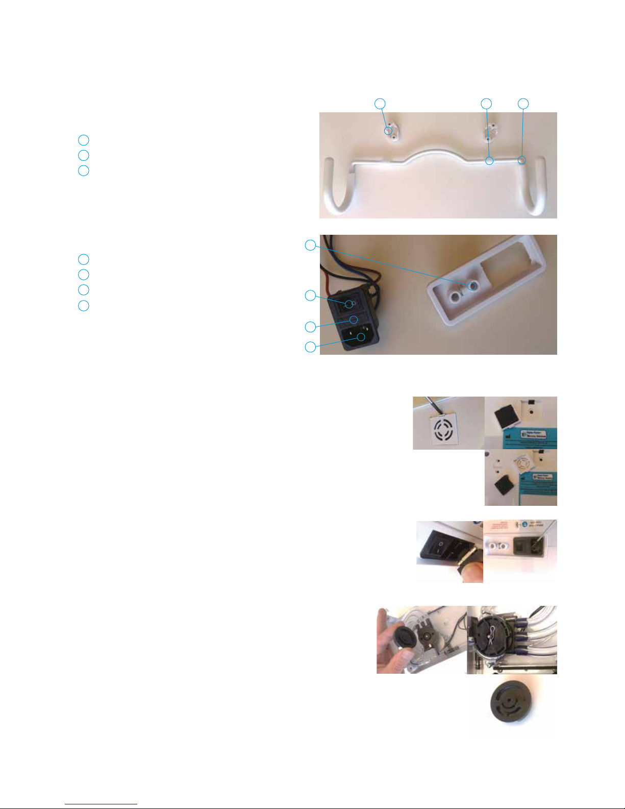
8.11.4 The hooks
Hook attachment
Rubber suspension
Hook
1
2
3
8.110.5 Air inlet/power outlet
Air outlet
Power inlet
Fuse holder
ON/OFF
1
2
3
4
4
8.12 Filter Maintenance
The Control Unit has a light that when illuminated indicates a Service is required.
8.13 Fuse
1. Change the air filter: Remove air filter holder by pressing the
plastic catch downwards and lifting the air filter holder up.
Take out the filter and put in a new one and put the filter
holder back.
2. Check the fuse: Check the fuse and if required add a spare in
the holder for the fuse in the fuse holder.
8.14 Rotor Valve Maintenance
The Control Unit has a light that when illuminated indicates a
Service is required. Open the housing by remove the 4 screws from
the bottom part.
3. Grease the rotor valve: Press down the cap of the rotor valve
release the lock pin. Lift of the cap and put a thin layer of grease
(Silicone grease dow Corning Molykote PG21, 613000103) on
the bottom side of the cap. Assemble back again.

DIRECTHEALTHCAREGROUP.COM
14
MERCURY ADVANCE SMARTCARE
9. Technical Specification
Guidance and manufacturer’s declaration – electromagnetic emission
The MAT1610001 is intended for use in the electromagnetic environment specified below.
The customer or the user of the system should ensure that it is used in such an environment.
Emission test Compliance Electromagnetic environment – guidance
RF emissions
CISPR 11
Group 1 The system uses RF energy only for its internal function.
Therefore, its RF emissions are very low and are not likely
to cause any interference in nearby electronic equipment.
RF emission
CISPR 11
Class B The system is suitable for use in all establishments, including
domestic establishments and those directly connected to
the public low-voltage power supply network that supplies
buildings used for domestic purposes.
Harmonic emissions
IEC 61000-3-2
Class A
Voltage fluctuations/flicker
emissions
IEC 61000-3-3
Complies
Declaration – electromagnetic emissions - for all ME EQUIPMENT and ME SYSTEMS
8.5 Warning – Cleaning the Control Unit
The Control Unit can be cleaned by wiping with a cloth dampened with a detergent solution or a Sodium Hypochlorite solution.
Also, refer to symbol chart.
8.5.1 Warning
Ensure the Mercury Advance
SMARTcare
System is not exposed to:
1. Excessive heat sources e.g. fires, radiators etc.
2. Water, particularly immersion of the Control Unit.

DIRECTHEALTHCAREGROUP.COM
SERVICE MANUAL
15
9. Technical Specification
Declaration – electromagnetic immunity
Guidance and manufacturer’s declaration – electromagnetic immunity
The MAT1610001 is intended for use in the electromagnetic environment specified below.
The customer or the user of the system should ensure that it is used in such an environment.
Immunity test IEC 60601
test level
Compliance level Electromagnetic
environment – guidance
Electrostatic discharge (ESD)
IEC 61000-4-2
±6 kV contact
±8 kV air
±6 kV contact
±8 kV air
Floors should be wood,
concrete or ceramic tile.
If floor are covered with
synthetic material, the relative
humidity should be at least
30%.
Electrical fast transient/burst
IEC 61000-4-4
±2 kV for power
supply lines
±1 kV for input/output line(s)
±2 kV for power
supply lines
±1 kV for input/output line(s)
Mains power quality
should be that of a typical
commercial or hospital
environment.
Surge Immunity Test
IEC 61000-4-5
± 1 kV line(s) to line(s) ±1 kV differential mode Mains power quality
should be that of a typical
commercial or hospital
environment.
Voltage dips, short
interruptions and voltage
variations on power supply
input lines
IEC 61000-4-11
Voltage Dips
%U T
Period
(Cycles)
Voltage Dips
%U T
Period
(Cycles)
Mains power quality
should be that of a typical
commercial or hospital
environment. If the user of
the Span system requires
continued operation during
power mains interruptions,
it is recommended that the
system be powered from an
uninterruptible power supply
or a battery.
30 25 30 25
60 5 60 5
>95 0.5 >95 0.5
Voltage
Interruption
% U T
Seconds Voltage
Interruption
% U T
Seconds
>95 5 >95 5
Power frequency (50Hz)
magnetic field
IEC 61000-4-8
3 A/m 3 A/m Power frequency magnetic
fields should be at levels
characteristic of a typical
location in a typical
commercial or hospital
environment.
NOTE U T is the a.c. mains voltage prior to application of the test level.

DIRECTHEALTHCAREGROUP.COM
16
MERCURY ADVANCE SMARTCARE
9. Technical Specification
Guidance and manufacturer’s declaration – electromagnetic immunity
The MAT1610001 is intended for use in the electromagnetic environment specified below.
The customer or the user of the system should ensure that it is used in such an environment.
Immunity test IEC 60601 test level Compliance level Electromagnetic environment – guidance
Conducted RF
IEC 61000- 4-6
Radiated RF
IEC 61000-4-3
3 Vrms
150 kHz to 80 MHz
3 V/m (Professional
Healthcare Environment)
10 V/m (Home
Healthcare Environment)
80 MHz at 2.7 GHz
3 Vrms
10 V/m
Portable and mobile RF communications equipment
should be used no closer to any part of the CT515,
including cables, than the recommended separation
distance calculated from the equation applicable to the
frequency of the transmitter
Recommended separation distance
d = 1.167√P
d = 1.167√P 80 MHz to 800 MHz
d = 2.333√P 800 MHz to 2.5 GHz
Where P is the maximum output power rating of the
transmitter in watts (W) according to the transmitter
manufacturer and d is the recommended separation
distance in meters (m).
Field strengths from fixed RF transmitters, as
determined by an electromagnetic site survey,
a
should
be less than the compliance level in each frequency
range.
b
Interference may occur in the vicinity of equipment
marked with the following symbol:
NOTE 1 At 80 MHz and 800 MHz, the higher frequency range applies.
NOTE 2 These guidelines may not apply in all situations. Electromagnetic propagation is affected by absorption and reflection
from structures, objects and people.
a. Field strengths from fixed transmitters, such as base stations for radio (cellular/cordless) telephones and land mobile radios,
amateur radio, AM and FM radio broadcast and TV broadcast cannot be predicted theoretically with accuracy. To assess the
electromagnetic environment due to fixed RF transmitters, an electromagnetic site survey should be considered. If the measured
field strength in the location in which the Span system is used exceeds the applicable RF compliance level above, the system should
be observed to verify normal operation. If abnormal performance is observed, additional measures may be necessary, such as
reorienting or relocating the system.
b. Over the frequency range 150kHz to 80MHz, field strengths should be less than 3V/m.
Declaration – electromagnetic immunity – for ME EQUIPMENT and ME SYSTEMS that are not LIFE-SUPPORTING

DIRECTHEALTHCAREGROUP.COM
SERVICE MANUAL
17
9. Technical Specification
Recommended separation distances between portable and mobile RF communications equipment and the MAT1610001
Alternating Control Unit
The MAT1610001 is intended for use in an electromagnetic environment in which radiated RF disturbances are controlled.
The customer or the user of the system can help prevent electromagnetic interference by maintaining a minimum distance between
portable and mobile RF communications equipment (transmitters) and the system as recommended below, according to the maximum
output power of the communications equipment.
Rated maximum output
power of transmitter (W)
Separation distance according to frequency of transmitter (m)
150 KHz to 80 MHz
d = 1.167√P
80 MHz to 800 MHz
d = 1.167√P
800 MHz to 2.5 GHz
d = 2.333
√
P
0.01 0.117 0.117 0.233
0 .1 0.369 0.369 0.738
11.16 7 1.16 7 2.333
10 3.689 3.689 7.379
100 11.667 11.667 23.333
For transmitters rated at a maximum output power not listed above, the recommended separation distance d in meters (m) can be
estimated using the equation applicable to the frequency of the transmitter, where P is the maximum output power rating of the
transmitter in watts (W) according to the transmitter manufacturer.
NOTE 1 At 80 MHz and 800 MHz, the separation distance for the higher frequency range applies.
NOTE 2 These guidelines may not apply in all situations. Electromagnetic propagation is affected by absorption and reflection
from structures, objects and people.
Recommended separation distances between portable and mobile RF communications equipment and the EQUIPMENT
or SYSTEM – for ME EQUIPMENT or ME SYSTEM that are not LIFE – SUPPORTING
DIRECTHEALTHCAREGROUP.COM
18
MERCURY ADVANCE SMARTCARE
10. Technical Data
10.1 Control Unit
Serial Number ................... As per label on rear of Control Unit
Electrical Supply. .............................. 220 – 240 volts, 50 Hz
Power Consumption ...............................................10 watts
Fuses ................................................................TA1H 250V
Protection against shock ...........................................Class 2
Noise Level ...............................................Approx. 30 dB (A)
Dimensions ...........................................245 x 160 x 95 mm
Weight...................................................................... 1.7 kg
Service Interval ............................... 12 months / 8760 hours
Expected life ............................................................5 years
Shelf life of parts ......................................................5 years
10.2 Mattress
Serial Number .....................Label on inside of mattress cover
Number of Air Cells ................ 15 Air Cells / 1 Static Foam Cell
Dimensions ......................... 1980 x 880 x 150mm (Nominal)
Weight.....................................................................13.4kg
Expected life of Mattress ...........................................5 years
Shelf life of Mattress parts .........................................5 years
11. Optimum Conditions
(Applies to Mattress and Control Unit)
11.1 Environment Conditions for Use
Transport .................................................... -25˚C – +70˚C
Storage ...................................................... -25˚C – +70˚C
Usage ......................................................... +5˚C – +40˚C
Humidity .......................................................... 10% – 93%
Atmospheric Pressure ........................... 700hPa – 1060hPa
Operational Altitude .............................................. ≤ 2000m
11.2 Exposure
Exposure to direct sunlight, dust, lint and general debris is not
considered to be an issue with the Mercury Advance System.
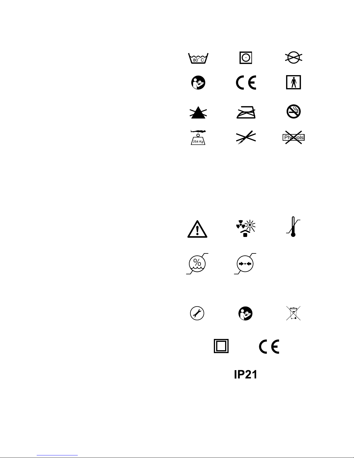
REFER TO
USER MANUAL
SERVICE
REQUIRED
TUMBLE DRY ON LOW
0843
DO NOT IRON
DO NOT USE
SHARP INSTRUMENTS
WASH AT 80˚
REFER TO
USER MANUAL
DO NOT BLEACH
MAXIMUM USER
WEIGHT LIMIT
254 KG / 40 ST
ONES
DOUBLE INSULATED
CLASS II
NO SMOKING
DO NOT USE
PHENOL
DO NOT DRY CLEAN
TYPE BF
APPLIED PART
DO NOT DISPOSE OF
WITH HOUSEHOLD WASTE.
PLEASE REFER TO DHS WEBSITE
THIS IS A STAT EMENT THAT
ALERTS THE USER TO THE
POSSIBILITY OF SERIOUS INJURY
OR OTHERWISE ADVERSE
REACTIONS WITH THE USE
OR MISUSE OF THE DEVICE
WARNING
THIS IS A STAT EMENT THAT
ALERTS THE USER TO THE
POSSIBILITY OF A PROBLEM
WITH THE SYSTEM ASSOCIATED
WITH ITS USE OR MISUSE
CAUTION
CAUTION
HUMIDITY
LIMITATION
ATMOSPHERIC PRESSURE
LIMITATION
PROTECT FROM HEAT
AND RADIOACTIVE SOURCES
TEMPERATURE
LIMITATION
0843
IP: INGRESS PROTECTION
2: PROTECTION AGAINST FINGERS OR
OTHER OBJECT NOT GREATER THAN
80MM IN LENGTH AND 12MM IN DIAMETER
1: PROTECTION FROM VERTICALLY
DRIPPING WATER
Mattress Symbols
12. Symbols Guide
General Symbols
REFER TO
USER MANUAL
SERVICE
REQUIRED
TUMBLE DRY ON LOW
0843
DO NOT IRON
DO NOT USE
SHARP INSTRUMENTS
WASH AT 80˚
REFER TO
USER MANUAL
DO NOT BLEACH
MAXIMUM USER
WEIGHT LIMIT
254 KG / 40 STONES
DOUBLE INSULATED
CLASS II
NO SMOKING
DO NOT USE
PHENOL
DO NOT DRY CLEAN
TYPE BF
APPLIED PART
DO NOT DISPOSE OF
WITH HOUSEHOLD WASTE.
PLEASE REFER TO DHS WEBSITE
THIS IS A STAT EMENT THAT
ALERTS THE USER TO THE
POSSIBILITY OF SERIOUS INJURY
OR OTHERWISE ADVERSE
REACTIONS WITH THE USE
OR MISUSE OF THE DEVICE
WARNING
THIS IS A STAT EMENT THAT
ALERTS THE USER TO THE
POSSIBILITY OF A PROBLEM
WITH THE SYSTEM ASSOCIATED
WITH ITS USE OR MISUSE
CAUTION
CAUTION
HUMIDITY
LIMITATION
ATMOSPHERIC PRESSURE
LIMITATION
PROTECT FROM HEAT
AND RADIOACTIVE SOURCES
TEMPERATURE
LIMITATION
0843
IP: INGRESS PROTECTION
2: PROTECTION AGAINST FINGERS OR
OTHER OBJECT NOT GREATER THAN
80MM IN LENGTH AND 12MM IN DIAMETER
1: PROTECTION FROM VERTICALLY
DRIPPING WATER
Control Unit Symbols
REFER TO
USER MANUAL
SERVICE
REQUIRED
TUMBLE DRY ON LOW
0843
DO NOT IRON
DO NOT USE
SHARP INSTRUMENTS
WASH AT 80˚
REFER TO
USER MANUAL
DO NOT BLEACH
MAXIMUM USER
WEIGHT LIMIT
254 KG / 40 STONES
DOUBLE INSULATED
CLASS II
NO SMOKING
DO NOT USE
PHENOL
DO NOT DRY CLEAN
TYPE BF
APPLIED PART
DO NOT DISPOSE OF
WITH HOUSEHOLD WASTE.
PLEASE REFER TO
DHS WEBSITE
THIS IS A STAT EMENT THAT
ALERTS THE USER TO THE
POSSIBILITY OF SERIOUS INJURY
OR OTHERWISE ADVERSE
REACTIONS WITH THE USE
OR MISUSE OF THE DEVICE
WARNING
THIS IS A STAT EMENT THAT
ALERTS THE USER TO THE
POSSIBILITY OF A PROBLEM
WITH THE SYSTEM ASSOCIATED
WITH ITS USE OR MISUSE
CAUTION
CAUTION
HUMIDITY
LIMITATION
ATMOSPHERIC PRESSURE
LIMITATION
PROTECT FROM HEAT
AND RADIOACTIVE SOURCES
TEMPERATURE
LIMITATION
0843
IP: INGRESS PROTECTION
2: PROTECTION AGAINST FINGERS OR
OTHER OBJECT NOT GREATER THAN
80MM IN LENGTH AND 12MM IN DIAMETER
1: PROTECTION FROM VERTICALLY
DRIPPING WATER

DIRECTHEALTHCAREGROUP.COM
SERVICE MANUAL
19
Contraindications For Use (Warning)
The Mercury Advance SMARTcare System should not be used for
patients with unstable fractures, gross oedema, burns,
or intolerance to motion.
General Information (Caution) (Warning)
• There are no special skills required to operate the system.
• The Medical Professional is responsible for applying his/her
best medical judgment when using the system.
• The electricity supply is of the type indicated on the Control
Unit.
• Check the mains lead is free from damage and is positioned
so as not to cause an obstruction, or injury. E.g. Strangulation
of a child or trip hazard.
• Ensure the mains lead cannot become trapped or crushed,
e.g. by raising or lowering of the bed or bed rails or any other
moving object.
• The Control Unit must only be used with a suitably approved
power cord and plug set as supplied by DHG.
• The system is not to be used in the presence of flammable
anaesthetics.
• Suitable for continuous use.
• Not suitable for sterilisation.
• Do not position the Control Unit to make it difficult to disconnect
the power supply or plug.
• Do not place the System on or close to a source of heat.
• Do not use with hot water bottles or electric blankets.
• DHG strongly advise against smoking whilst the Control Unit is
in use. This is to prevent accidental secondary ignition of items
which may be flammable e.g. bed linen. The materials used in
the manufacture of the Mercury Advance System comply with
the required fire safety regulations.
• Do not use sharp objects on or near the mattress system
as this will cause damage.
• Do not store in damp conditions.
• Do not use in an oxygen enriched environment.
• Not suitable for use in an Outdoor Environment.
• Intended for both Home Healthcare and Professional Healthcare
environments.
• Do not connect to any other medical device or equipment.
• Correct fuse rating MUST be used. Failure to do so could result
in the risk of a fire.
• The System should be cleaned after use or between patients.
Refer to Cleaning section.
• All internal and external hoses must be free of twists, kinks.
The external hose should also be properly connected and
positioned so that the risk of obstruction or injury is eliminated.
• Do not use bleach, phenols. Chlorine based products which
exceed 1000ppm. Solvents or alcohol based cleaners.
• All the above warnings and cautions together with safety
considerations should be observed at ALL times during its use.
• Select correct setting ‘High’ or ‘Low’ as required. Care should
be taken not to accidentally change settings once set. This may
affect the desired requirement of the therapy. This could also be
caused by pets, pests or children.
• This device does not emit radiation.
13. Detachable/Removable Parts
1. Mattress (Detached from the Control Unit by disconnecting
the Dual Function Connector). Part No. MAT1610003
(or variants of for the size)
2. Electric power cable. (Removed from the Control Unit by
pulling the cable away from the mains inlet on the side of the
Control Unit).
Part No. SP021016
N.B. The battery is an integral part of the PCB and is not
removable or changeable.
Caution
Use of detachable parts not listed is not recommended by
Direct Healthcare Group.
14. Disposal
Please refer to DHG website for recommendations and
responsibilities for disposal within the UK WEEE guidelines.
C22760
DIRECTHEALTHCAREGROUP.COM
Intelligent Pressure Care
Specialist Seating
Rental & Service Solutions
I
S
O
1
3
4
8
5
A
2
8
3
2
2
LIT-00024 Issue 2
Date: February 2018
Direct Healthcare Group
Withey Court, Western Industrial Estate
Caerphilly, United Kingdom
CF83 1BF
T: +44 (0) 845 459 9831
F: +44 (0) 845 459 9832
Asia Pacific
Direct Healthcare Group PTY Ltd.
PO Box 562, Wembley
Western Australia 6913
T: +61 (0) 423 852 810
Table of contents
Other Direct Healthcare Services Medical Equipment manuals


