manuals.online logo
Brands
  1. Home
  2. •
  3. Brands
  4. •
  5. Breas
  6. •
  7. Medical Equipment
  8. •
  9. Breas Vivo 45 LS User manual

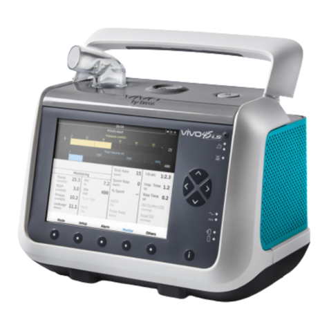
Breas Vivo 45 LS User manual

Vivo 45 LS
Quick Reference Guide for Healthcare Professionals
Rear View
Equipment Designation
Exhalation valve port
Connection for low
pressure/bleed-in
oxygen
Item/ Symbol Description Color
CO2interface port
SpO2interface port
Remote start/stop and audio pause
port
Remote alarm, nurse call interface port
Mains/ External DC inlet
This is not a complete guide for the Vivo 45 LS. See your manual for complete instructions.
Setting Up and Powering on the Ventilator
• All users must be trained in the use of the Vivo 45 LS prior to operating
the device.
• Before operating the ventilator, inspect the ventilator, power supply,
power cord and accessories for any signs of damage. Do not use the
device or accessories if damage is suspected.
• Do not use the ventilator while positioned in a warm place, such as in
direct sunlight or close to a radiator as this may lead to a temperature
outside of specications.
Placing the Ventilator Before Use
Place the Vivo 45 LS on a solid at surface. It should be placed lower than
the patient. Make sure that nothing can block the patient air inlet. Make
sure that nothing can block the cooling air inlet or outlet.
Connecting the Vivo 45 LS to Mains (AC Power Outlet)
1. Plug the power supply into the power
inlet.
2. Make sure a clicking sound is heard to
ensure the power supply is completely
inserted.
3. Connect the power supply’s power cord to
the mains supply.
Connecting Accessories
Connecting and Disconnecting the
Accessory Cables
1. Insert the cable in the appropriate port.
(See Rear View)
2. Make sure to insert the connector with
the marking pointing upwards.
3. Pull the connector sleeve, not the cable itself or the cable strain relief to
release the connector.
EtCO2sensor
SpO2Connection
interface
SpO2 nger clip sensor Click-in battery
1
Click-in Battery
The click-in battery is intended as a power source during transportation, or
if the primary AC power source fails.
Installing the Click-in Battery
1. Lift Handle and press button 1 to release
the side cover.
2. Open and remove the side panel.
3. Insert the click-in battery. Make sure
the latch at the bottom of the click-in
compartment is engaged.
4. Close the side panel. Make sure there is a
clicking sound to secure the side panel.
When removing the battery, press down
the latch at the bottom of the battery
compartment and tilt the ventilator
sideways.
1
PtcCO2sensor
Customer Support Line: 855-436-8724
Monday through Friday 8am to 5pm EST
009018
Revision D-1
Connecting the Patient Circuit
1. Inspect the circuit for damage.
2. Connect the patient circuit to the patient
air outlet on the ventilator.
3. If using an active exhalation valve patient
circuit, connect the exhalation valve
connector to the back of the ventilator.
Caution: Make sure the leakage port of the circuit is not blocked or
obstructed. This port prevents rebreathing by ushing the exhaled air.
Performing the Pre-use Test
Always perform a pre-use test when connecting a new patient circuit.
1. If the Pre-use test prompt screen appears,
select Yes.
If you do not see the prompt, go to the
“Others” menu and select “Pre-use
Test>>”
2 The rst step of the Pre-use Test will
determine the circuit being used. Ensure
circuit is connected and Press “OK”. Verify
correct circuit is detected and Press “Yes”.
3. The Pre-use Test will now check the circuit
resistance. Remove the leakage port from
the circuit and ensure nothing is blocking
the end of the circuit. Press “OK”
4. The next step is the circuit compliance test.
Block the end of the patient circuit with
your hand and press “OK”
5. The Pre-use Test result will be displayed.
Press “OK” if pre-use test was completed
successfully. Otherwise repeat the Pre-use
Test.
Setting Ventilator Parameters
Navigating the menu buttons
• Press the Mode button to open the Mode
menu.
• Use the Up and Down arrows to move
between Ventilation, Breath, Patient and
Device modes.
• Use the left and right arrows select
parameters within the selected mode.
• Use Next button to move to the Settings menu. Pressing Next a second
time moves to the Alarms menu.
• Within the Settings menus, the Up and Down arrows move between
parameters. The Left and Right arrows change the value of the selected
parameter (A “high” alarm can be turned OFF by continuing to press the
Right arrow to the end of the range. A “low” alarm can be turned OFF
using the Left arrow).
• Press the Conrm button when all settings have been entered.
• The Setup and Alarms buttons can be used to modify settings/alarms at
any time. A second press of the Setup or Alarms button displays a menu
of Secondary settings/alarms.
Switching from Home Mode to Clinical Mode
1. Press and hold the left and right buttons
simultaneously.
2. Release when the progress bar is lled.
Starting Treatment
1. Press the Start/Stop button.
2. Press the menu button indicating “Start”.
Handling Alarms
Audible Signal Pause and Reactivation
The audible signal can be paused for 60 seconds by pressing the Audio
Pause button.
The audible signal can be reactivated by
pressing the Audio Pause button again.
If a new alarm condition occurs during the
audio pause period, the audible signal will
be reactivated.
Audible alarm level
Range/Performance: 1 to 5, where 1 is the lowest volume setting and 5 is
the highest volume setting.
• Set the alarm sound level so that alarms can be clearly heard at a distance.
leakage port interface
pilot pressure
tube
2
Leak circuit
MPV circuit Active exhalation valve circuit
Mode
Arrow buttons
Customer Support Line: 855-436-8724
Monday through Friday 8am to 5pm EST
009018
Revision D-1
How to set audible alarm level
• Use the Navigation buttons to enter the “Others” menu
• Use the down button to enter the “Device Settings” menu
• Use the down button to select “Alarm Sound Level”
• Use left and right arrows to change alarm sound level to desired setting
Monitoring
Power Source Indicators
The Source of the Power currently being used is indicated on the right side
of the front panel. (See Front View). The lit LED next to the icons means the
following power source is in use:
Click battery
Internal battery
Battery Status Symbols
State of charge (alternates with battery symbol)
Stopping Treatment
1. To stop treatment and enter standby mode, rst press and hold the Start/
Stop button on the top.
2. Release the Start/Stop button when the progress bar is lled.
3. Press “OK” or the Audio Pause Button
to stop the treatment.
Mouthpiece Ventilation (MPV)
• Mouthpiece ventilation is intended for adult patients who are able to
initiate breaths with the mouthpiece circuit.
• MPV Mode shall be used with a mouthpiece
interface only.
• Using MPV Mode will result in deactivation of some
alarms and features normally active in other modes.
• When the back up rate is set to zero, the Apnea
alarm can be used to detect that the patient is not
triggering any breaths. For example, when the
apnea alarm is set to 45 seconds, the alarm will
sound when the patient has not triggered a breath
in the last 45 seconds.
• The low pressure alarm can be used to detect the
situation in which the patient cannot reach the
mouthpiece (when the backup rate is set greater
than 0). Set the low pressure alarm setting above the
peak pressure that occurs when the mouthpiece is
open. When the mouthpiece is open, the alarm will
trigger on the next backup breath.
• When leaving MPV Mode, check the alarm settings and that the actual
circuit connected matches the Patient Circuit Type setting.
Using the ventilator with a Nurse Call System
The purpose of the nurse call system interface is to forward alarms from the
Vivo 45LS to the hospital’s nurse call system.
The hospital’s nurse call system will remain active as long as any alarm
remains active on the Vivo 45 LS.
Connecting the ventilator to a Nurse Call System
1. Connect the nurse call cable at the back of
the ventilator and to the hospital’s nurse call
system.
2. The nurse call system interface must be
tested before use. Test the connection by
triggering an alarm on the ventilator and
verify that the nurse call system activates
before use.
Testing the Nurse Call System Interface:
1. Trigger a Disconnection Alarm on the
ventilator.
2. Verify the hospital’s nurse call system activates and remains active.
3. Trigger a High MV Alarm on the ventilator (with the Disconnection Alarm
still active).
4. Verify the nurse call system remains active (with no interruption).
5. Resolve both alarms on the ventilator.
6. Verify that the hospital’s nurse call system deactivates.
Using the Ventilator with the Remote Alarm
When installing a remote alarm system, check
that it operates as intended before starting
the treatment. The LED on the remote alarm
is (Green) when the remote alarm unit is on.
Before starting treatment, make sure this LED
is on.
Supervising a Patient During Treatment:
• When a patient is treated there must be
a supervising person present during the
treatment.
• The supervising person needs to take care
of alarms and conditions that the patient
cannot solve on their own.
• Always have immediate access to an
alternative means of ventilation which is ready for use.
• Failure to have an alternative means of ventilation can result in serious
injury or patient death if the ventilator fails.
Installing and Calibrating the FiO2Sensor:
• See section 5.8.3.1 of the clinician’s manual for instructions on installing
the FiO2sensor.
• See section 5.8.3.2 of the clinician’s manual for instructions on calibrating
the FiO2sensor.
3
MPV patient circuit
Mouthpiece
Peak pressure
Vte
FiO2(%)
Customer Support Line: 855-436-8724
Monday through Friday 8am to 5pm EST
009018
Revision D-1
Transporting the Ventilator
Protective Cover
1. Open protective cover using zippers.
2. Place ventilator into protective cover so
that the screen is facing up.
3. Close protective cover and zip to secure
ventilator.
Mount and dismount the Vivo 45 LS as shown in the picture
Cleaning and Maintenance
• Refer to section 7.2 of the Clinician’s manual for instructions on cleaning
and replacing patient air lters.
• Refer to section 7.2 of the Clinician’s manual for instructions on cleaning
and replacing cooling air lter.
16 Esquire Rd, N. Billerica, MA 01862 USA
Phone 855-436-8724
www.breas.us
*Vivo by Breas, Breas and the Breas logo are trademarks of Breas Medical AB. © 2020 Breas Medical – All rights reserved. Breas Medical reserves the right to make changes in specifications and features shown herein, or discontinue the product described at any
time without notice or obligation. Contact your Breas representative for the most current information. MAR-007716-v.0
4
4
Customer Support Line: 855-436-8724
Monday through Friday 8am to 5pm EST
009018
Revision D-1

Other manuals for Vivo 45 LS

2

Other Breas Medical Equipment manuals

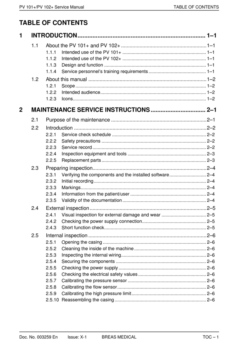
Breas PV 102+ User manual

Breas

Breas PV 102+ User manual

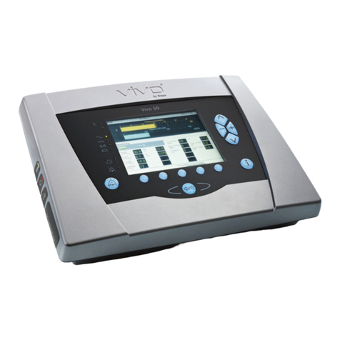
Breas Vivo 50 User manual

Breas

Breas Vivo 50 User manual

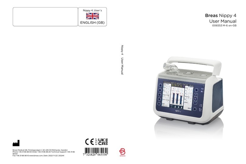
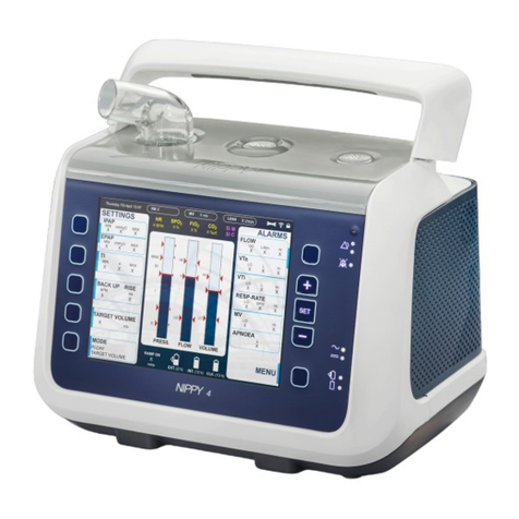
Breas Nippy 4 Series User manual

Breas

Breas Nippy 4 Series User manual

Breas Vivo 65 User manual

Breas

Breas Vivo 65 User manual

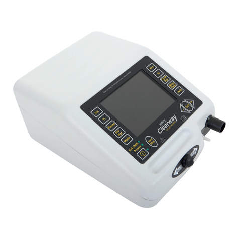
Breas NIPPY Clearway User manual

Breas

Breas NIPPY Clearway User manual

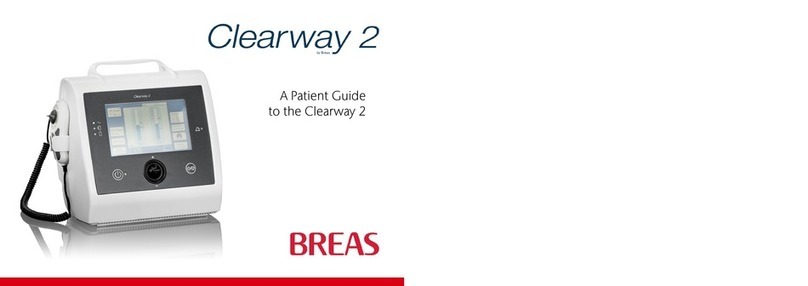
Breas Clearway 2 User manual

Breas

Breas Clearway 2 User manual

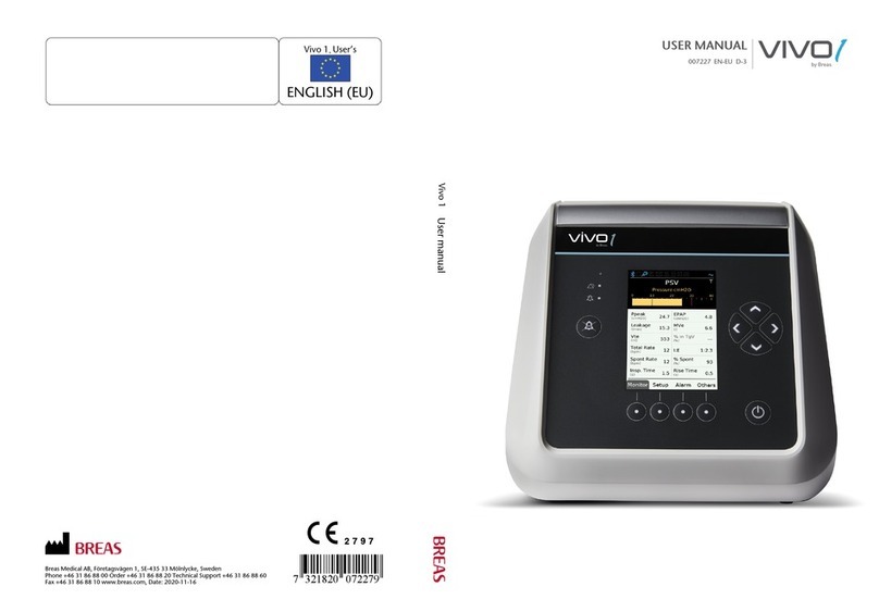
Breas Vivo 1 User manual
Breas

Breas Vivo 1 User manual

Breas NIPPY User manual

Breas

Breas NIPPY User manual

Breas iSleep 20+ User manual

Breas

Breas iSleep 20+ User manual

Breas Vivo 50 User manual

Breas

Breas Vivo 50 User manual

Breas Vivo 3 User manual

Breas

Breas Vivo 3 User manual

Breas Clearway 2 User manual

Breas

Breas Clearway 2 User manual

Breas Vivo 45 LS User manual

Breas

Breas Vivo 45 LS User manual

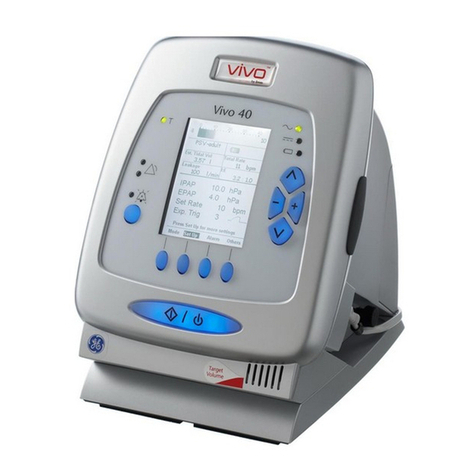
Breas Vivo 40 User manual

Breas

Breas Vivo 40 User manual

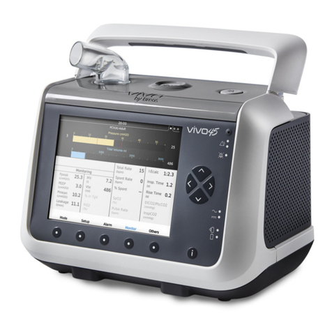
Breas Vivo 45 User manual

Breas

Breas Vivo 45 User manual

Breas NIPPY ST+ User manual

Breas

Breas NIPPY ST+ User manual

Breas Vivo 45 LS User manual

Breas

Breas Vivo 45 LS User manual

Breas Z1 User manual

Breas

Breas Z1 User manual

Breas iSleep20+ User manual

Breas

Breas iSleep20+ User manual

Breas Vivo 3 User manual

Breas

Breas Vivo 3 User manual

Breas Vivo 45 User manual

Breas

Breas Vivo 45 User manual

Breas NIPPY Clearway User manual

Breas

Breas NIPPY Clearway User manual

Breas Clearway 2 User manual

Breas

Breas Clearway 2 User manual

Breas Vivo30 User manual

Breas

Breas Vivo30 User manual

Popular Medical Equipment manuals by other brands

Otto Bock E-MAG Active 17B203 Instructions for use

Otto Bock

Otto Bock E-MAG Active 17B203 Instructions for use

Integra LifeSciences MAYFIELD Infinity XR2 A2079 instruction manual

Integra LifeSciences

Integra LifeSciences MAYFIELD Infinity XR2 A2079 instruction manual

promotal 73 user guide

promotal

promotal 73 user guide

Otto Bock 50K14 Genu Arexa PCL Instructions for use

Otto Bock

Otto Bock 50K14 Genu Arexa PCL Instructions for use

Posture Pump Disc Hydrator instructions

Posture Pump

Posture Pump Disc Hydrator instructions

Invacare HomeFill HF2PCM2KIT Operator's manual

Invacare

Invacare HomeFill HF2PCM2KIT Operator's manual

Joerns Oxford 0Y0050 User instruction manual

Joerns

Joerns Oxford 0Y0050 User instruction manual

Protac MyFit Directions for use

Protac

Protac MyFit Directions for use

Whitehall SP-1600-A Operation and maintenance manual

Whitehall

Whitehall SP-1600-A Operation and maintenance manual

Saneo 4SPORT instruction manual

Saneo

Saneo 4SPORT instruction manual

Vermeiren D100 instruction manual

Vermeiren

Vermeiren D100 instruction manual

Flaem AeroFlaem P0703EM F400 Instructions for use manual

Flaem

Flaem AeroFlaem P0703EM F400 Instructions for use manual

Accutome a-scan plus user guide

Accutome

Accutome a-scan plus user guide

iCoolsport IcePro instruction manual

iCoolsport

iCoolsport IcePro instruction manual

Zimmer SonoOne Instructions for use

Zimmer

Zimmer SonoOne Instructions for use

KCI ActiV.A.C. user manual

KCI

KCI ActiV.A.C. user manual

toWell SKP1000 user manual

toWell

toWell SKP1000 user manual

Otto Bock 1B1-2 Meridium Instructions for use

Otto Bock

Otto Bock 1B1-2 Meridium Instructions for use

manuals.online logo
manuals.online logoBrands
  • About & Mission
  • Contact us
  • Privacy Policy
  • Terms and Conditions

Copyright 2025 Manuals.Online. All Rights Reserved.