10(41)
User manual in Original
Doc. ref: User manual 500A-GTS-E65 Rev. F
Mälarvägen 9, SE-141 71 Segeltorp, Sweden Fax: +46 8 724 6070 Web page: www.disperator.se
3. Product Description and Technical Specification
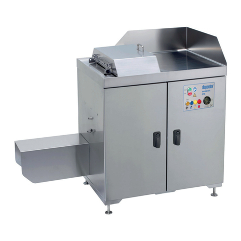
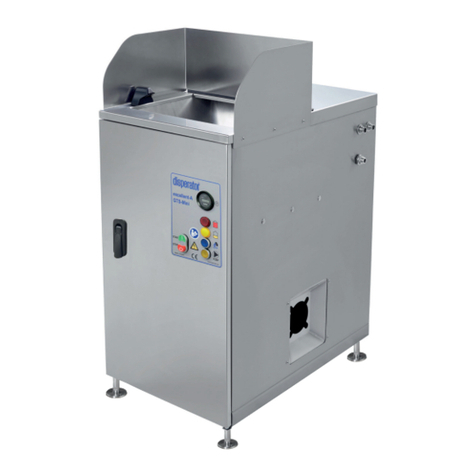
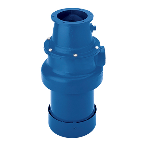
3.1.Food Waste Processor 500A-GTS-E65 EXCELLENT-Series for Free-standing
Installation
Immediately and efficiently removing the heaviest part of kitchen waste –i.e. food leftovers - is a
necessity in any commercial kitchen. In the event water-based food waste disposers connected to the
municipal sewer system is not permitted in your community, a by Disperator developed unique and
patent pending technology can handle the task for you. When using a GTS-Series processor, food
waste can hygienically and without any heavy lifting or manual transfer easily take care of and reduce
the total amount of refuse –by volume, but above all by weight!
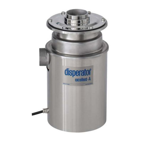
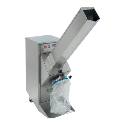
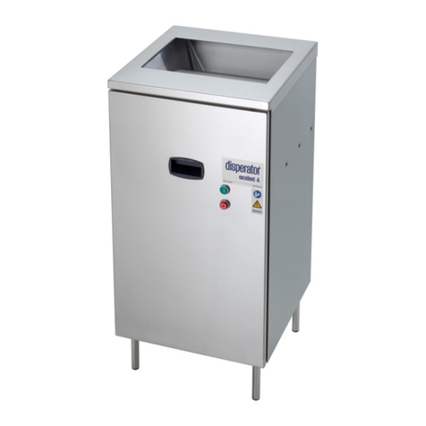
Regardless of the selected model, the disposal procedure is the same. Food waste is fed down the
inlet hopper of the machine and ground into small particles in a disposer for further transport in a pipe
using a processor pump to a sealed and odorless tank. The tank is emptied by a vacuum truck
approximately every four weeks or according to the driving schedule that applies in your municipality.
Depending upon preference, the tank may be placed outdoors buried in the ground, as well as placed
indoors. One of the unique benefits of this processor technology is that the pumping of the ground
food waste can be done with minimal amount of flushing water, which gives a good operating
economy as the tank does not need to be emptied as often. The slurry is transported to an anaerobic
digestion facility and converted into valuable renewable energy resource (i.e. biogas), and often the
digested residue can also be used as fertilizer on farmland. Biogas is one of our society’s most
environmentally clean and desired energy forms, as fuel for cars as well as for the production of heat
and electricity.
In its standard version the GTS-processor has a capacity of up to 15 l/min. With an average amount of
food waste of 0.15 l/served meal, the processor is able to take care of food waste generated by as
many as 4,000 served guests/hour. And this despite the fact that the storage tank, if required, can be
located over 100 meters away.
To suit existing interior and logistics within the kitchen, the processor outlet may be positioned either
to the left or to the right of infeed opening, thus giving full flexibility in planning your kitchen and
possibility to fully utilize valuable space. Disperator's broad assortment of different technical solutions
for source separation of food waste can be adapted to your specific kitchen and your specific working
environment, regardless of size or layout, and regardless of the specific municipal’s food waste
handling rules in your community!
Food waste disposers within the Disperator Excellent Series have the Declaration of Compliance issued
by DNV, verifying compliance with applicable sections of MARPOL consolidated edition 2011/2012
ANNEX V for disposal of ground food waste into the open sea.

