Distech Controls Allure UNITOUCH Manual
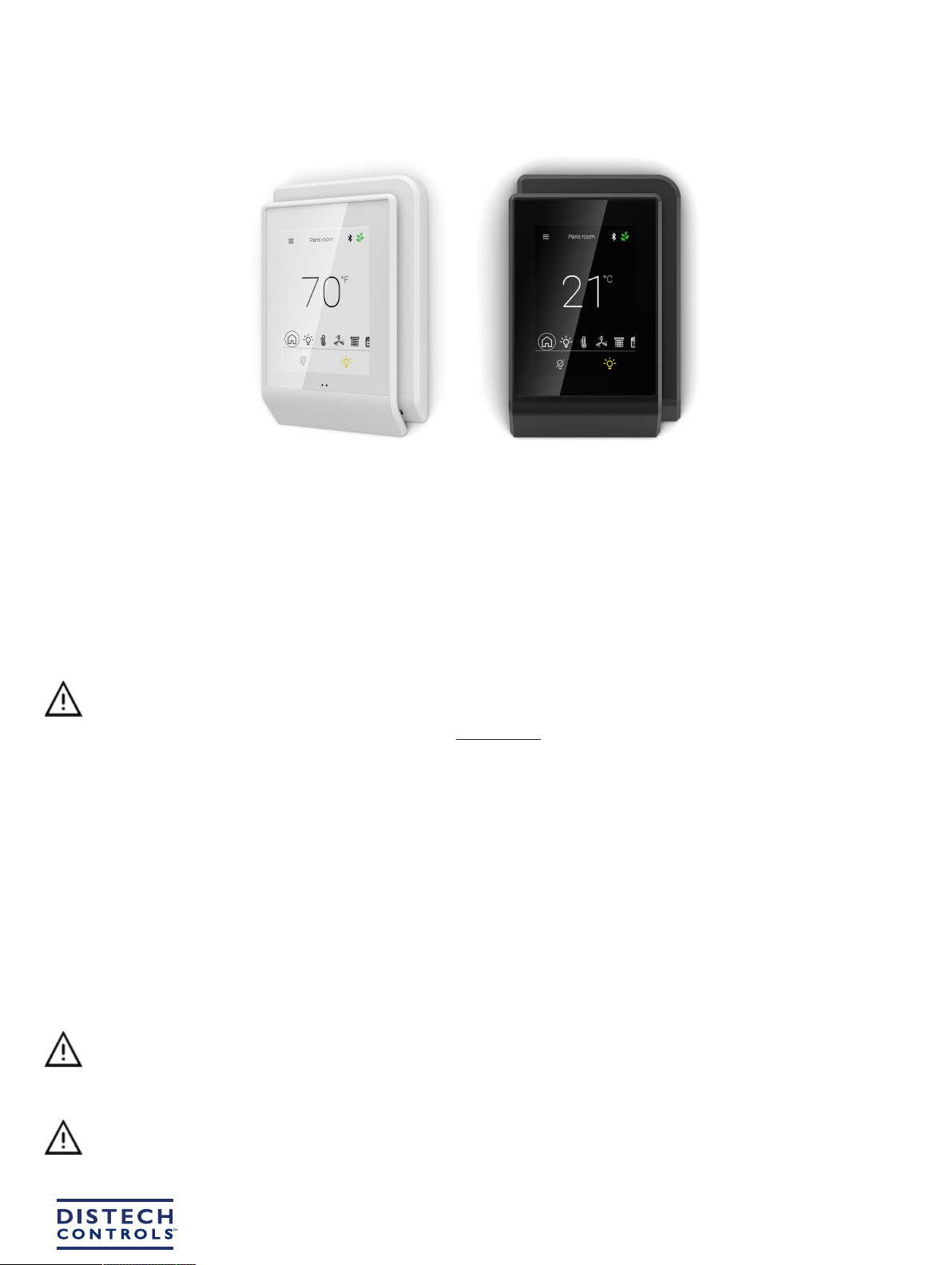
Allure UNITOUCH™
Product Description
The Allure UNITOUCH is an elegant and occupant focused room device that provides an intuitive user interface, allowing wireless control of room com-
fort parameters from a smartphone using
Bluetooth
® low energy technology. Its compact style and slim profile provides a modern appearance when in-
stalled in any setting.
The high resolution 3.5” capacitive touchscreen makes this communicating sensor the ideal all-in-one solution for a wide range of HVAC, lighting, and
sunblind application; a perfect addition to the Smart Room Control solution.
General Wiring Recommendations
Risk of Electric Shock: Turn off power before any kind of servicing to avoid electric shock.
£Comply with all network and power supply guidelines outlined in the Network Guide.
£Use the screws, wall anchors, and wire nuts included for wall mounting and wiring.
£All wiring must comply with electrical wiring diagrams as well as national and local electrical codes.
£We recommend using Cat5e cable to connect the Allure UNITOUCH to the controller.
£For an easier installation, a flat style Cat5e cable with a low profile connector is recommended. See Distech Controls Field Device product offerings
for more information.
General Installation Requirements
For proper installation and subsequent operation of the device, pay special attention to the following recommendations:
£Allow for proper clearance around the device’s enclosure and wiring terminals to provide easy access for hardware configuration and maintenance.
£Orient the device with the ventilation slots towards the top to permit proper heat dissipation.
£The device is designed to operate under the following environmental conditions:
– Operating temperature from
– Storage temperature from
– Relative humidity from 0% to 90%, non-condensing.
Any type of modification to any Distech Controls product will void the product’s warranty
£Upon unpacking, inspect the contents of the carton for shipping damages. Do not install a damaged device.
£Ensure proper ventilation of the device and avoid areas where corroding, deteriorating or explosive vapors, fumes or gases may be present.
Make wiring connections to the device last. Pulling the cable while it is connected can damage the connector.
Installation Guide
2 / 7
Take reasonable precautions to prevent electrostatic discharge to the device when installing, servicing or during operation. Discharge
accumulated static electricity by touching one’s hand to a well-grounded object before working with the device.
Device Markings
Certain markings (symbols) can be found on the side of the product and are defined as follows:
Symbol Description
CE marking: the device conforms to the requirements of applicable EC directives.
UKCA marking: the device conforms to the requirements of applicable Great Britain regulations.
UL marking: conforms to the requirements of the UL certification.
FCC marking: This device complies with FCC rules part 15, subpart B, class B.
Warning Symbol: Significant information required. Refer to the Hardware Installation Guide.
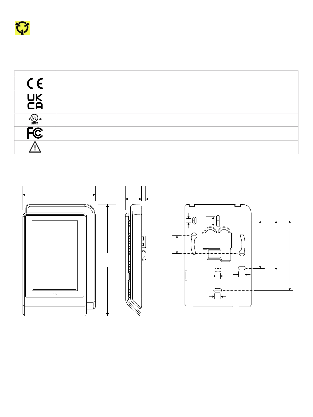
Device Information
5
[0.2]
131.5
[5.18]
85.5
[3.37]
19
[0.75]
mm
[Inches]
58
[2.28]
82
[3.23]
10
[0.40]
56
[2.20]
5
[0.20]
5 [0.20] 7 [0.28]
7 [0.28]
21
[0.83]
Front View of Back
Mounting Plate
Figure1: UNITOUCH Dimensions

3 / 7
Faceplate
release tab
Faceplate
release tab
Security screw
Figure2: UNITOUCH Security Screw and Faceplate Tab Locations
EOL
OFF
EOL
ON
NLIGHT
SUBNET
24Vdc only
Front Cover Rear View
Protocol Switch
Pass-Though Subnetwork RJ-45
Connectors
Not currently
supported
Subnetwork End of Line
Disabled Enabled
Down
Position
Subnet
Enabled
Up
Position
nLight
Enabled
not currently
supported
( ) factory default
position
( )
Figure3: UNITOUCH Jumper and Dip Switch Locations

4 / 7
Mounting Instructions
The Allure UNITOUCH has been specially designed for easy installation. However, certain conditions apply when choosing a suitable location for the de-
vice:
£Install the device in a location of average temperature and approximately 1.5 m (5 ft) above the floor
£The device should be installed approximately 15cm (6”) from a corner to provide sufficient access to the faceplate release tabs.
£The device should not be installed on an exterior wall.
£The device should not be installed near a heat source.
£The device should not be installed near an air discharge grill.
£The device should not be installed in a place where it can be affected by the sun.
£Install the device in an area that provides proper device ventilation. Nothing must restrain air circulation to the device.
The Allure UNITOUCH has not been designed for outdoor use.
Mounting hardware with a separate sub-base is provided with the device for installation on drywall or on an electrical junction box.
Electrical Junction Box Installation Procedure
The Allure UNITOUCH sensor can be mounted in most American, European or Asian style electrical junction box using screws.
1. Remove the front cover of the device:
– Remove the security screw
– Using an appropriately sized tool, press in the two (2) release tabs on the sides of the device and pull the front cover out from the bottom. See
Figure 2 [pg.3] for security screw and release tab locations.
2. Pull all cables 15cm (6”) out of the wall and insert them through the central hole of the back plate.
3. Ensure the EOL jumpers are correctly set and that the protocol toggle is in the SUBNET (default) position. See Figure 3 [pg.3] for jumper and dip
switch component locations.
4. Make sure that the mounting surface is flat and clean.
5. Screw the back plate onto the electrical junction box.
6. Plug the wire(s) into the connector(s). Gently push excess wiring back into the wall.
7. Reattach the front plate and make sure it clips tightly into place. Tighten the security screw.
Wall Mounting Installation Procedure
Figure4: UNITOUCH backplate screw positions
The Allure UNITOUCH can be mounted on drywall using the supplied screws.
1. Remove the front cover of the device:
– Remove the security screw
– Using an appropriately sized tool, press in the two (2) release tabs on the sides of the device and pull the front cover out from the bottom. See
Figure 2 [pg.3] for security screw and release tab locations.
2. Pull all cables 15cm (6”) out of the wall and insert them through the central hole of the back plate.
3. Ensure the EOL jumpers are correctly set and that the protocol toggle is in the SUBNET (default) position. See Figure 3 [pg.3] for jumper and dip
switch component locations.
4. Align the back plate with the wall and mark the location of the mounting holes on the wall. Make sure to orient the proper end of the back plate facing
upwards.

5 / 7
5. Remove the back plate and drill holes in the wall if necessary.
6. Install anchors in the wall if necessary.
7. Make sure that the mounting surface is flat and clean.
8. Screw the back plate onto the wall. Do not over tighten.
9. Plug the wire(s) into the connector(s). Gently push excess wiring back into the wall.
10.Reattach the front plate and make sure it clips tightly into place. Tighten the security screw.
About an Allure UNITOUCH Equipped with a CO₂ Sensor
The Allure UNITOUCH equipped with a CO2 sensor are factory calibrated to accurately read CO2 concentration levels.
Under normal conditions, an Allure UNITOUCH equipped with CO2 sensor will typically reach its operational accuracy
after 25 hours of continuous operation on the condition that it was exposed to ambient air reference levels of 400
ppm ±10 ppm CO2.
Bluetooth Connection Modes
The Allure UNITOUCH supports several Bluetooth communication modes. Please refer to the Xpress
Network
Utility or ECLYPSE user guide for more
details on how to change this mode.
Mode Description
Commissioning Bluetooth connection is used for commissioning the device. This option is the factory default mode (default PIN code
999995) and has short range for commissioning purposes only.
Disabled Bluetooth connection is disabled and does not allow any wireless connections to the device.
Open Bluetooth connection is open and is not authenticated with a PIN code. We recommend this option for rooms or areas that
are accessible to anyone.
Private Bluetooth connection is authenticated with a six (6) digit PIN code. When this mode is selected, you will be prompted to
change the PIN code as the default PIN code is not allowed while using Private mode. We recommend this option for private
rooms and areas.
Subnet Information and Communications Wiring
The Allure UNITOUCH is only compatible with ECLYPSE Series controllers, namely the ECY-TU/PTU, ECY-VAV, ECY-303, and ECY-CSC. Subnet ca-
ble length is limited to 100m (328ft) between the controller and the last device on the subnet for all Bluetooth low energy devices. This maximum subnet
length must be respected to ensure the proper functioning of all devices.
If the UNITOUCH is the last device on the subnetwork, its EOL termination must be set to ON. All other subnetwork devices must have their EOL termi-
nations set to OFF.
The ECLYPSE User Guide provides extensive information and requirements to implement this subnetwork. It contains information about network length,
cable type, addressing, etc. It can be downloaded from the Distech Controls website.
If you make your own patch cable, use Category 5e cable crimped with RJ-45 connectors either as T568A or T568B.
Do not crimp one connector as T568A and crimp the other connector as T568B on the same cable.
PIN 1 Not used (but linked)
Pin Positions
21 345678
PIN 2 Not used (but linked)
PIN 3 +15V
PIN 4 GND
PIN 5 NC
PIN 6 GND
PIN 7 BUS A
PIN 8 BUS B
Table1:
RJ 45 Pinout Description
Maximum Allure UNITOUCH Devices on the Subnet
£Maximum of two (2) UNITOUCH devices regardless of the model.
6 / 7
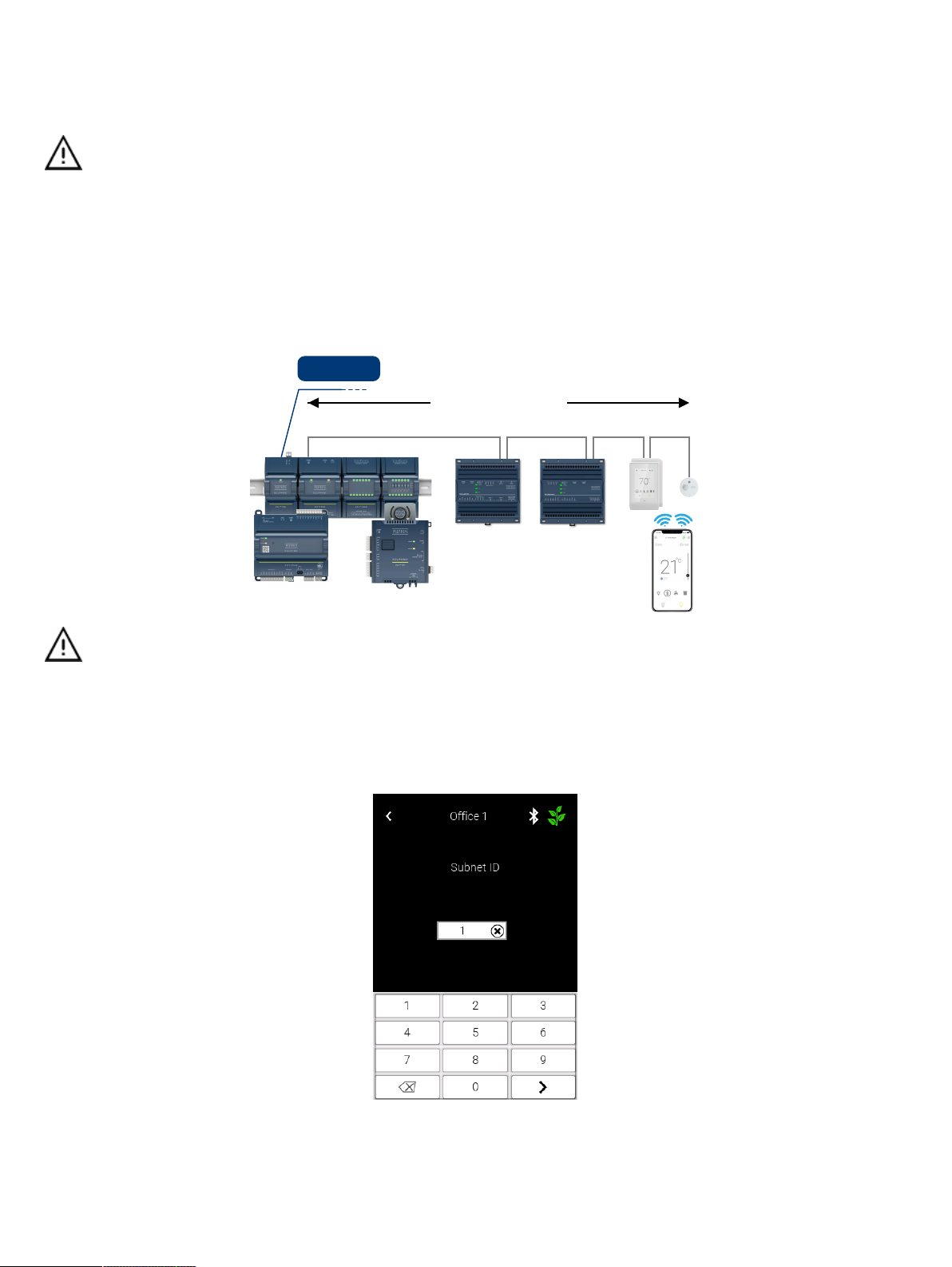
Subnet ID
If there are several devices being used on the same subnet, each device must be configured to have a unique subnet ID. The subnet ID can be changed
directly on screen from the UNITOUCH’s subnet ID configuration menu.
5 different Subnet ID codifications are used on the subnetwork :
£1 for Allure UNITOUCH™ sensors and EC-Multi-Sensor-BLE sensors
£1 for Allure EC-Smart-Vue sensors
£1 for Allure EC-Smart-Comfort and Allure EC-Smart-Air sensors
£1 for EC-Multi-Sensors
£1 for ECx-Light/Blind expansion modules
Consequently, for example, the same Subnet ID can be assigned to an ECx-Light/Blind module, to an EC-Multi-Sensor and to an Allure EC-
Smart-Vue sensor without any addressing issue.
Bluetooth Low Energy Smart Room Control Subnetwork
The Allure UNITOUCH can be freely combined in a daisy chain configuration.
BACnet/IP
Subnetwork: Cat 5e Cable with RJ-45 Connectors
100 m (328 ft) Maximum Length
A mixed architecture with standard room devices and Bluetooth low energy enabled devices is not recommended.
Changing the Subnet ID
Each device on the subnet requires a unique subnet ID. If a connected device’s subnet ID does not match its programmed ID, or if two or more devices
have the same subnet ID, there will be a communication error. A communication error screen will be displayed and you will be prompted to enter the de-
fault password (9995) to access the subnet ID settings.

7 / 7 UNITOUCH_IG_14_EN
Maintenance and Cleaning
Gently clean the device with a soft, lint-free cloth slightly moistened with a solution of mild liquid dish soap and warm water or disinfect the device with a
soft cloth slightly moistened with a 70% isopropyl alcohol.
Do not directly spray any liquid or disinfecting solution on the device. Do not clean with any other chemicals products.
Disposal
The Waste Electrical and Electronic Equipment (WEEE) Directive set out regulations for the recycling and disposal of products. The WEEE2002/96/EG
Directive applies to standalone products, for example, products that can function entirely on their own and are not a part of another system or piece of
equipment.
For this reason Distech Controls products are exempt from the WEEE Directive. Nevertheless, Distech Controls products are marked with the WEEE
symbol , indicating devices are not to be thrown away in municipal waste.
Products must be disposed of at the end of their useful life according to local regulations and the WEEE Directive.
FCC Statement
Changes or modifications not expressly approved by Distech Controls could void the user's authority to operate the equipment.
This equipment has been tested and found to comply with the limits for a Class B digital device, pursuant to Part 15 of the FCC Rules.
These limits are designed to provide reasonable protection against harmful interference in a residential installation. This equipment
generates, uses and can radiate radio frequency energy and, if not installed and used in accordance with the instructions, may cause
harmful interference to radio communications. However, there is no guarantee that interference will not occur in a particular installation. If
this equipment does cause harmful interference to radio or television reception, which can be determined by turning the equipment off and
on, the user is encouraged to try to correct the interference by one or more of the following measures:
£Reorient or relocate the receiving antenna.
£Increase the separation between the equipment and receiver.
£Connect the equipment into an outlet on a circuit different from that to which the receiver is connected.
£Consult the dealer or an experienced radio/TV technician for help.
This device complies with Part 15 of the FCC rules and with Industry Canada’s license exempt RSS. Operation is subject to the following
two conditions:
£This device may not cause harmful interference, and
£This device must accept any interference received, including interference that may cause undesired operation of the device.
Specifications subject to change without notice.
ECLYPSE, Distech Controls, the Distech Controls logo, EC-Net, Allure, and Allure UNITOUCH are trademarks of Distech Controls Inc. BACnet is a registered trademark of ASHRAE; BTL is a registered
trademark of the BACnet Manufacturers Association. The Bluetooth® word mark and logos are registered trademarks owned by Bluetooth SIG, Inc. and any use of such marks is under license. All other
trademarks are property of their respective owners.
©, Distech Controls Inc., 2015 - 2022 All rights reserved.
Global Head Office - 4205 place de Java, Brossard, QC, Canada, J4Y 0C4 - EU Head Office - ZAC de Sacuny, 558 avenue Marcel Mérieux, 69530 Brignais, France
Other manuals for Allure UNITOUCH
1
Table of contents
Other Distech Controls Accessories manuals

Distech Controls
Distech Controls Allure EC-Sensor Series Manual

Distech Controls
Distech Controls HS-THX User manual

Distech Controls
Distech Controls Allure EC-Smart-Air Series User manual

Distech Controls
Distech Controls GS-AQR Manual

Distech Controls
Distech Controls UNIWAVE User manual

Distech Controls
Distech Controls EC-Multi-Sensor-BLE User manual

Distech Controls
Distech Controls Allure EC-Smart-Vue Series User manual

Distech Controls
Distech Controls EC-Multi-Sensor Series Manual


