SICK GTE2 Flat User manual

OPERATING INSTRUCTION
GTE2 Flat
Miniature photoelectric sensors

Described product
G2F
GTE2F
Manufacturer
SICK AG
Erwin-Sick-Str. 1
79183 Waldkirch
Germany
Production location
SICK Product Center Asia Pte. Ltd.
Singapore
www.sick.com.sg
Legal information
This work is protected by copyright. Any rights derived from the copyright shall be
reserved for SICK AG. Reproduction of this document or parts of this document is only
permissible within the limits of the legal determination of Copyright Law. Any modifica‐
tion, abridgment or translation of this document is prohibited without the express writ‐
ten permission of SICK AG.
The trademarks stated in this document are the property of their respective owner.
© SICK AG. All rights reserved.
Original document
This document is an original document of SICK AG.
2006/42/EC
NO
SAFETY
8025415 | SICK
Subject to change without notice 3

Contents
1 General safety notes......................................................................... 5
2 Notes on UL approval........................................................................ 5
3 Intended use...................................................................................... 5
4 Operating and status indicators...................................................... 5
5 Mounting............................................................................................. 6
6 Electrical installation........................................................................ 6
7 Commissioning.................................................................................. 7
8 Troubleshooting................................................................................. 8
9 Disassembly and disposal............................................................... 9
10 Maintenance...................................................................................... 9
11 Technical specifications................................................................... 10
11.1 Dimensional drawing................................................................................ 10
11.2 Light spot diameter................................................................................... 11
CONTENTS
48025415 | SICK
Subject to change without notice

1 General safety notes
■Read the operating instructions before commissioning.
■
Connection, mounting, and configuration may only be performed by trained
specialists.
■
2006/42/EC
NO
SAFETY
Not a safety component in accordance with the EU Machinery Directive.
■
When commissioning, protect the device from moisture, contamination and
UV radiation (sun light).
■These operating instructions contain information required during the life cycle of
the sensor.
2 Notes on UL approval
The device must be supplied by a Class 2 source of supply.
UL Environmental Rating: Enclosure type 1
3 Intended use
The GTE2F is an opto-electronic photoelectric proximity sensor (referred to as “sensor”
in the following) for the optical, non-contact detection of objects, animals, and persons.
If the product is used for any other purpose or modified in any way, any warranty claim
against SICK AG shall become void.
4 Operating and status indicators
Energetic photoelectric proximity sensor.
12
Figure 1: Dimensional drawing
GENERAL SAFETY NOTES 1
8025415 | SICK
Subject to change without notice 5

1LED indicator green: supply voltage active
2LED indicator yellow: status of received light beam
5 Mounting
Mount the sensor using a suitable mounting bracket (see the SICK range of acces‐
sories).
Note the sensor's maximum permissible tightening torque of 0.1 Nm.
6 Electrical installation
The sensors must be connected in a voltage-free state (UV = 0 V). The following informa‐
tion must be observed, depending on the connection type:
– Plug connection: note pin assignment: when the lid is open, the male connector
can be swiveled horizontally and vertically.
– Cable: wire color
Only apply voltage/switch on the voltage supply (UV > 0 V) once all electrical connec‐
tions have been established.
Explanation of the connection diagram (Tables pin assignment):
Q = switching outputs
n. c. = not connected
DC: 10 ... 30 V DC
Table 1: Pin assignment
GXX2F(S)
-X14xx
-X54xx
1BN + (L+) + (L+)
2- - -
3BU - (M) - (M)
4BK Q Q
BK: 0.1 mm2, AWG30
BU+BN: 0.127 mm2, AWG28
2
1
4
3
5 MOUNTING
68025415 | SICK
Subject to change without notice

Table 2: Switching output
PNP Q
(≤ 50 mA)
+ (L+)
Q
– (M)
+ (L+)
Q
– (M)
Q
(≤ 50 mA)
+ (L+)
Q
– (M)
+ (L+)
Q
– (M)
NPN Q
(≤ 50 mA)
+ (L+)
Q
– (M)
+ (L+)
Q
– (M)
Q
(≤ 50 mA)
+ (L+)
Q
– (M)
+ (L+)
Q
– (M)
7 Commissioning
1Alignment
Align sensor on object. Select the position so that the red emitted light beam hits the cen‐
ter of the object. You must ensure that the optical opening (front screen) of the sensor is
completely clear.
ELECTRICAL INSTALLATION 6
8025415 | SICK
Subject to change without notice 7

Figure 2: Alignment
Figure 3: Alignment 2
2Sensing range
0
Sensing range
1
2
3
Sensing range typ. max.
4
(0.16) 8
(0.31) 12
(0.47)
311
15
Distance in mm (inch)
12.5
1.5
2
9
3.5
16
(0.63)
763.5/4.5
Figure 4: Sensing range 15 mm
0
Sensing range
1
2
3
Sensing range typ. max.
10
(0.39)
5
(0.20) 15
(0.59) 20
(0.79) 25
(0.98)
220
30
Distance in mm (inch)
2512
15
3
30
(1.18)
151154
Figure 5: Sensing range 30 mm
1Sensing range on white, 90 % remission
2Sensing range on gray, 18 % remission
3Sensing range on black, 6 % remission
Use see table 2, page 7 to check the function. If the switching output fails to behave in
accordance with the table, check the application conditions. See section Fault diagnosis.
3Sensing range setting
Sensor which it is not possible to set: The sensor is adjusted and ready for operation.
8 Troubleshooting
The Troubleshooting table indicates measures to be taken if the sensor stops working.
Table 3: Troubleshooting
LED indicator/fault pattern Cause Measures
Yellow LED does not light up
even though the light beam is
aligned to the object and the
object is within the set sensing
range
No voltage or voltage below
the limit values
Check the power supply,
check all electrical connec‐
tions (cables and plug connec‐
tions)
Voltage interruptions Ensure there is a stable power
supply without interruptions
8 TROUBLESHOOTING
88025415 | SICK
Subject to change without notice

LED indicator/fault pattern Cause Measures
Sensor is faulty If the power supply is OK,
replace the sensor
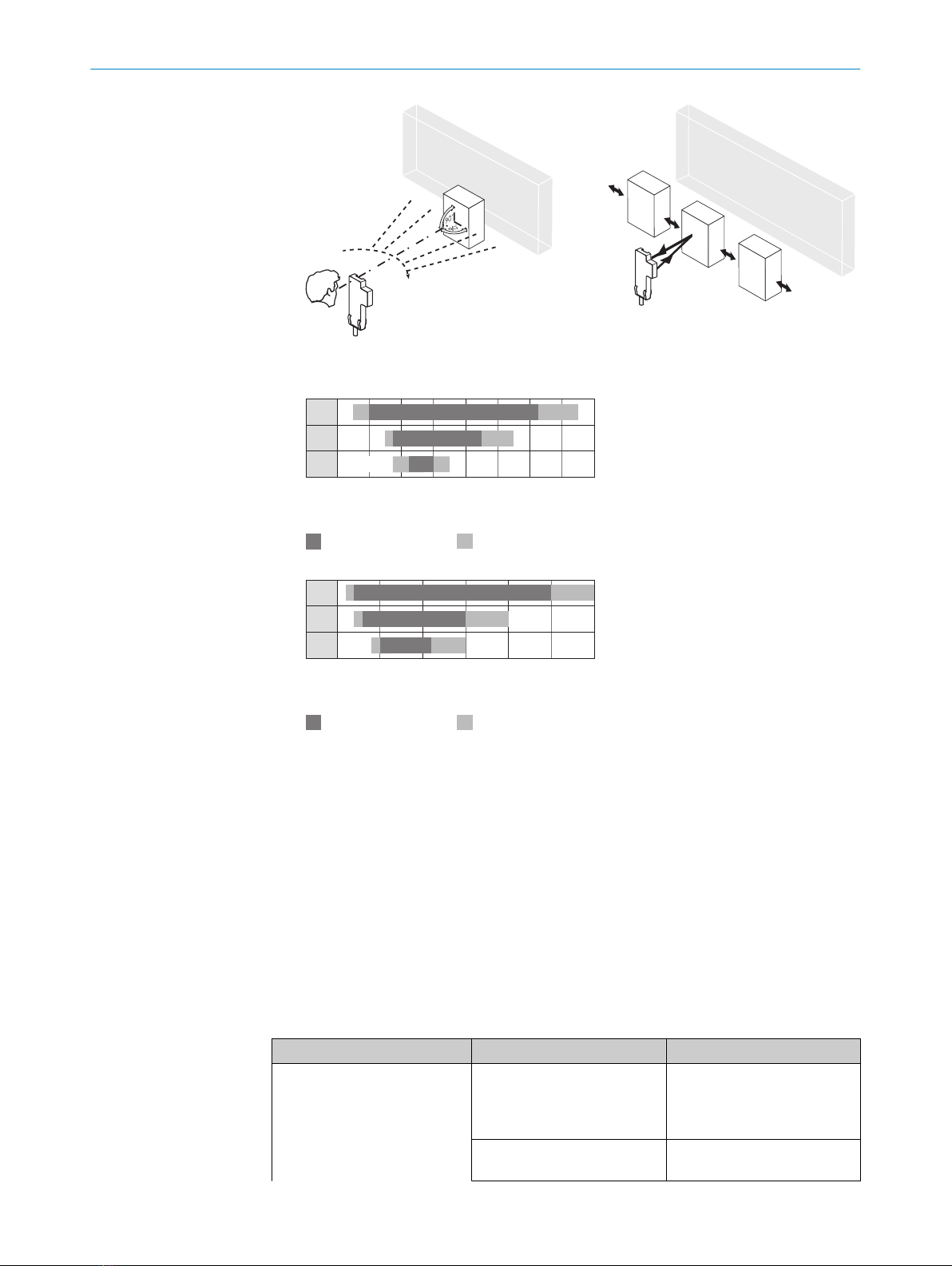
Yellow LED lights up, no object
in the path of the beam
Excessive background remis‐
sion
Check changes to the back‐
ground. Reduce the sensitivity
of the sensor or use sensors
with background suppression
Object is in the path of the
beam, yellow LED does not
light up
Sensitivity is set too low or dis‐
tance between the sensor and
the object is too long
Increase the sensing range,
take note of the distance
between the sensor and the
background
Object is in the path of the
beam, yellow LED does not
light up
Remission capability of the
object is insufficient
Increase the sensing range,
take note of the distance
between the sensor and the
background
9 Disassembly and disposal
The sensor must be disposed of according to the applicable country-specific regula‐
tions. Efforts should be made during the disposal process to recycle the constituent
materials (particularly precious metals).
NOTE
Disposal of batteries, electric and electronic devices
•According to international directives, batteries, accumulators and electrical or
electronic devices must not be disposed of in general waste.
•The owner is obliged by law to return this devices at the end of their life to the
respective public collection points.
•
WEEE: This symbol on the product, its package or in this document, indi‐
cates that a product is subject to these regulations.
10 Maintenance
SICK sensors are maintenance-free.
We recommend doing the following regularly:
•Clean the external lens surfaces
•Check the screw connections and plug-in connections
No modifications may be made to devices.
Subject to change without notice. Specified product properties and technical data are
not written guarantees.
DISASSEMBLY AND DISPOSAL 9
8025415 | SICK
Subject to change without notice 9

11 Technical specifications
GTE2F-Xxx11 GTE2F-Xxx31
Sensing range 2 ... 12.5 mm 2 ... 25 mm
Sensing range max. 1.5 ... 15 mm1) 1 ... 30 mm1)
Light spot diameter/distance 7.5 mm / 10 mm 5.5 mm / 15 mm
Supply voltage UBDC 10 ... 30 V2) DC 10 ... 30 V2)
Output current Imax.≤ 50 mA ≤ 50 mA
Switching frequency 800 Hz3) 800 Hz3)
Max. response time ≤ 0.625 ms4) ≤ 0.625 ms4)
Enclosure rating IP67 IP67
Protection class III III
Circuit protection A, C, D5) A, C, D5)
Ambient operating temperature -20 °C ... +50 °C -20 °C ... +50 °C
1) Object with 90 % remission (based on standard white DIN 5033)
2) Limit value; residual ripple max. 5 Vss
3) With light / dark ratio 1:1
4) Signal transit time with resistive load
5) A = UB-connections reverse polarity protected
C = Interference suppression
D = outputs overcurrent and short-circuit protected
11.1 Dimensional drawing
24 (0.94)
4.5 (0.18)
11 (0.43)1 (0.04)
14 (0.55)
1 (0.04)5.5 (0.22) 3.5 (0.14)
Ø 2.2
(0.09)
2.2
(0.09)
Ø 2.3
(0.09)
Figure 6: Dimensional drawing GTE2F
11 TECHNICAL SPECIFICATIONS
10 8025415 | SICK
Subject to change without notice

11.2 Light spot diameter
Ø 11
(0.43)
Ø 5
(0.20) Ø 7.5
(0.30)
Sensor
0 15
(0.59)
10
(0.39)
5
(0.2)
Distance in mm (inch)
Diameter in mm (inch)
Figure 7: GTE2F, 15 mm version
Ø 11
(0.43)
Ø 3
(0.12) Ø 5.5
(0.22)
Sensor
0 30
(1.18)
15
(0.59)
8
(0.31)
Distance in mm (inch)
Diameter in mm (inch)
Figure 8: GTE2F, 30 mm version
TECHNICAL SPECIFICATIONS 11
8025415 | SICK
Subject to change without notice 11

Beschriebenes Produkt
G2F
Hersteller
SICK AG
Erwin-Sick-Str. 1
79183 Waldkirch
Deutschland
Fertigungsstandort
SICK Product Center Asia Pte. Ltd.
Singapore
www.sick.com.sg
Rechtliche Hinweise
Dieses Werk ist urheberrechtlich geschützt. Die dadurch begründeten Rechte bleiben
bei der Firma SICK AG. Die Vervielfältigung des Werks oder von Teilen dieses Werks ist
nur in den Grenzen der gesetzlichen Bestimmungen des Urheberrechtsgesetzes zuläs‐
sig. Jede Änderung, Kürzung oder Übersetzung des Werks ohne ausdrückliche schriftli‐
che Zustimmung der Firma SICK AG ist untersagt.
Die in diesem Dokument genannten Marken sind Eigentum ihrer jeweiligen Inhaber.
© SICK AG. Alle Rechte vorbehalten.
Originaldokument
Dieses Dokument ist ein Originaldokument der SICK AG.
2006/42/EC
NO
SAFETY
8025415 | SICK
Subject to change without notice 13

Inhalt
12 Allgemeine Sicherheitshinweise..................................................... 15
13 Hinweise zur UL Zulassung.............................................................. 15
14 Bestimmungsgemäße Verwendung............................................... 15
15 Betriebs- und Statusanzeigen.......................................................... 15
16 Montage.............................................................................................. 15
17 Elektrische Installation..................................................................... 15
18 Inbetriebnahme................................................................................. 16
19 Störungsbehebung............................................................................ 16
20 Demontage und Entsorgung............................................................ 17
21 Wartung.............................................................................................. 17
22 Technische Daten.............................................................................. 18
22.1 Maßzeichnung........................................................................................... 18
22.2 Lichtfleckdurchmesser............................................................................. 18
INHALT
14 8025415 | SICK
Subject to change without notice

12 Allgemeine Sicherheitshinweise
■Lesen Sie vor der Inbetriebnahme des Geräts die Betriebsanleitung.
■
Der Anschluss, die Montage und die Konfiguration des Geräts dürfen nur
von geschultem Fachpersonal vorgenommen werden.
■
2006/42/EC
NO
SAFETY
Bei diesem Gerät handelt es sich um kein sicherheitsgerichtetes Bauteil im
Sinne der EU-Maschinenrichtlinie.
■
Bei der Inbetriebnahme ist das Gerät ausreichend vor Feuchtigkeit, Ver‐
schmutzung und UV-Strahlung (Sonnenlicht) zu schützen.
■Die vorliegende Betriebsanleitung enthält Informationen, die während des Lebens‐
zyklus der Lichtschranke benötigt werden.
13 Hinweise zur UL Zulassung
The device must be supplied by a Class 2 source of supply.
UL Environmental Rating: Enclosure type 1
14 Bestimmungsgemäße Verwendung
Die GTE2F ist ein optoelektronischer Reflexions-Lichttaster (im Folgenden Sensor
genannt) und wird zum optischen, berührungslosen Erfassen von Sachen, Tieren und
Personen eingesetzt. Bei jeder anderen Verwendung und bei Veränderungen am Pro‐
dukt verfällt jeglicher Gewährleistungsanspruch gegenüber der SICK AG.
15 Betriebs- und Statusanzeigen
Energetischer Reflexions-Lichttaster.
16 Montage
Den Sensor unter Verwendung eines geeigneten Befestigungswinkels montieren (siehe
SICK-Zubehörpalette).
Beachten Sie das maximal zulässige Anzugsdrehmoment von 0.1 Nm.
17 Elektrische Installation
Anschluss der Sensoren muss spannungsfrei (UV = 0 V) erfolgen. Je nach Anschlussart
sind die folgenden Informationen zu beachten:
– Steckeranschluss: Steckerbelegung beachten: Bei geöffnetem Deckel kann der
Steckverbinder horizontal und vertikal geschwenkt werden.
– Leitung: Aderfarbe
Erst nach Anschluss aller elektrischen Verbindungen die Spannungsversorgung (UV
> 0 V) anlegen bzw. einschalten.
ALLGEMEINE SICHERHEITSHINWEISE 12
8025415 | SICK
Subject to change without notice 15

Erläuterungen zum Anschlussschema (Tabelle Steckerbelegung):
Q = Schaltausgänge
n. c. = unbeschaltet
DC: 10 ... 30 V DC1
1Grenzwerte; Betrieb in kurzschlussgeschütztem Netz max. 8A
18 Inbetriebnahme
1Ausrichtung
Richten Sie den Sensor auf das Objekt aus. Wählen Sie die Position so, dass der rote Sen‐
delichtstrahl ins Zentrum des Objekts trifft. Stellen Sie sicher, dass die Optiköffnung (Front‐
scheibe) des Sensors vollständig frei ist.
2Schaltabstand
Mithilfe "Abbildung X" die Funktion überprüfen. Wenn sich die Schaltausgänge nicht ent‐
sprechend der Tabelle verhalten, die Einsatzbedingungen prüfen. Siehe Abschnitt zur Feh‐
lerdiagnose.
3Einstellung Schaltabstand
Sensor ohne Einstellmöglichkeit: Sensor ist eingestellt und betriebsbereit.
19 Störungsbehebung
Tabelle Störungsbehebung zeigt, welche Maßnahmen durchzuführen sind, wenn die
Funktion des Sensors nicht mehr gegeben ist.
Tabelle 4: Fehlerbehebung
Anzeige-LED / Fehlerbild Ursache Maßnahme
gelbe LED leuchtet nicht,
obwohl der Lichtstrahl auf das
Objekt ausgerichtet ist, und
das Objekt innerhalb des ein‐
gestellten Schaltabstandes ist
keine Spannung oder Span‐
nung unterhalb der Grenz‐
werte
Spannungsversorgung prüfen,
den gesamten elektrischen
Anschluss prüfen (Leitungen
und Steckerverbindungen)
Spannungsunterbrechungen Sicherstellen einer stabilen
Spannungsversorgung ohne
Unterbrechungen
Sensor ist defekt Wenn Spannungsversorgung
in Ordnung ist, dann Sensor
austauschen
gelbe LED leuchtet, kein Objekt
im Strahlengang
Remissionsvermögen des Hin‐
tergrundes zu hoch
Veränderungen des Hinter‐
grundes prüfen. Empfindlich‐
keit des Sensors reduzieren
oder Taster mit Hintergrund‐
ausblendung verwenden
Objekt ist im Strahlengang,
gelbe LED leuchtet nicht
Empfindlichkeit ist zu gering
eingestellt oder Abstand zwi‐
schen Sensor und Objekt ist
zu groß
Schaltabstand vergrößern,
Abstand zwischen Sensor und
Hintergrund beachten
Objekt ist im Strahlengang,
gelbe LED leuchtet nicht
Remissionsvermögen des
Objektes ist zu gering
Schaltabstand vergrößern,
Abstand zwischen Sensor und
Hintergrund beachten
17 ELEKTRISCHE INSTALLATION
16 8025415 | SICK
Subject to change without notice

20 Demontage und Entsorgung
Die Lichtschranke muss entsprechend den geltenden länderspezifischen Vorschriften
entsorgt werden. Bei der Entsorgung sollte eine werkstoffliche Verwertung (insbeson‐
dere der Edelmetalle) angestrebt werden.
HINWEIS
Entsorgung von Batterien, Elektro- und Elektronikgeräten
•Gemäß den internationalen Vorschriften dürfen Batterien, Akkus sowie Elektro-
und Elektronikgeräte nicht mit dem Hausmüll entsorgt werden.
•Der Besitzer ist gesetzlich verpflichtet, diese Geräte am Ende ihrer Lebensdauer
bei den entsprechenden öffentlichen Sammelstellen abzugeben.
•
WEEE: Dieses Symbol auf dem Produkt, dessen Verpackung oder im vor‐
liegenden Dokument gibt an, dass ein Produkt den genannten Vorschriften unter‐
liegt.
21 Wartung
SICK-Sensoren sind wartungsfrei.
Wir empfehlen, in regelmäßigen Abständen
•die optischen Grenzflächen zu reinigen
•Verschraubungen und Steckverbindungen zu überprüfen
Veränderungen an Geräten dürfen nicht vorgenommen werden.
Irrtümer und Änderungen vorbehalten. Angegebene Produkteigenschaften und techni‐
sche Daten stellen keine Garantieerklärung dar.
DEMONTAGE UND ENTSORGUNG 20
8025415 | SICK
Subject to change without notice 17

22 Technische Daten
GTE2F-Xxx11 GTE2F-Xxx31
Schaltabstand 2 ... 12.5 mm 2 ... 25 mm
Schaltabstand max. 1.5 ... 15 mm21 ... 30 mm2
Lichtfleckdurchmesser/Entfernung 7.5 mm / 10 mm 5.5 mm / 15 mm
Versorgungsspannung UBDC 10 ... 30 V3DC 10 ... 30 V3
Ausgangsstrom Imax.≤ 50 mA ≤ 50 mA
Schaltfrequenz 800 Hz6800 Hz6
Ansprechzeit max. ≤ 0.625 ms7≤ 0.625 ms7
Schutzart IP67 IP67
Schutzklasse III9III9
Schutzschaltungen A, C, D11 A, C, D11
Betriebsumgebungstemperatur -20 °C ... +50 °C -20 °C ... +50 °C
1Für einen zuverlässigen Betrieb empfehlen wir die Verwendung von Feintripel-Reflektoren oder Reflexionsfolie. Geeignete Reflektoren und
Folien finden Sie im Zubehör-Programm von Sick. Die Verwendung von Reflektoren mit großer Tripelstruktur kann die Funktionsfähigkeit
beeinträchtigen.
2Tastgut mit 90 % Remission (bezogen auf Standard-Weiß DIN 5033)
3Grenzwerte; Betrieb im kurzschlussgeschützten Netz max. 8 A; Restwelligkeit max. 5 Vss
5Gebrauchskategorie: AC-15, DC-13 (EN 60947-1)
6Mit Hell- / Dunkelverhältnis 1:1
7Signallaufzeit bei ohmscher Last
8gültig für Q\ auf Pin2, wenn per Software konfiguriert
9Bemessungsspannung DC 50 V
11 A = UB-Anschlüsse verpolsicher
C = Störimpulsunterdrückung
D = Ausgänge überstrom- und kurzschlussfest
22.1 Maßzeichnung
22.2 Lichtfleckdurchmesser
Ø 11
Ø 5 Ø 7,5
Sensor
0 15105
Abstand in mm
Durchmesser in mm
Abbildung 9: GTE2F, 15 mm version
22 TECHNISCHE DATEN
18 8025415 | SICK
Subject to change without notice

Ø 11
Ø 3 Ø 5,5
Sensor
0 30158
Abstand in mm
Durchmesser in mm
Abbildung 10: GTE2F, 30 mm version
TECHNISCHE DATEN 22
8025415 | SICK
Subject to change without notice 19
Table of contents
Languages:
Other SICK Accessories manuals

SICK
SICK deTem4 Core A/P User manual

SICK
SICK HTE18 Series User manual

SICK
SICK RMS1000 User manual

SICK
SICK Bluetooth WLA16 User manual

SICK
SICK GTB2 Flat Series User manual

SICK
SICK T-EASIC FTS User manual

SICK
SICK GRSE18V User manual

SICK
SICK safeVisionary2 User manual

SICK
SICK SureSense HSE18 Series User manual

SICK
SICK PowerProx WTT12L User manual