Image Sensing Systems RTMS G4 User manual


Copyright 2008-2009 ISS Canada. All Rights Reserved.
No part of this document may be reproduced or quoted without written permission from Image
Sensing Systems, Inc.
Windows is a registered trademark of Microsoft Corporation. IBM PC is a registered
trademark of International Business Machines.
All other product names are trademarks or registered trademarks of their respective owners.
b © 2009 Image Sensing Systems, Inc. G4 User Manual

Table of Contents
CHAPTER 1 ABOUT THE G4 SYSTEM ............................................................................... 1-1
REVISION HISTORY....................................................................................................................... 1-1
WARRANTY................................................................................................................................... 1-1
CAUTION .................................................................................................................................... 1-1
SERVICE ........................................................................................................................................ 1-1
PREREQUISITES ............................................................................................................................. 1-2
IMPORTANT SAFETY INFORMATION.............................................................................................. 1-2
CONTACT ISS CANADA................................................................................................................. 1-3
BRIEF DESCRIPTION...................................................................................................................... 1-3
SCOPE OF THIS DOCUMENT .......................................................................................................... 1-4
INSPECT YOUR SHIPMENT FROM ISS CANADA............................................................................. 1-4
RTMS OPTIONS ............................................................................................................................ 1-5
THE STANDARD RTMS G4 MODEL K4 OFFERS THE FOLLOWING:................................................ 1-5
INTRODUCTION TO THE RTMS ..................................................................................................... 1-5
VEHICLE DETECTION .................................................................................................................... 1-6
CHAPTER 2 RTMS G4 INSTALLATION ............................................................................. 2-1
SIDE-FIRED MOUNTING AND AIMING........................................................................................... 2-1
SET-BACK HEIGHT DIAGRAMS..................................................................................................... 2-3
ZERO SETBACK OPTIONS .............................................................................................................. 2-3
CABLING ....................................................................................................................................... 2-4
Surge Suppression..................................................................................................................... 2-4
The RTMS Cable....................................................................................................................... 2-4
Preparing a Cable..................................................................................................................... 2-4
Connecting a Cable to the RTMS.............................................................................................. 2-5
MS CONNECTOR PIN-OUT ............................................................................................................ 2-5
STANDARD RS-232 PORT WIRING................................................................................................ 2-7
THE RS-485 PORT......................................................................................................................... 2-8
THE TCP/IP PORT WITH RS-232................................................................................................... 2-9
THE TCP/IP PORT WITH RS-485................................................................................................... 2-9
DUAL RS-232 PORTS .................................................................................................................. 2-10
CONTACT CLOSURE .................................................................................................................... 2-11
RS-485 MULTI-DROP.................................................................................................................. 2-11
WIRING NOTES............................................................................................................................ 2-11
RTMS TROUBLESHOOTING GUIDE............................................................................................. 2-12
RTMS TECHNICAL SPECIFICATIONS........................................................................................... 2-13
MICROWAVE SIGNAL AND COVERAGE AREA............................................................................. 2-13
ACCURACY OF MEASUREMENT &ERROR RATES....................................................................... 2-13
*Accuracy Performance Conditions....................................................................................... 2-13
MECHANICAL.............................................................................................................................. 2-14
POWER REQUIREMENTS &CONSUMPTION ................................................................................. 2-14
INTERFACES ................................................................................................................................2-14
UPGRADE CAPABILITY................................................................................................................ 2-15
SURGE IMMUNITY....................................................................................................................... 2-15
G4 User Manual © 2009 ISS Canada. i

Table of Contents
ENVIRONMENTAL CONDITIONS .................................................................................................. 2-15
ELECTROMAGNETIC INTERFERENCE........................................................................................... 2-15
RELIABILITY ............................................................................................................................... 2-15
RECOMMENDED SURGE PROTECTION......................................................................................... 2-16
CHAPTER 3 G4 SOFTWARE.................................................................................................. 3-1
REFERENCE................................................................................................................................... 3-1
RTMS System Requirements...................................................................................................... 3-1
About The RTMS Setup Utility.................................................................................................. 3-1
Communication......................................................................................................................... 3-1
PROCEDURES................................................................................................................................. 3-1
MICROSOFT .NET RUNTIME WARNINGS ...................................................................................... 3-2
HOW TO NAVIGATE THE RTMS INTERFACE................................................................................. 3-3
GET STARTED ............................................................................................................................... 3-4
ESTABLISH A CONNECTION WITH THE RTMS HARDWARE .......................................................... 3-4
HOW TO RUN WINRTMS IN DEMO MODE ................................................................................... 3-5
HOW TO MODIFY OR TROUBLESHOOT THE CONNECTION WITH THE RTMS HARDWARE............ 3-7
HOW TO SET UP SERIAL COMMUNICATION.................................................................................. 3-9
HOW TO SET UP DSS.................................................................................................................. 3-10
HOW TO SET UP TCP/IP COMMUNICATIONS ............................................................................. 3-14
HOW TO CONFIGURE THE IP SERVER.......................................................................................... 3-19
HOW TO USE THE AUTOMATIC SETUP WIZARD ......................................................................... 3-20
HOW TO FIX SPLASHING ............................................................................................................. 3-22
HOW TO ADJUST SENSITIVITY .................................................................................................... 3-23
HOW TO VERIFY COUNTS ........................................................................................................... 3-24
HOW TO MODIFY VEHICLE CLASSIFICATIONS............................................................................ 3-25
HOW TO UPGRADE FIRMWARE ................................................................................................... 3-26
HOW TO RECORD DATA.............................................................................................................. 3-27
X3 COMPATIBLE—STATISTICAL MESSAGE ............................................................................... 3-28
G4 STATISTICAL MESSAGE......................................................................................................... 3-28
HOW TO PERFORM AUTOMATIC SPEED CALIBRATION............................................................... 3-29
HOW TO PERFORM MANUAL CALIBRATION ............................................................................... 3-30
HOW TO CONFIGURE COMMON SETTINGS.................................................................................. 3-31
HOW TO SAVE A SETUP FILE TO THE HARD DISK....................................................................... 3-32
RTMS WORKSPACE.................................................................................................................... 3-33
RTMS TITLE BAR....................................................................................................................... 3-34
RTMS STATUS BAR.................................................................................................................... 3-35
ABOUT RTMS MAIN SCREEN..................................................................................................... 3-36
RTMS MAIN SCREEN ................................................................................................................. 3-37
RTMS MANUAL SETUP .............................................................................................................. 3-38
RTMS APPLICATION OPTIONS.................................................................................................... 3-40
RTMS SENSITIVITY OPTIONS ..................................................................................................... 3-41
RTMS ZONE OPTIONS ................................................................................................................ 3-42
RTMS FINE TUNE OPTIONS........................................................................................................ 3-43
RTMS LABELING OPTIONS......................................................................................................... 3-44
RTMS MESSAGE PERIOD OPTIONS............................................................................................. 3-45
RTMS SENSOR ID OPTIONS........................................................................................................ 3-46
RTMS VERIFY COUNTS.............................................................................................................. 3-47
RTMS DATA OPTIONS................................................................................................................ 3-48
RTMS ADVANCED OPTIONS....................................................................................................... 3-49
RTMS ADVANCED CLASSIFICATION OPTIONS........................................................................... 3-50
ii © 2009 ISS Canada.. G4 User Manual

Table of Contents
RTMS CONTACT CLOSURES....................................................................................................... 3-51
RTMS DUAL LOOP OPTIONS ...................................................................................................... 3-52
RTMS FIRMWARE UPGRADE OPTIONS....................................................................................... 3-53
RTMS COMMUNICATION OPTIONS............................................................................................. 3-54
PC SERIAL COMMUNICATION OPTIONS...................................................................................... 3-54
RTMS COMMUNICATION OPTIONS…......................................................................................... 3-55
PC TCP/IP COMMUNICATION OPTIONS...................................................................................... 3-55
RTMS COMMUNICATION OPTIONS…......................................................................................... 3-56
RADIO MODEM COMMUNICATION OPTIONS............................................................................... 3-56
RTMS MESSAGE COMPOSITION OPTIONS.................................................................................. 3-58
RTMS FILE OPTIONS .................................................................................................................. 3-59
RTMS COMMON SETTINGS ........................................................................................................ 3-60
RTMS STATISTICS...................................................................................................................... 3-61
RTMS AUTOMATIC SPEED CALIBRATION.................................................................................. 3-62
RTMS MANUAL SPEED CALIBRATION....................................................................................... 3-63
RTMS INTERNAL MEMORY........................................................................................................ 3-64
RTMS SELF TEST ....................................................................................................................... 3-65
G4 User Manual © 2009 ISS Canada. iii

Table of Contents
iv © 2009 ISS Canada.. G4 User Manual

Chapter 1
About the G4 System
Revision History
Revisions to this document are as follows:
Issue No. Issue Date Issue Reason
Issue 5.0 May 2008 First issue of G4 product.
Issue 5.1 July 2008 New screenshots and organization.
Corrected information pertaining to G4.
Issue 5.2 December 2008 New documentation formation.
New information.
Corrections.
Issue 5.3 February 2009 New documentation formation.
New information.
Corrections.
Warranty
Image Sensing Systems Inc. warrants this product to be free from defects in material and
workmanship for a period of two years from date of delivery. Damage to the product due to
accident, abuse by the buyer, or unauthorized modification, improper installation, or operation
outside the specifications is not covered by the warranty.
Image Sensing Systems, Inc. warrants that its software and firmware designated for use with
the instrument will execute its programming instructions when properly installed. ISS does not
warrant that operation of software or firmware will be uninterrupted or error free.
CAUTION
Do not attempt to repair the RTMS unit. Such action will void the warranty. Contact ISS
Canada if the unit requires servicing.
Service
If your hardware or software fails to operate, please refer to the troubleshooting guides
provided with this documentation or call ISS technical support.
ISS Inc. will repair or replace at its option, any components, which prove to be defective
during the warranty period.
•Buyer shall pay for shipping charges to ISS.
•ISS will pay shipping charges and insurance for warranty repaired product.
•Buyer will be invoiced for repair and shipping of product repaired outside of warranty or
when no fault is found.
Units returned to ISS for service should include the following information with the shipment:
G4 User Manual © 2009 ISS Canada. 1-1

About the G4 System Chapter 1
•Name, address, and contact information of owner.
•Name and telephone number of someone familiar with the problem who may be contacted
by ISS personnel for further information if necessary.
•Model number, serial number and software revision number.
•A complete description of the problem. For example:
−Under what conditions did the problem occur?
−What equipment was attached?
−What was the result of the Self Test diagnostic?
•Shipping address for the return.
•Return Merchandise Authorization number. Contact ISS Customer Support prior to
shipping merchandise to obtain it.
The unit should be shipped in the original container. If the original container is unavailable,
there should be approximately one inch of packing material between the unit and inner carton.
For example: use plastic bubble-wrap. The carton should be sealed with strong tape or
strapping.
Prerequisites
If you are installing RTMS G4 hardware you must perform the following tasks:
•Choose an appropriate installation location.
•Manage your own personal safety and safety of other personnel.
•Assemble a list of the required equipment.
•Have experience creating cables.
If you are using the WinRTMS software you must perform the following tasks:
•Operate a mouse.
•Operate a keyboard.
•Start Windows.
•Install new software.
•Save and open file using Windows common file dialog.
Important Safety Information
Please review the following information before installation.
Warning
•READ ALL INSTRUCTIONS BEFORE USING
•HEED ALL WARNINGS IN THESE INSTRUCTIONS
•SAVE THESE INSTRUCTIONS FOR FUTURE REFERENCE
RTMS units must be installed and adjusted in accordance with the installation instructions
contained in this manual. Use the RTMS only for its intended purposes as described in this
manual. Changes or modifications not expressly approved by ISS Canada Ltd. could void the
user's authority to operate the equipment.
This equipment has been tested and found to comply with the
limits for a Class A digital device, pursuant to Part 15 of the
1-2 © 2009 ISS Canada. G4 User Manual

Chapter 1 About the G4 System
Note FCC Rules. These limits are designed to provide reasonable
protection against harmful interference when the equipment is
operated in a commercial environment. This equipment
generates, uses, and can radiate radio frequency energy and, if
not installed and used in accordance with the instruction
manual, may cause harmful interference to radio
communications. Operation of this equipment in a residential
area is likely to cause harmful interference in which case the
user will be required to correct the interference at their
expense.
Contact ISS Canada
Please contact ISS Canada with any questions or concerns about the RTMS or other ISS
Canada products, toll free at 1-800-668-9385. More information about our complete product
line is available on the web at www.imagesensingca.com.
Brief Description
The RTMS (Remote Traffic Microwave Sensor) measures the distance to objects in the path of
its microwave beam. This ranging capability allows it to detect moving and stationary vehicles
in multiple detection zones.
A single sensor can monitor traffic in up to 8-12 lanes. The sensor can be mounted on road-
side poles and aimed at a right angle to the road; this is referred to as the side-fired
configuration.
The internal processor calculates volume, occupancy, average speed and vehicle classifications
for each lane and transmits the information using its data ports and communication interfaces.
Optional contact closure outputs are also available for compatibility with loop based systems.
Caution
•For optimal accuracy, ISS Canada strongly recommends using ISS
Canada-trained personnel to install all RTMS-related products.
•ISS Canada also strongly recommends using ISS Canada-trained
personnel to survey installation sites for all RTMS-related products.
•For more information about our installation, surveying, and training
programs, contact ISS Canada at 1-800-668-9385.
Warning
Consult ISS Canada before using the RTMS or other RTMS-related
products for any purpose not expressly described in this manual or any
other RTMS product manual. Do not use the RTMS to control or
operate a gate-opening mechanism. Use of the RTMS for any
unauthorized purpose may cause injury to personnel or damage to
equipment.
G4 User Manual © 2009 ISS Canada. 1-3

About the G4 System Chapter 1
Scope of This Document
This documentation provides the following information for RTMS G4 sensor model K4:
•Setup
•Operation
•Troubleshooting
Software documentation for the RTMS Setup Utility 4.0 (also referred to as WinRTMS) is also
provided here.
•RTMS Setup Utility version 4.0 or greater is required for setup of RTMS G4 units with
firmware version 7.1 and later.
•This software is backwards compatible with all previous RTMS versions.
•Backward compatibility with older firmware is provided through WinRTMS version 3.6.
Inspect Your Shipment from ISS Canada
Please verify your RTMS shipment contains the following items:
•The RTMS sensor with lynch pin.
•Ball-joint mounting bracket; the vertical style is shipped by default; a horizontal style is
available on request.
•Connector kit consisting of :
−MS connector, female crimp pins, backshell, and pin insertion/extraction tool.
−DB-9F connector, female crimp pins and backshell.
−RJ-45 jack, if ordered with TCP/IP option.
•RTMS Setup Utility Software on CD.
•Whip antenna, if equipped with an internal modem (indicated by a label).
•Please notify ISS Canada immediately if the contents are incomplete or if there is
physical damage to any items in the shipment.
•Call toll free at 1-800-668-9385 or contact ISS Canada on the web at
www.imagesensingca.com.
1-4 © 2009 ISS Canada. G4 User Manual

Chapter 1 About the G4 System
RTMS Options
The standard RTMS G4 Model K4 offers the following:
•K-band (24.125 GHz)
•Low Voltage Power 12-24V AC or DC
•8MB Internal Data Storage Memory
•RS-232/485 Serial Interfaces
RTMS may be ordered with the following data communication options:
•Bluetooth Setup Wireless Interface
•Additional RS-232/422 Serial Interface
•Integrated Digital Spread Spectrum (DSS) Transceiver
•Integrated Cellular Modem: CDMA/GPRS/WiFi
•Integrated TCP/IP Ethernet Interface
•Integrated NTCIP 1209 Communications Protocol Module
•Integrated IP Video Camera
•Contact Closure for 8 and 16 Zones
The following power options are available:
•115V AC
Introduction to the RTMS
The RTMS G4 (Remote Traffic Microwave Sensor — 4th Generation) is a true RADAR
device, designed for traffic sensing applications. It measures the distance to objects in the path
of its microwave beam. The ranging capability allows the RTMS to detect stationary and
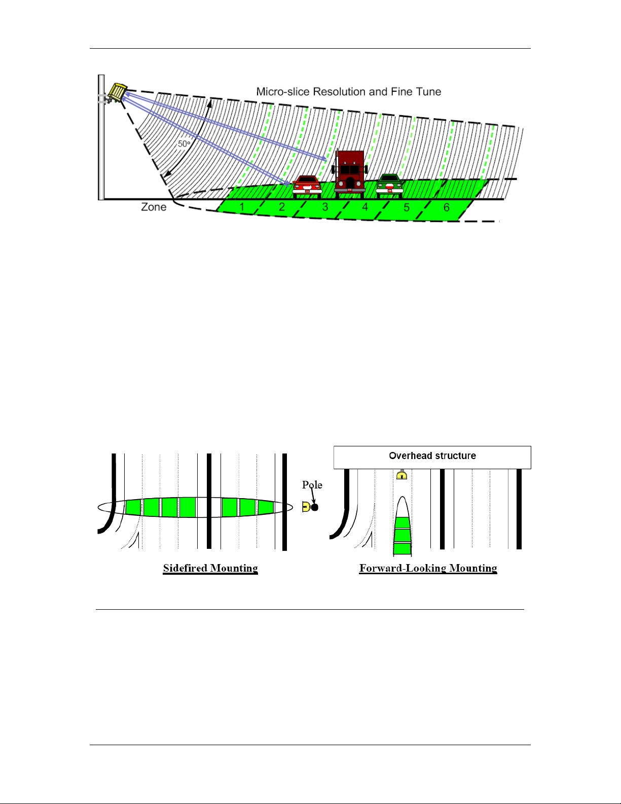
moving vehicles in multiple detection zones. When pointed onto a roadway, the RTMS
microwave beam projects an oval footprint. Its range is divided into multiple micro-slices, in
which vehicles are detected.
The RTMS receives reflected signals from all surfaces within its beam—pavement, barriers,
vehicles and trees. It maintains a background signal level from fixed objects in each micro-
slice. Vehicles are detected when their reflected signal exceeds the background level in their
micro-slice by a certain threshold level. If that detection is part of a defined zone, its contact
(optional) is closed during the detection time to indicate detection and internal counters are
incremented. Statistical measurements are available through two ports, including optional IP
and Radio modems.
G4 User Manual © 2009 ISS Canada. 1-5
About the G4 System Chapter 1
Figure 1.1. RTMS Microwave and Beam Footprint
Several operating modes optimize internal parameter settings for highway and intersection
applications. Two mounting configurations are possible: side-fired and forward-looking.
In side-fired mounting:
•The RTMS is located on a roadside pole and is aimed perpendicular to the traffic lanes.
•Micro-slices corresponding to the location of traffic lanes are allocated as detection zones
during the setup process.
•Each detection zone consists of multiple micro-slices.
•The length of the detection zone is determined by the width of the beam's footprint.
In forward-looking mounting:
•The RTMS is mounted on an overhead structure and is aimed along the center of the lane.
•In highway applications the sensor's aiming angle is adjusted to confine the footprint to
one or two lanes.
•The RTMS accurately measures vehicle speed and travel direction.
Figure 1.2. RTMS Mounting Configurations
Vehicle Detection
RTMS technology allows accuracy in the following conditions, even with a relatively low
mounting-height:
•Severe weather.
•Strong vibrations common to roadways that carry large vehicles.
•When vehicles are completely occluded by other vehicles.
1-6 © 2009 ISS Canada. G4 User Manual
Chapter 2
RTMS G4 Installation
Side-Fired Mounting and Aiming
The distance between the close edge of the first lane of traffic to be monitored and the front of
the structure on which the RTMS is mounted is referred to as set-back. Set-back is a limiting
installation parameter of RTMS. More lanes can be covered with a larger set-back.
Use the diagrams in Figures 2.1, 2.2, and 2.3 to determine the setback required to monitor a
given number of lanes. The correct installation height can be determined once the set-back is
calculated. Height is measured relative to the road surface of the detection area. Do not
measure height from the bottom of the mounting pole.
Example: For 3 lanes the minimum set-back should be 5 feet [1.5m].
Note
It is almost always better to be 20 feet [6 m] further back from the
minimum than 2 inches [5 cm] closer than the minimum. If real estate is
available, move the RTMS further back.
The mounting height is based on the setback. Using the correct height value
allows the RTMS to be aimed so that it receives maximum return signal
while covering all required lanes. Mounting the RTMS at an incorrect
height will reduce accuracy.
Median strips are equivalent to lanes and must be included in total lane
count. For example: an eight lane road with a two lane-wide median strip
has 10 equivalent lanes.
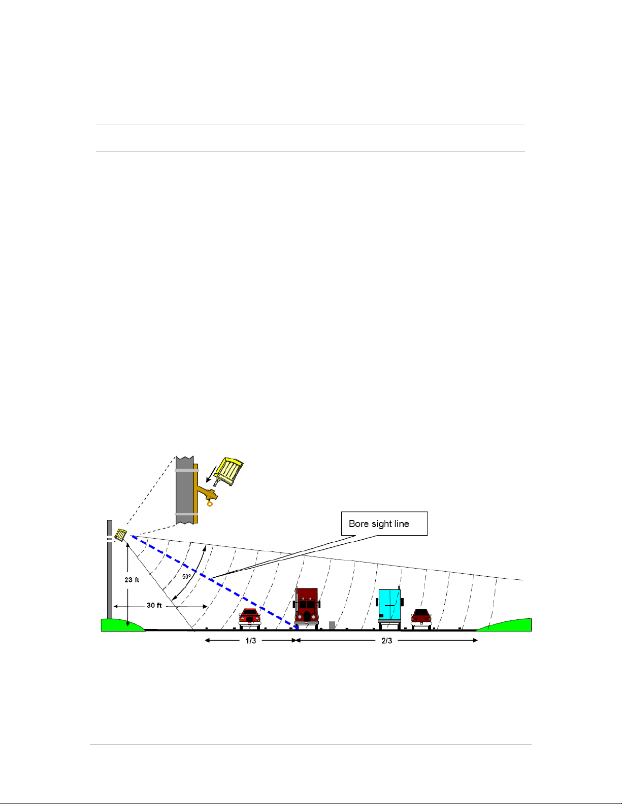
Figure 2.1. RTMS Aiming
G4 User Manual © 2009 Image Sensing Systems, Inc. 2-1

RTMS G4 Installation Chapter 2
Mounting and Aiming Procedure
Warning
Installation ISS Canada hardware may require that you work above the
ground on a ladder or bucket truck. Please make sure you have all the
required equipment and are aware of potential safety issues before
starting any installation. DO NOT install any RTMS hardware if you
are unsure how to complete the installation or lack appropriate safety
equipment. ISS Canada does not recommend installing this hardware
during inclement weather.
The following equipment is required to mount and aim the RTMS unit:
•Provided By ISS Canada. RTMS unit and its housing.
•Not Provided. Bolts or stainless steel banding. The bolt specifications depend on the
mounting requirements: for example, different bolts may be required when the RTMS unit
is mounted on a wooden pole than when the RTMS unit is mounted on a concrete wall.
•Provided By ISS Canada. Lynch pin
•Not Provided. 7/16" wrench, 1/2" wrench, assorted tools to be determined by mounting
specifications.
To mount and aim the RTMS unit:
1. Attach the bracket to the roadside pole (or another specified location) using bolts or
stainless steel banding.
2. Secure the RTMS to the mounting bracket by inserting the lynch pin.
3. Aim the RTMS as indicated on the diagram above. A 7/16" wrench is required to
release/tighten the ball-joint bolt.
4. Adjust the RTMS to be perpendicular to the travel lanes and level side to side.
5. Look from behind the unit and use the top sight-ridge as a guide to align the bore sight.
6. Tilt so that the top of the RTMS is aimed to the first 1/3 of the monitored lanes.
7. Secure the position by tightening the bolt.
2-2 © 2009 ISS Canada. G4 User Manual

Chapter 2 RTMS G4 Installation
Set-Back Height Diagrams
Total width is the distance from edge of the first lane to the outside edge of the last lane.
Divide this number by the average lane width. For most applications, 12 feet is considered a
typical lane width. Example: total detection area = 120 feet; lane = 12 feet; 120/12 = 10
equivalent lanes.
Figure 2.2. Set-Back Distance Chart
Increase the setback as much as possible if room is available. Then obtain the proper mounting
height based upon actual set-back distance.
Figure 2.3. Mounting Height Chart.
Zero Setback Options
Current generation hardware/software has new features that enable the RTMS sensor to work
with zero setback. For example: zero setback might be required for installation on a bridge.
However, appropriate setback distance should always be used when setback is available.
•The zero setback feature has a maximum range of ~50 feet or 4 lanes of traffic.
•Recommended mounting height is 14 feet.
G4 User Manual © 2009 ISS Canada 2-3

RTMS G4 Installation Chapter 2
Cabling
Surge Suppression
Each RTMS unit has built-in surge-suppression hardware. Please keep in mind the following:
•ISS Canada recommends installing external surge-suppression devices with every detector.
•The communication and power lines of the RTMS should be equipped with external surge-
suppression devices when long cable runs are required.
•Install surge-suppression devices close to the sensor. For example, in a cabling cabinet
mounted on the pole below the RTMS.
See Recommended Surge Protection for further details on installing surge-suppression devices.
The RTMS Cable
The RTMS ships with all required connectors, crimp pins, and back-shells.
•RTMS G4 units (same as earlier RTMS models) use a single 32-pin MS connector for
power and communications.
•The RTMS cable should be made from 20 or 22 gauge stranded wire arranged in twisted
pairs.
•Cables exposed to outdoor conditions should be UV shielded.
The number of pairs required depends on the communication options chosen:
Table 2.1.Cable Pair Requirements
Communication Options Number Of Pairs
Standard RS232/485 plus power 5
Standard RS232/485 and Internal RF modem option
plus power 5
RS232/485 and TCP/IP plus power 7
RS232/485 and second serial port RS232/422 plus
power 7
Zone contact option added to any of the above:
Add 1 wire per zone for each option.
Option 1 (Maximum 16 contacts)
Option 2 (Maximum 8 isolated
contacts)
Preparing a Cable
Use cable such as the Belden number 95xx (xx indicates number of pairs. For example: 9516 is
a 6-pair cable). In preparing a cable note the following:
•Decide whether or not to install extra cable pairs for growth purposes.
•The crimp pins are designed for stranded wire only.
•Do not use cable employing solid wires.
•ISS suggests the Daniels Manufacturing Corporation crimping tool M22520/1-01 AF8
with head number M22520/1-02 or equivalent.
•Do not solder crimp pins!
2-4 © 2009 ISS Canada. G4 User Manual

Chapter 2 RTMS G4 Installation
Connecting a Cable to the RTMS
Use the following procedure to connect a cable to the RTMS device:
1. Thread cable through the backshell before inserting pins into shell.
2. Use the insertion tool (red) to insert wires with crimped pin into shell.
3. Use the extraction tool (white) to remove a crimped wire to correct an error.
4. Access to the serial connection should be available within view of the monitored lanes.
−For example: inside an access panel or cabinet on the pole.
−Verifying the sensor's calibration is easy when the user sees the RTMS data together
with manual counts.
MS Connector Pin-Out
Caution
Pin labeling above is a guideline only – verify pin location on actual
connector before inserting wire.
Warning
The RTMS unit can be configured for a variety of communication
options. It is important to know which options are included with your
unit prior to preparing cables. MS connector pins cannot be shared.
Take note of the individual wiring instructions provided in this manual.
Figure 2.4. MS Connector
G4 User Manual © 2009 ISS Canada 2-5

RTMS G4 Installation Chapter 2
Table 2.2.Cable Pair Requirements
Pin
Number Function Dual Loop Pin
Assignment Dual Loop /
Contact Closure
A, B Isolated Zone 1 or Zones 1, 2 A, J Zone 1 Primary,
Zone 9 Secondary
C, D Isolated Zone 2 or Zones 3, 4 B, K Zone 2 Primary,
Zone 10 Secondary
E, F Isolated Zone 3 or Zones 5, 6 C, L Zone 3 Primary,
Zone 11 Secondary
G, H Isolated Zone 4 or Zones 7, 8 D, M Zone 4 Primary,
Zone 12 Secondary
J, K Isolated Zone 5 or Zones 9, 10 E, N Zone 5 Primary,
Zone 13 Secondary
L, M Isolated Zone 6 or Zones 11, 12 F, P Zone 6 Primary,
Zone 14 Secondary
N, P Isolated Zone 7 or Zones 13, 14 G, R Zone 7 Primary,
Zone 15 Secondary
R, S Isolated Zone 8 or Zones 15, 16 H, S Zone 8 Primary,
Zone 16 Secondary
W Rx+ Ethernet or RxD 2nd port Not Applicable Not Applicable
T RxD- (negative) Serial Port RTMS
input RS-232 Rx or RS-485 RxD-
(negative) Not Applicable Not Applicable
V TxD- (negative) Serial Port RTMS
output RS-232 Tx or RS-485 TxD-
(negative) Not Applicable Not Applicable
U Serial Ports and Contacts Signal
Group Not Applicable Not Applicable
X CTS or RS-485 TxD + Not Applicable Not Applicable
Y CTS or RS-485 TxD + Not Applicable Not Applicable
Z Rx- Ethernet or RTS 2nd Serial port Not Applicable Not Applicable
a This field intentionally left blank. Not Applicable Not Applicable
b This field intentionally left blank. Not Applicable Not Applicable
c This field intentionally left blank. Not Applicable Not Applicable
d Tx Ethernet TxD 2nd Serial port Not Applicable Not Applicable
e Tx Ethernet or CTS 2nd Serial port Not Applicable Not Applicable
f,g Low Voltage power 12-24V AC or
DC Not Applicable Not Applicable
H,j 115V AC power Not Applicable Not Applicable
2-6 © 2009 ISS Canada. G4 User Manual

Chapter 2 RTMS G4 Installation
Standard RS-232 Port Wiring
The standard RTMS RS-232 port wiring consists of Transmit (Tx), Receive (Rx), RTS, CTS
and Ground lines wired to the MS pins respectively. The use of a female connector and wiring
shown allows the use of standard serial cable for direct connection to the PC for setup
purposes.
Rear views of connectors are shown to assist in cable preparation. The RTMS is configured as
a DCE device.
Figure 2.5. RS-232 Wiring Diagram
G4 User Manual © 2009 ISS Canada 2-7

RTMS G4 Installation Chapter 2
The RS-485 Port
Over short distances (30 ft) the wiring diagram shown below is compatible with an RS-232
port. There is no standard pin configuration for RS-485 on a DB9 connector. The wiring
diagram shown will connect directly to a RS-232 configured DB9 without the need for an RS-
232/RS-485 converter.
A disconnect point is recommended to allow the RTMS to be detached from the transmission
line without disruption of communications with other sensors on the line. See Connecting
RTMS to External Modems for details.
Figure 2.6. RS-485 Wiring Diagram
2-8 © 2009 ISS Canada. G4 User Manual
Other manuals for RTMS G4
1
Table of contents
Other Image Sensing Systems Accessories manuals

Popular Accessories manuals by other brands


COMPULOAD
COMPULOAD CL2000MKII Installation, Calibration & Operation Manual

emporium
emporium NEERA WBECEM003 quick start guide

Craftsman
Craftsman Trimmer Products Attachments

AmazonBasics
AmazonBasics B08DDVQ9RG manual

Homelite
Homelite 17991F Maintenance instructions

bitmore
bitmore e-Pro Power 10K user manual


