Distech Controls EC-Multi-Sensor Series Manual

www.distech-controls.com
1/6
Hardware Installation Guide
EC-Multi-Sensor Series
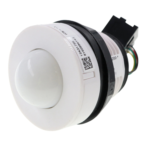
Ceiling mounted infrared multi-sensors offering motion, light, and temperature sensing
The multi-sensor combines the following in a small and discreet
in-ceiling device:
■infrared receiver
■motion sensor
■luminosity level sensor
■temperature sensor
The EC-Multi-Sensor is connected to the ECx Subnetwork via a single
RJ-45 cable. It can be daisy chained using an ECx Subnet Adapter.
Figure 1-1: EC-Multi-Sensor Front
1. Product Description 2. General Installation Requirements
For proper installation and subsequent operation of the sensor, pay
special attention to the following recommendations:
■It is recommended that the sensor be kept at room temperature for
at least 24 hours before installation to allow any condensation that
may have accumulated due to low temperature during shipping/
storage to evaporate.
■Upon unpacking the product, inspect the contents of the carton for
shipping damages. Do not install damaged sensors.
■Avoid areas where corroding, deteriorating or explosive vapors,
fumes or gases may be present.
■Do not install onto a direct sunlight source.
■Do not install close to airow (fan coil unit, ceiling air diffuser, etc.).
■The sensor’s datasheet species the power consumption, the
operating temperature range, and other environmental conditions
the sensor is designed to operate under.
■Do not drop the sensor or subject it to physical shock.
■If the sensor is used and/or installed in a manner not specied by
Distech Controls, the functionality and the protection provided by
the sensor may be impaired..
Take reasonable precautions to prevent electrostatic
discharges to the sensor when installing, servicing or
operating the sensor. Discharge accumulated static
electricity by touching one’s hand to a securely grounded
object before working with the sensor.
Any type of modication to any Distech Controls product
will void the product’s warranty.
Operating handling or servicing this product must be
achieved by a qualied operator. Turn off power before any
kind of servicing.
Certain markings (symbols) can be found on the side of the sensor
and are dened as:
CE marking: conforms with the essential requirements
of the applicable EC directives.
3. Device Markings (Symbols)
Figure 1-2: EC-Multi-Sensor Back
Infrared Receiver
Luminosity Level Sensor
Motion Sensor
EOL Termination Subnet ID Rotary Switch
Rear Spring
Screw Hole
RJ-45 Connector

EC-Multi-Sensor Series
2/6
4. Dimensions 5. Mounting Instructions
The EC-Multi-Sensor can be mounted directly into suspended ceiling
(Ø 32 mm) xed by a supplied rear spring. Please contact us for other
installation procedures.
Suspended Ceiling Installation
1. Drill a Ø 32 mm hole into the suspended ceiling:
Units : mm
Figure 4-1: (From top to bottom) front view and side view of the enclosure
Ø 40 (1.6)
25 (1.0)
3 (0.1)
Ø 32 (1.3)
40 (1.6)
Ø 40 (1.6)
Units: mm (inches)
Ø 40 (1.6)
25 (1.0)
3 (0.1)
Ø 32 (1.3)
40 (1.6)
Ø 40 (1.6)
Units: mm (inches)
Please note that the EOL termination and the Subnet
ID must be set before installing. See Subnetwork Bus
Topology and EOL Terminations and Device Addressing.
2. Introduce the EC-Multi-Sensor through the hole (recessed part
rst):
3. Screw the rear spring to the EC-Multi-Sensor:
4. The EC-Multi-Sensor is now xed into the suspended ceiling:

EC-Multi-Sensor Series 3/6
Figure 6-1: ECx Subnetwork
EC-Multi-Sensors operate off of a separate sub-bus linked to the
RJ-45 Subnet connector of the compatible ECx Subnetwork device
with an RJ45-RJ45 link. The Network Guide provides extensive
informationandrequirementstoimplement this subnetwork.It contains
information about network length, cable type, addressing, etc. It can be
downloaded from the Distech Controls website.
EC-Multi-Sensor can be freely combined (refer to the master controller’s
datasheet for more specication) in a daisy chain conguration, in
which case an optional ECx Subnet Adapter is required to establish a
pass-through connection.
Cable length between each device of the subnetwork (main HVAC
controller / ECx-Light/Blind expansion modules / RJ-45 Accessories)
should not exceed 30 m (100 ft).
The total maximum length of the Subnetwork bus is 180 m (600 ft).
6. Subnetwork Communications Wiring
LON or BACnet Network
Do not crimp one connector as T568A and crimp the
other connector as T568B on the same cable.
Pin T568A (at both cable ends) T568B (at both cable ends)
Pair Color Pair Color
13white/green stripe 2white/orange stripe
23
green solid 2orange solid
32white/orange stripe 3white/green stripe
4 1 blue solid 1blue solid
5 1 white/blue stripe 1white/blue stripe
6 2 orange solid 3green solid
7 4 white/brown stripe 4white/brown stripe
8 4 brown solid 4brown solid
The nal result of a crimped RJ-45 connector is shown graphically
below.
If you make your own patch cable, use Category 5e cable crimped with
RJ-45 connectors either as T568Aor T568B.
Table 6-1: T568A and T568B Terminations for an RJ-45 Connector
Patch cables tted with connectors supplied by Distech Controls are
wired as T568B.
T568A T568B
1 2 3 4 5 6 7 8 1 2 3 4 5 6 7 8
Stripe Solid
Pair3 Pair 1 Pair 2 Pair 4 Pair 2 Pair 1 Pair 3 Pair 4
Key:
Figure 6-2: T568A and T568B Crimp Wire Sequence for an RJ-45 Connector
Figure 6-3: Pins on RJ-45 Jack Face
The last daisy-chained subnetwork device must have its
EOL resistors enabled / installed. All other devices must
have their EOL resistor disabled.
If the EC-Multi-Sensor is not the last device on the ECx
subnetwork, it must be daisy chained using an ECx
Subnet Adapter. To do so, simply clip the ECx Subnet
Adapter male connector into the EC-Multi-Sensor,
and connect the next and previous devices to the
ECx-Subnet Adapter female connectors, one in each
plug.

EC-Multi-Sensor Series
4/6
7. SubnetworkBusTopologyandEOLTerminations
When ECx subnetwork devices are installed with a PTU Series or VAV
controller, only the last device (expansion module or room device)
EOL termination is set to ON. All other devices must have their EOL
terminations set to OFF.
The EC-Multi-Sensor’s EOL termination is dened by the absence or
the presence of the EOL jumper:
■Absence of EOL jumper: EOL termination OFF
■Presence of EOL jumper: EOL termination ON
Figure 7-1: EOL termination ON
Figure 7-2: EOL termination OFF
8. Device Addressing
Each EC-Multi-Sensor on the ECx Subnetwork must be set to a unique
subnet ID address. The address is set either with the rotary switch
located at the rear of the sensor using a small screwdriver (≤ 2.5 mm -
0.1’’) or with an EC-Remote-I.
■The Subnet ID address must be set before installing
the sensor, as the rotary switch might not be
retrievable once the rear spring installed.
■4 different Subnet ID codications are used on the
ECx Subnetwork :
– 1 for Allure EC-Smart-Vue sensors
– 1 for Allure EC-Smart-Comfort and Allure
EC-Smart-Air sensors
– 1 for EC-Multi-Sensors
– 1 for ECx-Light/Blind expansion modules
Consequently, for example, the same Subnet ID can
be assigned to an ECx-Light/Blind module, to an
EC-Multi-Sensor and to an Allure EC-Smart-Vue sensor
without any adressing issue.
Figure 8-2: Setting the EC-Multi-Sensor Subnet ID Address
Automatic addressing shall only be used if only one
EC-Multi-Sensor is connected to the ECx Subnetwork.
Figure 8-1: EC-Multi-Sensor Rotary switch
Setting the Subnet ID with the rotary switch
Set the desired Subnet ID by pointing the matching number with the
rotary switch arrow
When setting the Subnet ID using the EC-Remote-I, the
rotary switch must be set to 0 (default).
Setting the Subnet ID with the EC-Remote-I
1. Press simultaneously on the remote
control for 3 seconds: the remote control displays MAC for
1 second, followed by the current Subnet ID (default: 1).
2. Set the Subnet ID with and .
3. Press to validate.
If neither nor is pressed for 5 seconds, the
Subnet ID menu is escaped and the Subnet ID is not
modied.
The Subnet IDs that can be allocated to EC-Multi-Sensors are 0
(factory default), 1, 2, 3, and 4. All other adresses are not used.

EC-Multi-Sensor Series 5/6
As the measured temperature is at ceiling height, it must be necessary
to apply an offset to this measure to represent the room temperature
at standard level. Please refer to EC-gfxProgram User Guide for more
information.
Temperature sensing
9. Settings
The Waste Electrical and Electronic Equipment (WEEE) Directive
sets out regulations for the recycling and disposal of products. The
WEEE2002/96/EG Directive applies to standalone products, for
example, products that can function entirely on their own and are not a
part of another system or piece of equipment.
For this reason Distech Controls products are exempt from the WEEE
Directive. Nevertheless, Distech Controls products are marked with
the WEEE symbol , indicating devices are not to be thrown away
in municipal waste.
Products must be disposed of at the end of their useful life according
to local regulations and the WEEE Directive.
10. Disposal
Changes or modications not expressly approved by
Distech Controls could void the user’s authority to operate
the equipment.
This equipment has been tested and found to comply
with the limits for a Class B digital device, pursuant to
Part 15 of the FCC Rules. These limits are designed
to provide reasonable protection against harmful
interference in a residential installation. This equipment
generates, uses and can radiate radio frequency energy
and, if not installed and used in accordance with the
instructions, may cause harmful interference to radio
communications. However, there is no guarantee that
interference will not occur in a particular installation. If
this equipment does cause harmful interference to radio
or television reception, which can be determined by
turning the equipment off and on, the user is encouraged
to try to correct the interference by one or more of the
following measures:
• Reorient or relocate the receiving antenna.
• Increase the separation between the equipment and
receiver.
• Connect the equipment into an outlet on a circuit
different from that to which the receiver is connected.
• Consult the dealer or an experienced radio/TV
technician for help.
The infrared receiver can be used to associate the EC-Multi-Sensor
to an EC-Remote-I. The matching sight range can be viewed in the
EC-Multi-Sensor datasheet. The default infrared zone number is 0.
This parameter can be modied using EC-gfxProgram. Please refer to
EC-gfxProgram User Guide for more information.
Infrared reception
11. FCC Statement
As the luminosity level in a room is not homogeneous but depends
on the measurement position and on the room layout (colors, desk
position, light sources...), the luminosity level acquired by the
EC-Multi-Sensor might not be the luminosity level at the workplace.
To precisely measure the luminosity level at the desired position, a
calibration must be achieved.
■Please note that the luminosity level calibration must
be achieved at the approximate desired luminosity
level.
1. Position the luxmeter at the exact position the user operates
(typically on a desk).
2. Note the luminosity level value.
3. Luminosity level calibration can then be achieved by entering this
value using the dedicated EC-gfxProgram custom block.
Luminosity level measurement calibration
To achieve luminosity level measurement calibration:
Motion sensitivity can be adjusted in EC-gfxProgram so as to avoid
unwanted interferences while ensuring actual movements remain
detected. Please refer to EC-gfxProgram User Guide for more
information.
Motion sensitivity

05DI-HIECMSX-12
05DI-HIECMSX-12
EC-Multi-Sensor Series
6/6
©, Distech Controls Inc., 2013. All rights reserved.
While all efforts have been made to verify the accuracy of information in this manual, Distech Controls is not responsible for damages or claims arising from the
use of this manual. Persons using this manual are assumed to be trained specialist / installers and are responsible for using the correct wiring procedures and
maintaining safe working conditions with fail-safe environments. Distech Controls reserves the right to change, delete or add to the information in this manual at any
time without notice.
Distech Controls, the Distech Controls logo, Innovative Solutions for Greener Buildings, and Allure are trademarks of Distech Controls Inc. All other trademarks are
property of their respective owners.
Total Quality Commitment
AllDistechControlsproduct lines arebuilttomeet rigorous qualitystandards.DistechControls isanISO9001 registered company.
Table of contents
Other Distech Controls Accessories manuals

Distech Controls
Distech Controls UNIWAVE User manual

Distech Controls
Distech Controls Allure EC-Smart-Vue Series User manual

Distech Controls
Distech Controls GS-AQR Manual

Distech Controls
Distech Controls Allure EC-Sensor Series Manual

Distech Controls
Distech Controls EC-Multi-Sensor-BLE User manual

Distech Controls
Distech Controls HS-THX User manual

Distech Controls
Distech Controls Allure UNITOUCH Manual

Distech Controls
Distech Controls Allure EC-Smart-Air Series User manual