FT FT742 User manual

1 FT742-DM (RS485) Sensors –User Manual
FT TECHNOLOGIES LTD.
SUNBURY HOUSE
BROOKLANDS CLOSE
SUNBURY-ON-THAMES
MIDDLESEX TW16 7DX
TEL: +44 (0)20 8943 0801
FAX: +44 (0)20 8943 3283
WEB: www.fttechnologies.com
E-MAIL: info@fttechnologies.com
A4278-3-EN
October 2017
The FT and Acu-Res logos are registered trademarks of FT Technologies Ltd.
Copyright © 2017 FT Technologies Ltd. All rights reserved.
FT742 –Digital (RS485) Wind Sensor Manual
Direct-Mount Variant

2 FT742-DM (RS485) Sensors –User Manual
Contents
Product Symbols......................................................................................................4
Safety Instructions...................................................................................................5
Consignes de sécurité.............................................................................................6
1INTRODUCTION................................................................................................. 7
1.1 Product Overview ................................................................................................................7
1.2 Build Versions and Labelling .............................................................................................7
1.3 Scope of Use........................................................................................................................7
1.4 Disclaimer.............................................................................................................................8
2FUNCTIONAL DESCRIPTION ...........................................................................9
2.1 Technical Performance .......................................................................................................9
2.2 Wind Speed Calibration ....................................................................................................10
2.3 Wind Speed and Direction Filtering.................................................................................10
2.4 Electronic Rotation of the Datum Direction....................................................................11
2.5 Selective Filter Scheme.....................................................................................................11
2.6 Error Detection...................................................................................................................11
2.7 Overspeed Warning Scheme............................................................................................11
2.8 Heater Setup.......................................................................................................................11
2.9 Low Power Operation........................................................................................................12
3MECHANICAL & ELECTRICAL INSTALLATION............................................13
3.1 Connector Details..............................................................................................................20
3.2 Cable Details ......................................................................................................................20
3.3 Lightning, Surge & EMI protection ..................................................................................21
4SERVICE, CONFIGURATION & TESTING......................................................23
4.1 Inspection...........................................................................................................................23
4.2 Fault Finding & Troubleshooting.....................................................................................24
4.3 Returns ...............................................................................................................................25
4.4 The Acu-Test Pack.............................................................................................................26
4.4.1 The Acu Vis PC Software................................................................................................26
4.4.2 FT054 Evaluation Cable..................................................................................................27
5SENSOR COMMUNICATION...........................................................................29
5.1 Introduction........................................................................................................................29
5.2 RS485 Protocol ..................................................................................................................29
5.3 Configuring the Sensor.....................................................................................................30
5.4 Communication..................................................................................................................30
5.4.1 Conventions used in this manual ....................................................................................30
5.4.2 Data Transmission ..........................................................................................................31

3 FT742-DM (RS485) Sensors –User Manual
5.4.3 Message Format..............................................................................................................31
5.4.4 Listener and Talker Identifiers.........................................................................................32
5.4.5 Calculating the Message Checksum...............................................................................32
5.4.6 Disabling the Checksum..................................................................................................32
6PARAMETER SETTINGS ................................................................................34
6.1 Command Types................................................................................................................34
6.1.1 Set Commands................................................................................................................34
6.1.2 Query Commands ...........................................................................................................35
6.2 User Calibration Table.......................................................................................................36
6.3 Timing Constraints............................................................................................................37
6.4 Command Parameters.......................................................................................................38
6.4.1 BR: Set or Query the Serial Interface Baud Rate............................................................38
6.4.2 CF: Set or Query the Wind Datum Offset Angle .............................................................39
6.4.3 CU: Set or Query the Continuous Update Setting...........................................................40
6.4.4 DF: Set or Query the Wind Velocity Data Format ...........................................................41
6.4.5 DG: Query the Run-time Counter....................................................................................42
6.4.6 DL: Set or Query the Command Delay Interval...............................................................43
6.4.7 ER: Query or Reset the Error Report..............................................................................44
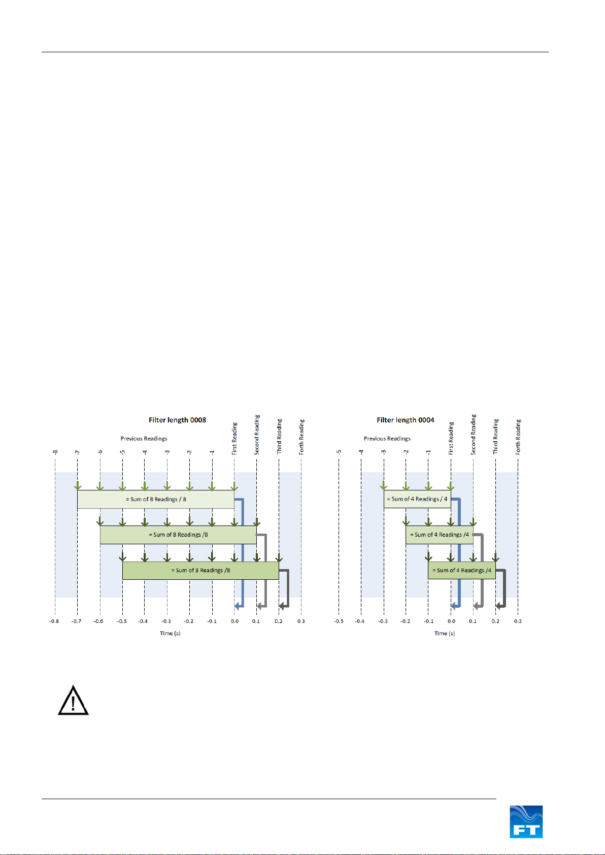
6.4.8 FL.1: General Filter Settings ...........................................................................................45
6.4.9 FL.2: Set or Query Filter Lengths....................................................................................46
6.4.10 FL.3: Set or Query the Selective Filter........................................................................47
6.4.11 HT.1: General Heater Settings...................................................................................48
6.4.12 HT.2: Delay Heater Settings ......................................................................................49
6.4.13 HT.3: Limit Heater Settings.........................................................................................50
6.4.14 ID: Set or Query the Listener & Talker Identifiers.......................................................51
6.4.15 MM: Reset or Query the Min/Max Recorded Wind Speed..........................................52
6.4.16 OS: Overspeed Warning Scheme..............................................................................53
6.4.17 PR: Query the Parameter Report................................................................................54
6.4.18 RS: Reset the Sensor .................................................................................................55
6.4.19 SN: Query the Serial Number and Platform Version ..................................................56
6.4.20 SV: Query the Software Version.................................................................................57
6.4.21 UC.1: General User Calibration Settings....................................................................58
6.4.22 UC.2: Clear User Calibration Table Record................................................................59
6.4.23 UC.3: Set User Calibration Table Record...................................................................60
6.4.24 UC.4: Save and Read User Calibration Table............................................................61
6.4.25 UC.5: Set & Query User Calibration Table Label .......................................................62
6.4.26 US: Set or Query Saved Parameters..........................................................................63
6.4.27 WV Polar: Query the Wind Velocity Reading..............................................................65
6.4.28 WV NMEA: Query the Wind Velocity Reading............................................................66

4 FT742-DM (RS485) Sensors –User Manual
Product Symbols
The following symbols may be used upon the product and within the manual.
Meaning / Description
Symbol
Signification / Description
Warning/ Caution
An appropriate safety instruction should be
followed or caution to a potential hazard
exists
Avertissement / Attention
Une instruction de sécurité doit être
suivie ou attention portée à un
danger potentiel qui existe.
DC Current only
Equipment operates under Direct Current
(DC) supply only.
Courant continu uniquement
L'équipement fonctionne sous une
alimentation en courant continu (CC)
uniquement.
Product Disposal
In accordance with European directive
2012/19/EU on Waste Electrical and
Electronic Equipment (WEEE), these
product components must be recycled. This
should be done by returning the product to
FT Technologies or by using an appropriate
waste disposal company. This product
should not be disposed of in general waste
of landfill. This product complies with the
RoHS2 (2011/65/EU) directive.
Élimination du produit
Conformément à la directive
européenne 2012/19/EU relative aux
déchets d'équipements électriques et
électroniques (DEEE), ces
composants du produit doivent être
recyclés. Cela doit être fait par le
retour du produit à FT Technologies
ou en utilisant une entreprise
d'élimination de déchets. Ce produit
ne doit pas être éliminé avec les
ordures ménagères ou en décharge.
Ce produit conforme à la RoHS2
(2011/65/EU).
Recognized Component
Sensors marked with the ETL label indicate
that the product conforms to UL Standard
61010-1 and is certified to CSA Standard
C22.2 No. 61010-1.
4000105
Composant Reconnu
Les capteurs marqués avec
l’étiquette ETL indiquent que le
produit est conforme à la norme UL
61010-01 et est certifié à la norme
CSA22.2 61010-01.
CE Mark
The EU Declaration of Conformity
complies with the essential requirements
of the following applicable EMC Directive
2014/30/EU, and carries the CE Marking
accordingly.
Marquage CE
Déclaration de conformité CE de la
compatibilité électromagnétique
(EMC) et marquage CE
conformément à la directive CE
2014/30/EU.

5 FT742-DM (RS485) Sensors –User Manual
Safety Instructions
English
•To ensure the safe installation and operation of this product the equipment must be installed and
integrated:
oUsing suitably qualified and trained personnel
oIn accordance with any regional electrical codes
oIn accordance with the instructions set out in this manual, observing all information, warnings
and instructions
oIn accordance with any other instructions or guidance FT Technologies provide
•To ensure that the product remains compliant with the electrical safety requirements of the UL / CSA
61010-1 Standards it must be;
oConnected to an appropriately approved isolated power supply (for example UL/CSA IEC
60950-1:2005 + A1:2009 + A2:2013) rated 12-30VDC and be current limited (6A Max)
oProtected by UL 1449 listed surge protection devices
oConnected with an approved interface cable (for example UL/ CSA recognised AWM style
21198, rated 300V, 80°C)
•The equipment must only be operated within the range of the specified technical data and used for the
purposes for which it was designed.
•The equipment should always be transported in packaging which is appropriate, that will prevent any
accidental damage from occurring.
•Always ensure that any failures or errors from the product cannot cause any damage to any other
equipment or property or cause any other consequential effects.

6 FT742-DM (RS485) Sensors –User Manual
Consignes de sécurité
Français
•Pour assurer la sécurité de l'installation et le fonctionnement de ce produit, l'équipement doit être
installé et intégré :
oÀ l'aide de personnel qualifié et formé
oConformément à tous les codes électriques régionaux
oConformément aux instructions figurant dans ce manuel et en observant toutes les
informations, avertissements et instructions
oConformément à d'autres instructions ou directives que FT Technologies fournit
•Pour garantir que le produit reste compatible avec les exigences de sécurité électrique de l'UL/CSA
61010-1 normes, l'équipement doit être :
oConnecté à une alimentation agrée convenablement isolée (par exemple UL/CSA IEC 60950-
1:2005 + A1:2009 + A2:2013) de tension nominale 12-30 VCC et avec courant limité (6 A max)
oProtégé par des dispositifs de protection UL 1449 contre les surtensions
oConnecté avec un câble d'interface (par exemple UL/CSA reconnu AWM style 21198, de
valeur nominale 300 V, 80°C)
•L'équipement doit être utilisé uniquement dans la plage des données techniques spécifiées et utilisé
aux fins pour lesquelles il a été conçu.
•L'équipement doit toujours être transporté dans un emballage qui est approprié, qui permettra d'éviter
qu'un quelconque dommage accidentel ne survienne.
•En toutes circonstances, garantir que les défaillances ou les erreurs du produit ne puissent pas causer
des dommages à d'autres équipements ou autres biens ou provoquer d'autres effets indirects.

Section 1 Introduction
7 FT742-DM (RS485) Sensors –User Manual
1 INTRODUCTION
1.1 Product Overview
The FT742-D-DM sensor is designed for general meteorological applications - particularly in harsh
environments such as areas of icing, sand, dust and offshore installation. The solid-state ultrasonic
wind sensor uses acoustic resonance airflow sensing techniques to measure both wind speed and
direction. The wind sensor has no moving parts to degrade or wear-out and is designed for
applications requiring high reliability.
Mounting and aligning the sensor is simple. A compass (not supplied) can be used to align the sensor
with magnetic North (0°) using the 0° wind datum marking feature (see Figure 3). For operation in ice-
prone areas, the FT742 is fitted with a highly-effective thermostatically controlled all-body heating
system. A three-element heater is used to ensure heat is evenly distributed over the entire surface
area.
FT sensors are configurable and can be factory programmed to the required customer settings,
contact FT Technologies for further details.
Note: The FT742-DM range is not suitable for turbine control applications. The FT742-FF and FT742-
PM ranges are designed for this application.
The standard FT742-DM, when installed to FT Technologies recommendations, is electrically isolated
from the mounting pole, making it unsuitable for conductively-grounded lightning protection schemes.
The addition of the FT035 grounding accessory provides a reliable, low-resistance grounding path.
Refer to Section 3 or contact FT Technologies for further information.
1.2 Build Versions and Labelling
Figure 1 shows how to identify a sensor, the serial number and calibration code (if applicable):
Additional labels may be attached. Only sensors marked with the Intertek label conform to the UL
Standard 61010-1 and are certified to CSA Standard C22.2 No. 61010-1.
Figure 1: Examples of Main Sensor Labels
1.3 Scope of Use
The sensor is designed, manufactured and optimised for high availability.
No promise in part or full can be given to guarantee a sensor’s continuous operation, as exceptional
circumstances can occur that may result in the failure of the output from a sensor. Exceptional
circumstances can include:
•Poor installation
•Inadequate inspection
•Power supply failures
•Poor quality electrical connections
•Lightning exposure
•Problematic environmental conditions or combination of conditions
•Physical Damage

Section 1 Introduction
8 FT742-DM (RS485) Sensors –User Manual
1.4 Disclaimer
There are no warranties, representations or conditions, expressed or implied of any kind given in this
manual for any particular design application. The Purchaser should independently undertake sufficient
testing to confirm validity and suitability of any design. The Purchaser assumes all risks and liability in
conjunction with the use of the information given.
Any warranty given by FT Technologies in respect of the equipment is conditional upon the sensor
being handled, installed, integrated and operated in accordance within the guidelines given in this
manual.
FT Technologies can take no responsibility for the effectiveness of any sensor lightning protection
scheme implemented.
Information supplied by FT Technologies Ltd. shall not be construed as permission to license to operate
under, or recommendation to infringe any existing or pending patent, patent applications or trademarks.

Section 2 Functional Description
9 FT742-DM (RS485) Sensors –User Manual
2 FUNCTIONAL DESCRIPTION
2.1 Technical Performance
Sensor Performance1 & 2
Measurement Principle Acoustic Resonance (compensated against variations in temperature,
pressure and humidity)
Wind speed Measurement
Range 0-75m/s
Resolution 0.1m/s
Accuracy ±0.3m/s (0-16m/s)
±2% (16m/s-40m/s)
±4% (40m/s-75m/s)
Knots and km/h options available.
Wind Direction Measurement
Range 0 to 360°
Accuracy 4° RMS
Resolution 1
Environment
Temperature Range -40 to +85C (operating and storage)
Humidity 0-100%
Altitude 0-4000m
Data I/O
RS485 Interface Digital RS485, galvanically isolated from power supply lines and
case
Format ASCII data, polled or continuous output modes
Data Update Rate Up to 10 measurements per second (10Hz)
Power Requirements3
Supply Voltage 24VDC nominal (12-30VDC range)
Supply Current (Heater off) 31mA (typical)
Supply Current (Heater on) 6A (max 5) –The heater is thermostatically controlled. Heater power
consumption will depend on the heater energy required to keep the sensor’s
temperature at a user determined set point. The sensor is limited to 4A and
99W 4 by the default software settings (the heater current and voltage limits
can be modified, see Sections 6.4.11 & 6.4.13 for further details or contact
FT Technologies).
Physical
Weight 380g (without size adaptors)
Material Aluminium alloy (hard anodised)
I/O Connector 5 way (RS485 option)
Mounting Method Pipe-Mount screw fix (33.7mm external diameter EN10255 pipe).
Various size adaptors and pipe-inserts available.
Notes:
1.All specifications subject to change without notice.
2.Specifications calculated with the default settings and filters enabled.
3.See safety instruction requirements (page 5 and 6).
4.The heater set point, current limit and maximum power limits can be pre-configured in the factory or
adjusted using the FT Acu-Test Digital kit.

Section 2 Functional Description
10 FT742-DM (RS485) Sensors –User Manual
2.2 Wind Speed Calibration
All FT742-DM wind sensors get calibrated in the FT production wind tunnel before dispatch. As the sensor has
no moving parts, there is no need to recalibrate a sensor over its lifetime as no measurement degradation will
occur. The sensor’s compact strong monolithic shape is designed to prevent accidental transducer movement
or damage. FT Technologies’calibration procedure and wind tunnels are designed to give a calibration profile
that is within the accuracy limits set in the product technical specification (see Section 2.1). Periodically the
accuracy of FT’s wind tunnels are compared with the accuracy of an independent wind tunnel to ensure that no
drift has occurred.
In exceptional circumstances users may wish to apply additional calibration factors. The sensor has an option to
set a User Calibration Table, which can modify the wind sensor’s wind speed output (see Section 6.4.21).
The User Calibration Table can be programmed with up to 64 correction factors which are maintained in non-
volatile memory. When enabled, the uncorrected wind speed output is adjusted according to the stored User
Calibration Table records using linear interpolation. The adjustments are applied to wind speed readings
regardless of wind direction.
2.3 Wind Speed and Direction Filtering
It is important that the system does not rely exclusively on a single wind reading for any control decision. A
single reading may be inaccurate due to measurement error, turbulence, corruption or interference. It is
recommended that an average of wind readings is used. In addition if 100% data availability is required then a
second FT sensor or alternative wind sensors should be fitted in addition.
The sensor has optional internal filtering available. This is a digital finite impulse response (FIR) filter, which
works by calculating the moving average of a fixed number of previous readings. If filtering is being applied
externally, the sensor’s output filters can be disabled. If filtering inside the sensor is preferred, the length of the
averaging for both wind speed and direction can be independently set (see Sections 6.4.8 and 6.4.9).
Figure 2: Examples of FIR Filtering
It is recommended to use average readings to reduce the effects of air turbulence.

Section 2 Functional Description
11 FT742-DM (RS485) Sensors –User Manual
2.4 Electronic Rotation of the Datum Direction
The datum direction of the sensor can be offset electronically by using the CF command (Section 6.4.2). This
facility can be used to adjust the datum direction in case of any mechanical misalignment within the mounting
arrangement. To offset the datum direction, in either the clockwise or anticlockwise direction, use the CF
command (Section 6.4.2). Once the offset has been set it will be retained in the sensor Flash memory.
2.5 Selective Filter Scheme
In addition to the averaging filter described in Section 2.3, the sensor has a feature called the Selective Filter.
The scheme allows the user to set a “validity period”, during which the sensor will exclude invalid readings from
entering the averaging filter (see Section 6.4.8). The output will freeze on the last previous “good” reading and
only raise an error flag once the number of bad readings exceeds the validity period. This scheme can be
enabled by factory configuration or using the FL command (see Section 6.4.10). The filter is turned off by default
to match legacy behaviour.
2.6 Error Detection
The sensor has a self-checking mechanism which can detect if a reading is invalid. On very rare occasions
where an invalid reading may have been detected, this is signalled to the computer or data logger by setting an
error flag character within the wind velocity output message (see Sections 6.4.27 and 6.4.28).
When an error is detected, the error flag character is set to a value of: 1.
Note: An optional Overspeed Warning Scheme can be enabled (but is disabled by default). See Section 6.4.16
for further details.
It is important that error flags are not ignored. Data associated with an error flag should not be processed as
valid wind data. The system should be capable of riding through rare periods when data may be temporarily
unavailable. If errors are ongoing (more than several seconds), a reset of the sensor should be applied (see
Section 6.4.18 for instructions on sending an RSU command).
It is recommended that errors are monitored and logged. If the frequency of errors has recently increased, then
inspection of the sensor for physical blockages may be required (see Section 4.1).
2.7 Overspeed Warning Scheme
During periods where the sensor detects wind speed beyond the rating of the sensor, the sensor will (by default)
indicate a general error flag status.
An additional overspeed warning scheme can be enabled where in the event of wind speeds beyond the rating
of the sensor, the error flag character will be set to 2 (see Sections 6.4.27 and 6.4.28) unless a general error
condition is also detected and the flag will be set to 1.
To comply with legacy behaviour, this scheme is disabled by default.
The Overspeed Warning Scheme can be enabled by software commands (see Section 6.4.16), using the
Acu-Test Digital kit (see Section 4.4) or enabled in the factory before despatch.
2.8 Heater Setup
The sensor is fitted with an integral three-element distributed heater that can be used to prevent icing-up of the
sensor in freezing temperatures. The heater is controlled automatically by the sensor using a user
programmable ‘set point’ temperature. The sensor uses a control scheme which dynamically changes the
current supplied to each individual heater element in order to maintain the programmed set point temperature.
We recommend selecting a suitable set-point temperature for the sensor environment. Factors to consider
include ambient temperature, relative humidity, wind speed and ice/snow conditions. This setting can be
programmed by the factory, by using the Acu Vis Test software (see Section 4.4) or the heater software
commands (see Section 6.4.11).

Section 2 Functional Description
12 FT742-DM (RS485) Sensors –User Manual
It is important to consider cable resistance losses and use a suitably rated cable of an appropriate length. FT
recommends cable types in Section 3.2 and the cable length should not exceed 15m. If longer cables runs are
required, consider the use of a junction box and heavy-gauge cable.
Since the heater circuit is thermostatically controlled, the actual power being drawn from the supply will depend
on the programmed set-point and the environmental conditions (i.e. ambient temperature, wind speed,
precipitation etc.). The maximum power that the sensor can consume is by default limited to 99W (4A with the
heater enabled). The power supply must be rated to provide the maximum power that the sensor can consume.
The maximum current limit of the sensor can be adjusted in software from 0.1 –6A (from the default of 4A and
in increments of 0.1A). The current limit can be programmed at the factory, modified using the Acu-Test PC
software (see Section 4.4), or by using the software command (see Section 6.4.13). By default, the heater
requires a minimum of 11VDC for operation, see Section 6.4.13 for further details.
2.9 Low Power Operation
The sensor is designed for typical operation at 24VDC, however the sensor can operate below this (12-30VDC)
with reduced performance. By default, the heater will shut down at approximately 11VDC. Below approximately
8V the sensor may shut down. Lower voltages reduce the overall power consumption and heater performance.
For further advice on power and heater management strategies, see Sections 6.4.11, 6.4.12 and 6.4.13, or
contact FT Technologies.

Section 3 Mechanical & Electrical Installation
13 FT742-DM (RS485) Sensors –User Manual
3 MECHANICAL & ELECTRICAL INSTALLATION
The wind sensor has no moving parts to degrade or wear-out and is designed for applications requiring high
reliability and cold weather operation.
Figure 3: The Direct Mount Sensor
Direct Mount sensors are mounted vertically with the cable connector routed down through a 33.7mm (outer
diameter) hollow pipe (EN10255 standard sizes). 4 M6 screws can be used to secure the sensor onto the pipe
(Figure 7). The sensor body is manufactured from hard-anodised aluminium and the cavity has a water-repellent
coating.
A suitable compass (not supplied) can be used to align the sensor with magnetic North using the convenient ‘N’
alignment marking and the alignment flat. The magnetic North marking indicates 0° and rotates clockwise when
viewed from above (see Figure 6). The alignment flat is used with a square-sided compass for rotational
alignment. Magnetic North should be lined up to face parallel to the ‘N’ marking feature.
Ensure the airflow into the sensor is not obstructed or influenced by nearby objects.
In order to keep the pressure within the sensor equalised with the atmospheric pressure, a small breather hole
is located within the connector housing compartment that should not be blocked.
•See safety instruction requirements on pages 5 and 6.
•The wind sensor installation must be properly designed to ensure the correct
operation of the sensor. This section is for guidance only. It is the responsibility of
the designer and installer to ensure that the installation and its design is fit for
purpose. Please see Disclaimer Section 1.4.

Section 3 Mechanical & Electrical Installation
14 FT742-DM (RS485) Sensors –User Manual
The mounting pipe should have a minimum galvanising thickness of 50μm to ensure long-term protection
against corrosion (a relevant galvanising design standard should be considered, for example ASTM A123 or
ISO 1461-2009). Aluminium components of the appropriate grade could be used as an alternative.
At the base of the sensor the mounting pipe meets the sensor (visible when viewed from below). The contact
surface ring (see Figure 4) at the top is hard-anodised and unsuitable for electrical grounding between the
sensor body and ground. This connection should be checked as part of the annual inspection of the sensor (see
Section 4.2). The FT035 grounding accessory can be fitted within the connector chamber and can provide a
low-resistance grounding path to the outer edge of the mounting pipe. The FT035 is comprised of a coiled
metallic spring fitted within the circular inner wall, mating with the outer edge of the mounting pipe, it can be
viewed from the below viewpoint:
Figure 4: Direct-Mount –Connector (View From Below and FT035 Location)
The following replacement parts are available:
FT027
O-ring (3.53 CS x 32.92 ID)
FT031
Size Adaptor 25mm (1”) for FT742-DM (includes a FT033 tapered pipe insert & 4x FT034
self-locking fasteners)
FT032
Size Adaptor 50mm (2”) for FT742-DM (includes a FT033 tapered pipe insert & 4x FT034
self-locking fasteners)
FT033
Tapered Pipe Insert (33.7mm OD)
FT034
1x Self-locking Fastener
FT035
Grounding Accessory

Section 3 Mechanical & Electrical Installation
15 FT742-DM (RS485) Sensors –User Manual

Section 3 Mechanical & Electrical Installation
16 FT742-DM (RS485) Sensors –User Manual
Figure 5: Direct Mount Sensor (mm)

Section 3 Mechanical & Electrical Installation
17 FT742-DM (RS485) Sensors –User Manual
The sensor measures the wind direction relative to the alignment flat and the central datum feature. When the
wind sensor is correctly aligned the wind direction measurements will be as shown in Figure 6.
Figure 6: Wind Direction (view from above)

Section 3 Mechanical & Electrical Installation
18 FT742-DM (RS485) Sensors –User Manual
1. Push the slotted end of the pipe insert into the mounting pipe.
Apply a continuous seam of all-weather adhesive sealant
around each of the two channels, before pushing the insert fully
into the pipe, ensuring the shoulder is flat and any surplus
sealant is wiped away. This insert provides a smooth transition
for the sensor O ring to facilitate easy mounting of the DM with
no damage to the internal O ring (for alternative pipe sizes use
the available size adaptors)
2. Pass the cable through the mounting pipe and pipe insert
3. Connect the cable to the wind sensor and lower the DM base
onto the pipe
4. Rotate the sensor to align the central North (‘N’ datum, feature)
with magnetic North (or an alternative reference)
5. Tighten four self-locking fasteners (4x part FT034) ensuring an
even distribution of pressure and firm contact with the mounting
pipe. The fixings use a thread-locking insert and will provide
resistance before they are fully engaged. In highly corrosive
environments (such as coastal installations) the use of marine
grade self-adhesive tape (such as USCGFP by 3M) is
recommended to apply over the top of the mounting fasteners
to ensure ease of removal. In these environments, it is also
beneficial to apply sealant around the base of the sensor at the
pipe interface to reduce build-up of corrosion that could make
sensor removal difficult.
Confirm the installation is safe and appropriate for the
environment.
FT provides optional size adaptors to suit mounting diameters of
25mm (FT031) and 50mm (FT032). Ensure the internal diameter
allows the interface cable to pass through.
Pipe Insert (FT033)
25mm size adaptor (FT031)
50mm size adaptor (FT032)
Figure 7: Direct-Mount Sensor Pipe Installation –Including tapered pipe insert and size adaptors

Section 3 Mechanical & Electrical Installation
19 FT742-DM (RS485) Sensors –User Manual
Figure 8: Direct-Mount Compass Alignment

Section 3 Mechanical & Electrical Installation
20 FT742-DM (RS485) Sensors –User Manual
3.1 Connector Details
All electrical connections are made to the sensor via a 5-way multipole connector located in the base of the wind
sensor housing. The connector pin designations are shown in Figure 9 and the connector/mating connector
manufacturer’s part numbers in Figure 10.
Figure 9: Sensor Connector Pins
Manufacturer
Connector Type
Connector
Description
Manufacturers Part
Number
Maximum Outer
Cable Diameter
W.W.Fischer
Cable Side
Connector
5 way plug
SE104Z053-130/8.7
8.0mm
ODU
Cable Side
Connector
5 way plug
SX2F1C-P05NJH9-0001
9.2mm
Figure 10: Connector Sourcing Options
3.2 Cable Details
The mating connectors for the sensor are suitable for use with cables with overall diameters as described in the
table above and for individual cores of diameters of up to 1.2mm. Cable such as SD980CPTP 3x2x0.5mm² from
SAB Brockskes or similar types may be used. Care must be taken to ensure that the cable is suitable for the
environment it will be used in and is adequately approved, for example AWM Style 21198.
In an area with a moderate or severe lightning strike exposure the cable shield may not provide sufficient
protection. In this case the cable will require further shielding such as being enclosed in a metal pipe or conduit.
This manual suits for next models
1
Table of contents
Popular Accessories manuals by other brands

Optima Scale
Optima Scale OP-905 user manual

Deantron
Deantron iNod Series instructions

Lambrecht
Lambrecht PROFESSIONAL-IX 3.0 operating instructions

Parlex
Parlex iMist user manual

PCB Piezotronics
PCB Piezotronics 208M133 Installation and operating manual

Sper scientific
Sper scientific 330001 instruction manual

Chamberlain
Chamberlain DH Wiring diagram

iOptron
iOptron HAE29 quick start guide

Shure
Shure SEK-2 instruction manual

Dräger
Dräger Incubator 8000 IC Instructions for use

Clas Ohlson
Clas Ohlson WA PUSH WHITE manual

S+S Regeltechnik
S+S Regeltechnik HYGRASGARD KFF Operating Instructions, Mounting & Installation