SICK WLG16 Bluetooth User manual

OPERATING INSTRUCTIONS
WLG16 Bluetooth®

OPERATING INSTRUCTIONS
WLG16 Bluetooth®
de
en

Described product
WLG16 - Bluetooth®
Manufacturer
SICK AG
Erwin-Sick-Str. 1
79183 Waldkirch
Germany
Legal information
This work is protected by copyright. Any rights derived from the copyright shall be
reserved for SICK AG. Reproduction of this document or parts of this document is only
permissible within the limits of the legal determination of Copyright Law. Any modifica‐
tion, abridgment or translation of this document is prohibited without the express writ‐
ten permission of SICK AG.
The trademarks stated in this document are the property of their respective owner.
© SICK AG. All rights reserved.
Original document
This document is an original document of SICK AG.
28022197 | SICK
Subject to change without notice

Contents
1 Safety information............................................................................ 4
1.1 General safety notes................................................................................ 4
1.2 Notes on UL approval............................................................................... 4
2 Intended use...................................................................................... 4
3 Operating and status indicators...................................................... 4
4 Mounting............................................................................................. 5
5 Electrical installation........................................................................ 5
6 Commissioning.................................................................................. 8
7 Troubleshooting................................................................................. 12
8 Disassembly and disposal............................................................... 12
9 Maintenance...................................................................................... 12
10 Approvals............................................................................................ 13
10.1 Bluetooth® approvals............................................................................... 13
11 Technical data.................................................................................... 13
11.1 General technical data............................................................................. 13
11.2 Bluetooth technical data®....................................................................... 14
CONTENTS
8022197 | SICK
Subject to change without notice 3

1 Safety information
1.1 General safety notes
■Read the operating instructions before commissioning.
■
Connection, mounting, and setting may only be performed by trained spe‐
cialists.
■Not a safety component in accordance with the EU Machinery Directive.
■When commissioning, protect the device from moisture and contamination.
■These operating instructions contain information required during the life cycle of
the sensor.
1.2 Notes on UL approval
The device must be supplied by a limited voltage / limited current circuit or is intended
to be connected to a Class 2 source of supply. In case of a limited voltage / limited cur‐
rent circuit the device shall be supplied from an isolating transformer having a sec‐
ondary overcurrent protective device that complies with UL 248 to be installed in the
field rated either:
a) max 5 amps for voltages 0~20 V (0~28.3 V peak), or
b) 100/Vp for voltages of 20~30 V (28.3~42.4 V peak).
UL Environmental Rating: Enclosure type 1
2 Intended use
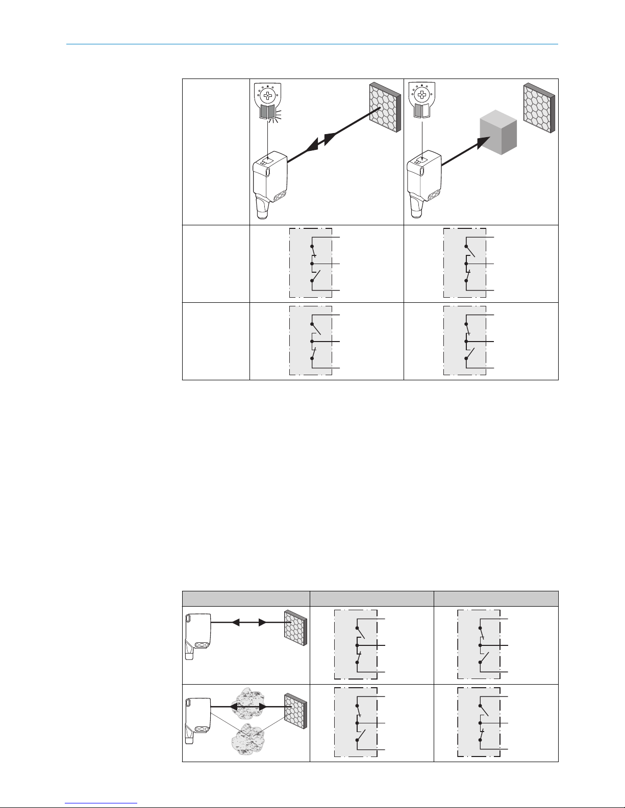
The WLG16 is an opto-electronic photoelectric retro-reflective sensor (referred to as
“sensor” in the following) for the optical, non-contact detection of objects, animals, and
persons. A reflector is required for this product to function. If the product is used for any
other purpose or modified in any way, any warranty claim against SICK AG shall become
void.
Photoelectric retro-reflective sensor with optional add-on for detecting transparent
objects (WLG-xx).
3 Operating and status indicators
1 SAFETY INFORMATION
48022197 | SICK
Subject to change without notice

20
Ø 12,9
Ø 4,1
39,9
55,4
45,5 5
42
29,9
6
3
6,5
15
27,8
7,7
7,8
7,2
35,5
4,1
8,3
55,7
3
2
34,5
1
4
65
Figure 1: Dimensional drawing 1, cable
1Center of optical axis
2Fixing hole, Ø 4.1 mm
3Connection
4LED indicator green: Supply voltage
active
5LED indicator yellow: Status of
received light beam
6BluePilot blue: Alignment aid
20
M12
18
Ø 4,1
39,9
55,4
55,7
45,5 5
7
42
29,9
52,9
6
17,5
3
6,5
15
28
7,5
35,5
4,1
3
2
34,5
1
4
65
Figure 2: Dimensional drawing 2, male con‐
nector
4 Mounting
Mount the sensor and the reflector using suitable mounting brackets (see the SICK
range of accessories). Align the sensor and reflector with each other.
Note the sensor's maximum permissible tightening torque of < 1,3 Nm.
5 Electrical installation
The sensors must be connected in a voltage-free state (UV = 0 V). The following informa‐
tion must be observed, depending on the connection type:
– Male connector connection: Note pin assignment
– Cable: wire color
Only apply voltage/switch on the voltage supply (UV > 0 V) once all electrical connec‐
tions have been established.
Explanations of the connection diagram (Tables 1 and 2):
Alarm = alarm output (see Table 4)
Health = alarm output (see Table 4)
MF (pin 2 configuration) = external input, teach-in, switching signal
QL1 / C = switching output, IO-Link communication
OPERATING AND STATUS INDICATORS 3
8022197 | SICK
Subject to change without notice 5

DC: 10 ... 30 V DC
Table 1: DC
WLG16 -24162xxxA00
-34162xxxA00
-1x162xxxA0
0
-24161xxxA0
0
-34161xxxA0
0
-1x161xxxA0
0
-2416xxxxA01-
A99
-3416xxxxA01-
A99
1+ (L+)
2MF
3- (M)
4QL1/C
Default: MF Q Q Q Q www.sick.com
8020349
Default:
QL1/C
Q Q Q Q www.sick.com
8020349
12
4 3
1 = brn
2 = wht
3 = blu
4 = blk
0.14 mm2
AWG26
12
4 3
1 = brn
2 = wht
3 = blu
4 = blk
0.14 mm2
AWG26
12
4 3
Table 2: DC
WLG16 -24165
xxxA00
-34165
xxxA00
-1x165
xxxA00
-24163
xxxA00
-34163
xxxA00
-1x163x
xxA00
-24166x
xxA00
-34166x
xxA00
-1x166x
xxA00
-24164x
xxA00
-34164x
xxA00
-1x164x
xxA00
1+ (L+)
2MF
3- (M)
4QL1/C
Default: MF Alarm Alarm Alarm Alarm Health Health Health Health
Default:
QL1/C
Q Q Q Q Q Q Q Q
12
4 3
1 = brn
2 = wht
3 = blu
4 = blk
0.14 m
m2
AWG26
12
4 3
1 = brn
2 = wht
3 = blu
4 = blk
0.14 m
m2
AWG26
12
4 3
1 = brn
2 = wht
3 = blu
4 = blk
0.14 m
m2
AWG26
12
4 3
1 = brn
2 = wht
3 = blu
4 = blk
0.14 m
m2
AWG26
5 ELECTRICAL INSTALLATION
68022197 | SICK
Subject to change without notice

Table 3: Push / pull
Q
Push-pull
(≤ 100 mA)
+ (L+)
Q
‒ (M)
+ (L+)
Q
‒ (M)
Q
Push-pull
(≤ 100 mA)
+ (L+)
Q
‒ (M)
+ (L+)
Q
‒ (M)
Alarm
Alarm output: The sensor (WLG16) features a pre-failure notification output (“Alarm” in
connection diagram [Table 4]), which issues a notification if the sensor is only ready for
operation to a limited extent. The LED indicator flashes in this case. Possible causes:
Sensor or reflector is contaminated, sensor is out of alignment. In the good state: LOW
(0), if excessively contaminated HIGH (1).
Health
Health output: The sensor (WLG16) features a pre-failure notification output (“Health”
in connection diagram [Table 4]), which issues a notification if the sensor is only ready
for operation to a limited extent or the cable has been interrupted. Possible causes:
Sensor or reflector is contaminated, sensor is out of alignment, cable is damaged. In
the good state: HIGH (1), if excessively contaminated or in the event of cable interrup‐
tion LOW (0). The yellow LED indicator flashes in this case.
Table 4: Alarm / Health
Alarm (≤ 100 mA) Health (≤100 mA)
+ (L+)
Alarm
‒ (M)
+ (L+)
Health
‒ (M)
+ (L+)
Alarm
‒ (M)
+ (L+)
Health
‒ (M)
ELECTRICAL INSTALLATION 5
8022197 | SICK
Subject to change without notice 7

6 Commissioning
Bluetooth® is switched on for initial commissioning. You can get SOPASair in the Google
PlayStore (Android) and in the App Store (iOS).
Operating system requirements: Android version 6.0, most current version of iOS.
1Alignment
Align the sensor with a suitable reflector. Select the position so that the red emitted light
beam hits the center of the reflector. The sensor must have a clear view of the reflector,
with no object in the path of the beam [see figure 3]. You must ensure that the optical
openings of the sensor and reflector are completely clear.
Figure 3: Alignment
2Sensing range
Adjust the distance between the sensor and the reflector according to the corresponding
diagram [see figure 4].
Abstand in m
Schaltabstand
1
2
3
4
5
6
0 1 2 3 4 5 6
4
2,8
0
2,5
0
3,5
0
5
0
1,20
0
Figure 4: Maximum distance between the sensor and the respective reflector type
1Reflector PL10F CHEM
2Reflective tape REF-AC1000 (50 x 50 mm)
3Reflector PL10FH-1
4Reflector PL10F
5Reflector PL20F
6Reflector P250F
Sensing range setting
6 COMMISSIONING
88022197 | SICK
Subject to change without notice

The push-turn element is used to set the object mode and switching threshold, see figures
5 and 6.
The WLG16 is equipped with AutoAdapt technology. The switching threshold is automati‐
cally adjusted in the event of contamination or after cleaning.
•Turn the press-hold element (without pressing) to set the desired object mode. The
blue indication LED lights up according to the set object mode.
•Press the press-turn element for about 1 to 3 seconds to set the switching threshold.
In the mode is changed between 1 and 4, the yellow indication LED lights up when
the reflector is in view of the sensor.
•Lead the object into the path of the beam. The yellow indication LED goes out, mean‐
ing the object is detected and the setting is correct.
•With object selection 5, the film must be in the path of the beam when the poten‐
tiometer is pressed. The yellow indication LED does not light up until the film is no
longer in the beam path. When this has been checked, the setting is correct.
•The blue indication LED of mode M lights up when a setting has been selected via IO-
Link which deviates from the predefined parameter sets of modes 1-5. This mode
cannot be selected directly on the device.
1 M
2
3 4 5
1Highly-transparent objects / Hoch-transparente Objekte / Oggetti trasparenti /
Objets ultra transparents / Objetos muy transparentes / 高透明物件
2Semi-transparent objects / Semi-transparente Objekte / Oggetti semitrasparenti /
Objets semi-transparents / Objetos semitransparentes / Semi 透明物件
3Opaque objects / Nicht-transparente Objekte / Oggetti non trasparenti / Objets
opaques / Objetos no transparentes / 不透明物件
4Bottles/trays / Flaschen/Trays / Bottiglie/vassoi / Bouteilles/trays / Botellas/
bandejas / 瓶體/托盤
5Check of foil tear / Folienriss-Kontrolle / Controllo rottura pellicola / Contrôle fis‐
sure du film / Control de rotura de lámina / 薄膜破裂檢查
MManual (specific adjustment via IO-Link) / Manuell (spezifische Einstellung via IO-
Link) / Manuale (impostazione specifica tramite IO-Link) / Manuel (réglage
spécifique via IO-Link) / Manual (ajuste específico vía IO-Link) / 手動(藉由 IO-Link
的特別設置)
COMMISSIONING 6
8022197 | SICK
Subject to change without notice 9

1 2 3 4
1 M
2
3 4 5
1 M
2
3 4 5
1 M
2
3 4 5
1 M
2
3 4 5
1 M
2
3 4 5
1 M
2
3 4 5
1 M
2
3 4 5
1...3 sec.
1
2
3
Figure 5: Object mode 1 - 4
6 COMMISSIONING
10 8022197 | SICK
Subject to change without notice

5
1 M
2
3 4 5
1 M
2
3 4 5
1 M
2
3 4 5
1 M
2
3 4 5
1 M
2
3 4 5
1...3 sec.
1
2
3
Figure 6: Object mode 5
Process data structure (Version 1.1)
A00 A70 A71 A72 A73 A75
IO-Link V1.1
Process
data
2 bytes 4 bytes
Byte 0: bits 15... 8
Byte 1: bits 7... 0
Byte 0: bits 31...
24
Byte 1: bits 13...
16
Byte 2: bits 15...
8
Byte 3: bits 7... 0
Bit 0 / Data
type
QL1 / Boolean
Bit 1 / Data
type
QL2 / Boolean Qint.1 /
Boolean
QL2 /
Boolean
Qint.1 / Boolean
Bit... /
Descrip‐
tion / Data
type
2 ...15 /
[empty]
2 ...15 /
[time mea‐
surement
value] /
UInt 14
2 … 15 /
[counter
value] /
UInt 14
2 … 15 /
[length /
speed
measure‐
ment] /
SInt14
2 / Qint.
1 /
Boolean
2 … 7 / [empty]
Bit... /
Descrip‐
tion / Data
type
3 … 15 /
[time mea‐
surement
value] /
UInt13
8 … 31 / [carrier
load] / UInt 24
COMMISSIONING 6
8022197 | SICK
Subject to change without notice 11

7 Troubleshooting
The Troubleshooting table indicates which measures are to be taken if the sensor stops
working.
LED indicator/fault pattern Cause Measures
Green LED flashes IO-Link communication None
Switching outputs do not
behave in accordance with
3
1. IO-Link communication
2. Change of the configuration
3. Short-circuit
1. None
2. Adjustment of the configura‐
tion
3. Check electrical connections
Yellow LED flashes Distance between sensor and
reflector is too large / light
beam is not completely aligned
to the reflector / reflector is not
suitable / Front screen and/or
reflector is contaminated.
Check sensing range / check
alignment / SICK reflector is
recommended / Cleaning of the
optical surfaces (sensor and
reflector).
The sensor is not displayed
in SOPASair
1. Connection to another hand-
held exists.
2.The hand-held is outside of
the transmission range of the
sensor.
3. Bluetooth LE in the sensor is
deactivated.
4. Bluetooth LE in the hand-held
is deactivated.
5. MAC address filter activated,
hand-held not authorized.
1. No connection or deactivation
of the existing connection.
2. Thorough check of installa‐
tion situation (e.g. shielding by
metal).
3. Activation of Bluetooth LE via
SiLink2 master or IO-Link
4. Activation of Bluetooth LE
5. No or change to MAC address
filter.
No connection can be
made to the sensor
1. The Android or iOS version
does not comply with require‐
ments.
2. SOPASair version does not
contain the required driver.
1. Check the operating system.
2. Uninstall SOPASair, install the
most current app version.
8 Disassembly and disposal
The sensor must be disposed of according to the applicable country-specific regula‐
tions. Efforts should be made during the disposal process to recycle the constituent
materials (particularly precious metals).
9 Maintenance
SICK sensors are maintenance-free.
We recommend doing the following regularly:
•Clean the external lens surfaces
•Check the screw connections and plug-in connections
No modifications may be made to devices.
Subject to change without notice. Specified product properties and technical data are
not written guarantees.
7 TROUBLESHOOTING
12 8022197 | SICK
Subject to change without notice

10 Approvals
10.1 Bluetooth® approvals
Country Comments
Canada IC: 21147-W16
USA FCC ID: 2AHDR-W16
Europe + EFTA EU countries
Belgium (BE), Bulgaria (BG), Denmark (DK), Germany (DE), Estonia
(EE), Finland (FI), France (FR), Greece (GR), Ireland (IE), Italy (IT),
Latvia (LV), Lithuania (LT), Luxembourg (LU), Malta (MT), Nether‐
lands (NL), Austria (AT), Poland (PL), Portugal (PT), Romania (RO),
Sweden (SE), Slovakia (SK), Slovenia (SI), Spain (ES), Czech
Republic (CZ), Hungary (HU), United Kingdom (GB), Republic of
Cyprus (CY).
EFTA countries
Iceland, Liechtenstein, Norway, Switzerland
This device complies with Part 15 of the FCC Rules and with Industry Canada licence-
exempt RSS standard(s). Operation is subject to the following two conditions: (1) this
device may not cause harmful interference, and (2) this device must accept any inter‐
ference received, including interference that may cause undesired operation.
Le présent appareil est conforme aux CNR d'Industrie Canada applicables aux
appareils radio exempts de licence. L'exploitation est autorisée aux deux conditions
suivantes: (1) l'appareil ne doit pas produire de brouillage, et (2) l'utilisateur de
l'appareil doit accepter tout brouillage radioélectrique subi, même si le brouillage est
susceptible d'en compromettre le fonctionnement.
11 Technical data
11.1 General technical data
WLG16P
Sensing range (with reflector P250F) 0 m ... 5 m1
Light spot diameter/distance Ø 80 mm (5 m)
Supply voltage VSDC 10 ... 30 V
Current consumption ≤ 30 mA2
< 50 mA3
Output current Imax. ≤ 100 mA
Max. response time ≤ 500 μs4
Switching frequency 1000 Hz5
Enclosure rating IP 66, IP 67
Protection class III
Circuit protection A, B, C, D6
APPROVALS 10
8022197 | SICK
Subject to change without notice 13

WLG16P
Ambient operating temperature –40 °C ... +60 °C
1We recommend using compound triangular reflectors or reflective tape to ensure reliable operation. Suitable reflectors and foils can be
found in the SICK accessories range. Use of reflectors with large-scale triple structures can negatively influence functionality.
216 VDC to 30 VDC, without load
310 VDC to 16 VDC, without load
4Signal transit time with resistive load in switching mode. Deviating values possible in COM2 mode.
5With a light/dark ratio of 1:1 in switching mode. Deviating values possible in IO-Link mode.
6A = UV-Anschlüsse verpolsicher
B = Ein- und Ausgänge verpolsicher
C = Störimpulsunterdrückung
D = Ausgänge überstrom- und kurzschlussfest
11.2 Bluetooth technical data®
Features Values
Bluetooth® sensing range 100 m on sight
Radio type BLE
Radio class 2
Bluetooth® module manufacturer BROADCOM
Cypress Semiconductor Corporation
198 Champion Court San Jose
CA 95134-1709
RF band 2402 - 2480 MHz
Output power 2 dBM
Declaration ID D033906
Qualified design ID 89630
Specification name 4.1
Member company SICK AG
11 TECHNICAL DATA
14 8022197 | SICK
Subject to change without notice

BETRIEBSANLEITUNG
WLG16 Bluetooth®
de
en

Beschriebenes Produkt
WLG16 - Bluetooth®
Hersteller
SICK AG
Erwin-Sick-Str. 1
79183 Waldkirch
Deutschland
Rechtliche Hinweise
Dieses Werk ist urheberrechtlich geschützt. Die dadurch begründeten Rechte bleiben
bei der Firma SICK AG. Die Vervielfältigung des Werks oder von Teilen dieses Werks ist
nur in den Grenzen der gesetzlichen Bestimmungen des Urheberrechtsgesetzes zuläs‐
sig. Jede Änderung, Kürzung oder Übersetzung des Werks ohne ausdrückliche schriftli‐
che Zustimmung der Firma SICK AG ist untersagt.
Die in diesem Dokument genannten Marken sind Eigentum ihrer jeweiligen Inhaber.
© SICK AG. Alle Rechte vorbehalten.
Originaldokument
Dieses Dokument ist ein Originaldokument der SICK AG.
16 8022197 | SICK
Subject to change without notice

Inhalt
12 Zu Ihrer Sicherheit............................................................................. 18
12.1 Allgemeine Sicherheitshinweise.............................................................. 18
12.2 Hinweise zur UL Zulassung...................................................................... 18
13 Bestimmungsgemäße Verwendung............................................... 18
14 Bedien- und Anzeigeelemente........................................................ 18
15 Montage.............................................................................................. 19
16 Elektrische Installation..................................................................... 19
17 Inbetriebnahme................................................................................. 22
18 Störungsbehebung............................................................................ 26
19 Demontage und Entsorgung............................................................ 26
20 Wartung.............................................................................................. 26
21 Zulassungen....................................................................................... 27
21.1 Bluetooth® Zulassungen......................................................................... 27
22 Technische Daten.............................................................................. 27
22.1 Allgemeine Technische Daten.................................................................. 27
22.2 Technische Daten Bluetooth®................................................................. 28
INHALT
8022197 | SICK
Subject to change without notice 17

12 Zu Ihrer Sicherheit
12.1 Allgemeine Sicherheitshinweise
■Vor der Inbetriebnahme die Betriebsanleitung lesen.
■
Anschluss, Montage und Einstellung nur durch Fachpersonal.
■Kein Sicherheitsbauteil gemäß EU-Maschinenrichtlinie.
■Gerät bei Inbetriebnahme vor Feuchte und Verunreinigung schützen.
■Diese Betriebsanleitung enthält Informationen, die während des Lebenszyklus des
Sensors notwendig sind.
12.2 Hinweise zur UL Zulassung
The device must be supplied by a limited voltage / limited current circuit or is intended
to be connected to a Class 2 source of supply. In case of a limited voltage / limited cur‐
rent circuit the device shall be supplied from an isolating transformer having a secon‐
dary overcurrent protective device that complies with UL 248 to be installed in the field
rated either:
a) max 5 amps for voltages 0~20 V (0~28.3 V peak), or
b) 100/Vp for voltages of 20~30 V (28.3~42.4 V peak).
UL Environmental Rating: Enclosure type 1
13 Bestimmungsgemäße Verwendung
Die WLG16 ist eine optoelektronische Reflexions-Lichtschranke (im Folgenden Sensor
genannt) und wird zum optischen, berührungslosen Erfassen von Sachen, Tieren und
Personen eingesetzt. Zur Funktion wird ein Reflektor benötigt. Bei jeder anderen Ver‐
wendung und bei Veränderungen am Produkt verfällt jeglicher Gewährleistungsan‐
spruch gegenüber der SICK AG.
Reflexions-Lichtschranke mit Zusatzoption zur Erkennung transparenter Objekte (WLG-
xx).
14 Bedien- und Anzeigeelemente
12 ZU IHRER SICHERHEIT
18 8022197 | SICK
Subject to change without notice

20
Ø 12,9
Ø 4,1
39,9
55,4
45,5 5
42
29,9
6
3
6,5
15
27,8
7,7
7,8
7,2
35,5
4,1
8,3
55,7
3
2
34,5
1
4
65
Abbildung 7: Maßzeichnung 1, Leitung
1Mitte Optikachse
2Befestigungsbohrung, Ø 4,1 mm
3Anschluss
4Anzeige-LED grün: Betriebsspan‐
nung aktiv
5Anzeige-LED gelb: Status Lichtemp‐
fang
6BluePilot blau: Ausrichthilfe
20
M12
18
Ø 4,1
39,9
55,4
55,7
45,5 5
7
42
29,9
52,9
6
17,5
3
6,5
15
28
7,5
35,5
4,1
3
2
34,5
1
4
65
Abbildung 8: Maßzeichnung 2, Stecker
15 Montage
Sensor und Reflektor an geeignete Befestigungswinkel montieren (siehe SICK-Zubehör-
Programm). Sensor und Reflektor zueinander ausrichten.
Maximal zulässiges Anzugsdrehmoment des Sensors von < 1,3 Nm beachten.
16 Elektrische Installation
Anschluss der Sensoren muss spannungsfrei (UV = 0 V) erfolgen. Je nach Anschlussart
sind die folgenden Informationen zu beachten:
– Steckeranschluss: Pinbelegung beachten
– Leitung: Adernfarbe
Erst nach Anschluss aller elektrischen Verbindungen die Spannungsversorgung (UV > 0
V) anlegen bzw. einschalten.
Erläuterungen zum Anschlussschema (Tabellen 1 und 2).
Alarm = Alarmausgang (siehe Tabelle 4)
Health = Alarmausgang (siehe Tabelle 4)
MF (Pin-2-Konfiguration) = externer Eingang, Teach-in, Schaltsignal
QL1 / C = Schaltausgang, IO-Link Kommunikation
BEDIEN- UND ANZEIGEELEMENTE 14
8022197 | SICK
Subject to change without notice 19
Other manuals for WLG16 Bluetooth
2
This manual suits for next models
1
Table of contents
Languages:
Other SICK Accessories manuals

SICK
SICK TriSpector1000 User manual

SICK
SICK PS30 User manual

SICK
SICK WTV4F User manual

SICK
SICK AS30 Prime Edge User manual

SICK
SICK Lector620 User manual

SICK
SICK EDS35-2 Series User manual

SICK
SICK RSB1 1 Series User manual

SICK
SICK GRTB18V User manual

SICK
SICK GRL18 Series User manual

SICK
SICK deTec4 Core User manual
Popular Accessories manuals by other brands

Sutron
Sutron Accubar 5600-0120-3 Operation and maintenance manual

ipf electronic
ipf electronic ON430570 manual

Fishman
Fishman Music Pedal installation guide

MMM Medcenter
MMM Medcenter CLIMACELL 111 operating instructions

Craftsman
Craftsman 486.24545 owner's manual

Sper scientific
Sper scientific 850050 user manual