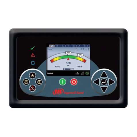
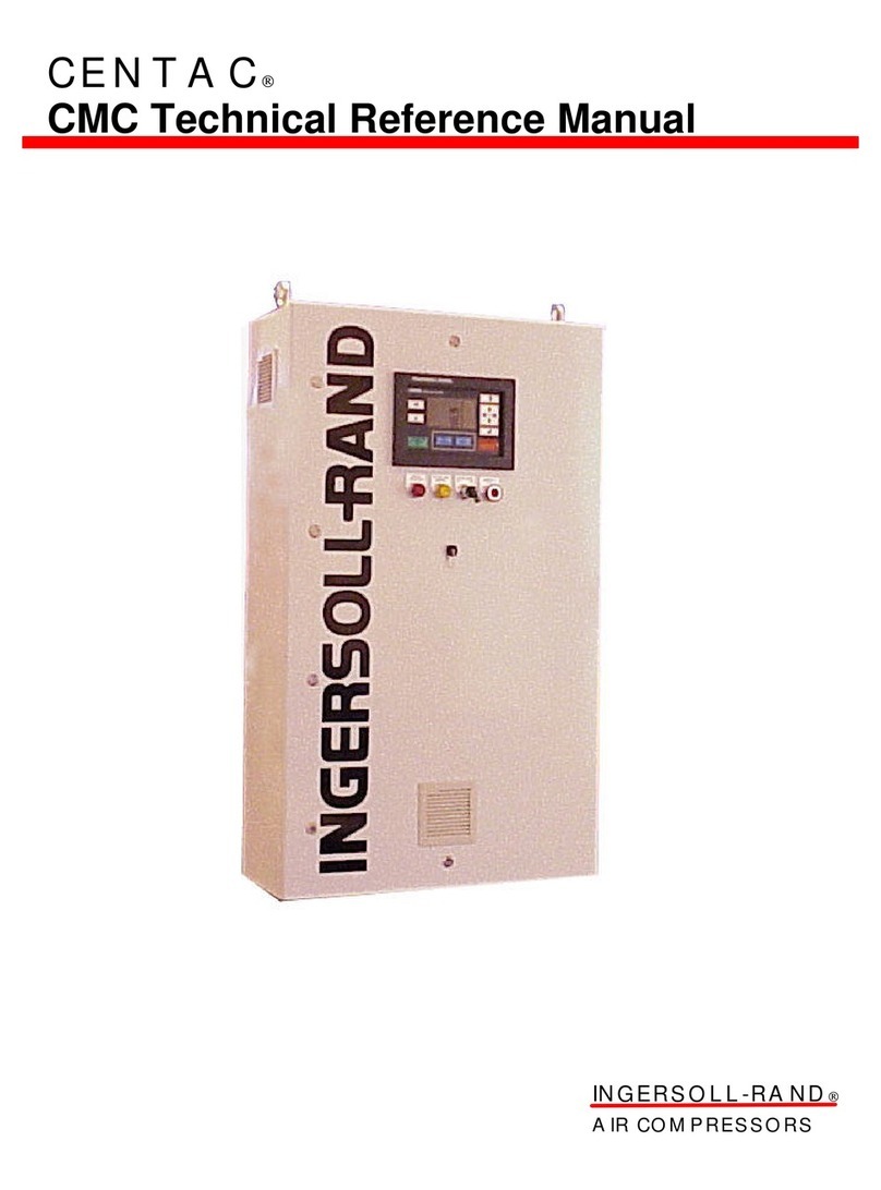
Ingersoll-Rand SG Quick start guide

Medium Industrial Systems
Davidson, North Carolina 28036
©
Ingersoll-Rand 2000
Printed in U.S.A.
Simplicity
Serviceability
Reliability SG
Control System
Technicians Guide
Form APDD672A
August 2000

CONTENTS
TOPIC PAGE
SG INTELLISYS CONTROLLER INTRODUCTION ...... 1
COMPONENT REVIEW .............................................. 2
SG INTELLISYS INPUT/OUTPUT INFORMATION .... 27
INTELLISYS CONTROLLER .................................... 29
SG DISPLAY SCREEN ............................................. 35
OPERATOR SETPOINTS ......................................... 37
OPTIONS ................................................................ 38
FACTORY SETPOINTS ............................................ 39
SENSOR CALIBRATION .......................................... 42
WARNINGS ............................................................ 43
ALARMS ................................................................. 48
STEPPER MOTOR OPERATION .............................. 54
WIRING SCHEMATICS ........................................... 65
DIAGRAMS ............................................................. 70

-1-
SG INTELLISYS CONTROLLER
INTRODUCTION
WORLDWIDE EPROM REVISION LEVEL 1.3
AND HIGHER
The Intellisys control system is an exclusive
Ingersoll-Rand design developed for reliable
compressor operation. The controller display can
be programmed in nine languages and various
unitsofmeasureforthepressureandtemperature
readings.
Themicroprocessorbasedcontrollerusesa finger
touch membrane for operation of the compressor
and setting control parameters.
Information about the current operating status is
available on a Liquid Crystal Display (LCD) from a
15-item list of temperature, pressure and filter
condition readings.
TheIntellisysmonitorsthecompressorandshould
any pre-programmed limit be exceeded, the
controller automatically displays a warning or
issues an alarm to shut the compressor down.
The major components of the control system
include the Intellisys, thePowerSupplyBoardand
aSteppingMotortopositionthecompressor’sinlet
valve.
A group of pressure and temperature sensors,
relays and switches support the decision making
process.

-3--2-
Operation of the control system will be easy
after the following explanation of the control
system components is read and understood.
The explanation follows a logical path and begins
at the primary side of the control voltage trans-
former. Use the electrical schematics provided in
this publication or the Operator’s Manual as a
guide.
COMPONENT REVIEW
1FU - Fuses
1FU is the schematic designation for identical
fuses designed for control transformer applica-
tions. Afuseisinstalledineachofthetwowires
connecting line voltage to the primary side of
the control voltage transformer (T1). These
fuses provide a degree of protection should a
short-circuit develop in the transformer.
The fuses have a time-delay feature to handle
the short duration, but very high, inrush current
when power is first applied to the transformer.
For an instant, the inrush current drawn by the
transformercan be several times greater than the
full-load rating.
These fuses are also current limiting to protect
downstream components from damage and the
magnetic effects of short-circuit currents. Current
limiting is defined as being able to cut off a
short-circuit current in less than one-half cycle
(.008 second, 60 Hz). Generally speaking, this is
long before damaging current levels are reached.
The fuses are Class CC high performance and
have a unique shape on one end to fit into a
corresponding shaped fuse holder. The shape is
intended to prevent slower response fuses from
being installed in the circuit.
Thecurrentratingofthefusesdependsonthesize
of the control voltage transformer applied to the
starter of the compressor. A chart is provided on
the electrical schematic of the compressor to
select replacement fuses.
T1 - Control Transformer
A step-down transformer (T1) reduces the in-
cominglinevoltage to levels suitable as the power
source for the Intellisys control system.
The reduced voltage levels are called secondary
connections and there are two.
One secondary circuit is rated at 120 VAC-1-60
(110 VAC-1-50) and is basically used to energize
solenoid valves and starter coils. The “hot”
connection is X2 and the neutral connection X1 is
grounded to the starter chassis.
Theother secondary circuit israted at 24VAC and
the connections are X3 and X4. This circuit is
described as an isolated secondary because
neitherX3norX4isgroundedtothechassisatthis
point.
The voltage is connected to a bridge rectifier
located on the Power Supply Board andconverted
toapproximately 33 VDC. A portionof the33 VDC
powers the stepping motor and a portion is

-5--4-
regulated down to 12 VDC and sent onward to the
Intellisys.
A connection diagram for possible primary volt-
ages is shown on the transformer and in the
Operator’s Manual. The transformer must be
connected properly to avoid control system
damage.
120/110 VAC Circuit - Transformer (T1) to
Intellisys
The Intellisys controller receives 120/110 VAC
power from T1 and, depending on operating
conditions, sends the voltage onward to specific
areas at specific times. Examples: energizing a
starter coil at start-up or energizing a solenoid
valve when the compressor loads.
The circuit begins at X2 and connects to the
Intellisys in the following sequence.
2FU - Fuse
Adualelementfuseinthe120/110VACsecondary
side of the control voltage transformer circuit to
provide a degree of protection for the Intellisys
controller.
Dual element fuses have two individual elements
inside the fuse body.
One element, a spring actuated trigger assembly,
operates on overloads up to 5-6 times the fuse
current rating. When the overload has lasted long
enough to soften a soldered area, the spring pulls
the area apart to break the circuit.
The other element, the short-circuit section,
operates on short-circuits up to the interrupting
rating of the fuse.
Achartonthecompressor’selectricalschematicis
provided to select a replacement fuse.
RFI Filter
A device within the 120/110 VAC circuit used to
filter Radio Frequency Interference (RFI) and
prevent undesirable electrical disturbances from
entering the Intellisys.
In extreme instances, RFI can cause erratic
control problems because the power supply is not
steady.
Emergency Stop Switch
Located next to the Intellisys controller in the
starter door and intended to stop the compressor
in an emergency.
The switch has two sets of normally closed
contactsthatopenwhentheredbuttonispressed.
Refer to the electrical schematic and observe one
contacttobeinthe120/110VACcircuit(ES-1)and
theother contact in the12 VDClogic circuit (ES-2)
at P3 terminals 17 and 18.
These parallel contacts ensure power is removed
from the starter coils and solenoids to cause the
compressor to stop immediately.
Theswitchremainsintheopenpositionuntilmanu-
ally reset by rotating the red button clockwise.

-7--6-
1TB - Terminal Block
A double row terminal block having 14 poles that
serveascommonconnectionpointsforwireswithin
the control system. A decal identifies the terminal
block (1TB) and each pole is numbered 1 through
14 reading from left to right.
When reading an electrical schematic, wires con-
necting to 1TB indicate which pole the wire con-
nects to. Examples: 1TB-1 is the first pole and
1TB-7 is the seventh pole.
1ATS - High Air Temperature Switch
A normally closed switch installed in the discharge
port of the airend that opens when the discharge
temperature rises above 245°F (118°C). The
mechanical switch serves as a back-up for the
usual Intellisys temperature shutdown at 228°F
(109°C).
1ATS is connected in the 120/110 VAC circuit and
should it open, the Intellisys shuts the compressor
downinanALARMconditionandcausesthewords
“Control Power Loss” to appear in the display.
1PS-InterstagePressureSwitch(2-StageUnits
/ 250-450 Horsepower)
A normally closed switch monitoring interstage
pressure on 2-stage airends and opens should
pressureexceedapproximately100psi. When the
switch opens, the Intellisys stops the compressor
in an ALARM condition and “Control Power Loss”
appears in the display. 1PS must be manually
reset.
This switch is not used on single stage compres-
sors and a jumper wire is installed at the 1TB
connection points.
P1 through P10 - Quick Connect/Disconnect
Plugs
A group of different size plug-type connectors and
mating receptacles used to attach wires to the
Intellisys. The plugs and their receptacles are
identified on the electrical schematic and back
cover of the Intellisys. The plugs are designed to
be inserted in one direction only.
The large receptacles at the lower edge of the
Intellisys are a double-row design and care must
be taken to ensure the single row plugs are
inserted at the correct location.
As an example: P3 receptacle has two rows and
each row has 16 connections.
Thefirstrowisclosetothesheetmetalstarterdoor
and numbered 1 through 16 reading left to right.
The second row is away from the sheet metal
starter door and numbered 17 through 32 reading
left to right.
Remember.... the small numbers are close to the
door, the large numbers are away from the door
and the number sequence reads from left to right.
The 120/110 VAC circuit passes through a filter
anda seriesofswitchesto connect totheIntellisys
with the X2 “hot” wire at P1-1 and the X1 neutral
wire at P1-10.

-9--8-
24 VAC Circuit - Transformer (T1) to Power
Supply Board (PCB1)
The 24 VAC power from T1 connects to a bridge
rectifier on the Power Supply Board and is
converted to 33 VDC. A portion of the 33 VDC is
used to power the stepping motor and a portion is
regulated down to 12 VDC and sent onward to the
Intellisys controller.
The circuit is between X3 and X4 and connects to
thePowerSupplyboardinthefollowingsequence.
3FU - Fuse
A fast-blow fuse on the 24 VAC secondary side of
the control voltage transformer provides a degree
ofprotectionforthePowerSupplyBoard. Thefuse
isratedat5ampsforcompressorsfittedwitheither
4 inch or 6 inch diameter inlet valves. The fuse is
rated at 6 amps for compressors fitted with 8 inch
diameter inlet valves.
The fuse is a non-time delay type and is intended
to blow instantly when either a short-circuit is
experiencedorthevoltageexceedsapproximately
38 volts AC.
The short-circuit protection is basic but the high
voltage protection works with the help of a Silicon
ControlRectifier(SCR)onthePowerSupplyBoard.
WhentheSCRsenseshighvoltage(approximately
38 volts AC), it diverts the circuit to ground and
3FU quickly blows before components beyond the
fuse, such as the stepping motor drive chips, are
damaged by high voltage.
Always use a BBS type fuse (or equivalent) rated
for the amperage required by the specific
compressor.
Power-On Light (24 VAC - Starter Door) (2LT)
A “Power-On” light is located on the starter box
door next to the Intellisys controller.
When incoming power has been applied to the
control voltage transformer and 3FU is in good
condition,thislightindicates24VACisavailableto
the Power Supply Board at J1 terminals 1 and 2.
As indicated, a “Power-On” condition exists and
care must be taken to prevent injury or damage
from contact with any part of the electrical circuit.
NEVERuseanindicatorlight toconfirmpowerhas
beenturnedoff! Afaultybulborloosewirewillgive
a false indication.
Power Supply Board (PCB1)
Aprintedcircuitboardislocatedinthemainstarter
box to supply power to the stepping motor and
Intellisys controller.
Major items on the board include diodes, a bridge
rectifier to convert 24 VAC to 33 VDC, two voltage
regulators, capacitors, resistors, two drive chips
for the stepping motor and a programmable (PAL)
chip to provide logic for the drive chips.
Thereare four plug-in junctions(J1, J2,J3 and J4)
on the board. J1 brings 24 VAC to the board from
T1 transformer, J2 sends a 12 VDC power supply

-11--10-
to the Intellisys and J4 receives input from the
Intellisystotellthedrivechipshowfarandinwhich
direction to rotate the stepping motor. J3 sends
power from the two drive chips on the Power
Supply Board to the stepping motor.
Stepping Motor (3MTR)
The stepping motor is directly connected to the
inletvalveofthecompressorandoperatesonaDC
voltage supply. The motor is bi-directional and as
itrotates,theinletvalveiseitheropenedorclosed.
The stepping motor has multiple North/South
permanent magnet poles on the rotor andtwosets
of interlaced windings in the housing. As the drive
chips send variable strength electrical pulses to
the two sets of windings, the windings are rapidly
turned on and off in an exact sequence.
As the variable pulse is applied to the two sets of
windings, one winding has an increase in pulse
strength while the other set of windings has
reduction of pulse strength. The combination of
pulse sequence and strength causes the motor to
turn in very short and precise .45°steps. The
motor can rotate either clockwise or counter-
clockwise.
Thedirection, distance and speedof rotation are a
result of the drive chips varying the pulse strength
in response to input from the Intellisys.
Stepper Limit (PCB2)
The Stepper Limit PCB2 is a printed circuit board
located on the inlet valve that limits the inlet valve
rotation to approximately 90 degrees. The board
has two optical limit switches and each emits an
infrared light beam. When the light beam is
interrupted,thecontrollerreceivesanindicationof
valve position (open or closed).
Auxiliary Contacts
Small switches mounted directly on the side of the
main motor contactors that serve to confirm the
position of the contactor or energize electrical
components.
There is a mechanical linkage between the
auxiliary contact and the main contactor. As the
main contactor closes, or opens, the mechanical
inkage causes small switches within the auxiliary
contact to change position.
The internal switches, usually two, can be nor-
mally open, normally closed or a combination of
the two.
Auxiliary contacts are identified on electrical
schematics according to which contactor they are
attached. Examples... auxiliary contact 1Sa is
attachedtocontactor1Sandauxiliarycontact2Ma
is attached to contactor 2M.
When a contactor has more than one auxiliary
contact attached, each auxiliary will be identified
on the electrical schematic as 2Ma, 2Mb, etc.
Overload Relays (1OL/2OL)
The main motor and the fan motor are each
equipped with overload relays that monitor the

-13--12-
current drawn by the motors. Should either motor
draw excessive current, the relay will open to
cause the compressor to stop. The relays are
normally closed, operate on a 12-volt DC circuit
and are shipped from the factory in the automatic
reset position. The relays are identified on
electrical schematics as 1OL for the main motor
and 2OL for the fan motor.
Basically, the overload relay has a heat-generat-
ingelement for eachofthethreephasessupplying
current to the motor. The heater element is sized
for the current drawn by the motor at full load
conditions. Should an overload condition develop
to draw higher than normal current, the heater
elements produce additional amounts of heat.
Theadditionalheatissensedbyasmallstripmade
of two dis-similar metals bonded together having
different rates of expansion. As the bi-metal strip
heats up, it bends as a result of the two different
expansion rates until it trips the overload relay
contacts to the open position. As the contacts
open, the compressor is shut down in an alarm
condition.
After cooling, the relay can be reset manually or
automatically.
Coolant Filter Differential Pressure Switch
(CPS)
A differential pressure-sensing switch is installed
to monitor the condition of the coolant filter. The
switchisnormallyopenandclosesacrossa12volt
DC circuit when the filter differential exceeds 20
psi.
Emergency Stop - Logic Circuit (ES-2)
A normally closed contact in the 12 volt DC circuit
that opens when the Emergency Stop button is
pressed. As the contact opens, power is removed
from the controller circuit. See the emergency
stop switch section for further information.
Remote Stop Button (RSP) (Optional)
The button is intended to stop a running com-
pressor from a remote location.
When the Remote Start/Stop option is installed
and turned on in the set point routine, a normally
closed switch must be connected between P3
terminals 19 and 20. The switch must be a
momentary opening type (approximately .1
second). If a start attempt is made while the
switch remains open, the controller will issue a
Remote Stop alarm.
Remote Start Button (RST) (Optional)
Thebuttonisintendedto start a stopped compres-
sor from a remote location.
When the Remote Start/Stop option is installed
and turned on in the set point routine, a normally-
open switch must be connected between P3
terminals 21 and 22. The switch must be a
momentaryclosingtype(approximately2seconds).
ARemote Start alarm will be issued by the control-
ler if the button is not released by the end of the
star-delta transition time on star-delta units or 7

-15--14-
seconds after the button is pressed on full-voltage
starters.
Pressure Sensors - 1AVPT, 3APT, 4APT, 5CPT
and 6APT
Pressuretransducersusedtoconvertairpressure
signalstoavoltagesignalbetween.5and4.5volts
DC.
The transducer contains a metal diaphragm
connected to a small piece of steel called the
beam which in turn has a strain gauge attached.
As pressure pushes the diaphragm, the beam
flexes and bends the strain gauge.
A continuous 5 volt DC supply is attached to the
strain gauge assembly.
As the strain gauge bends due to the changing
pressure on the diaphragm, the resistance value
throughthestraingaugechangesacorresponding
amount. The result is a variable output signal that
ranges from .5 volts DC to 4.5 volts DC.
The output signal is processed by an analog-to-
digital converter within the Intellisys controller.
Depending on the voltage level, decisions are
made by the Intellisys that may cause a change in
the pressure reading on the display panel, unload
the compressor or possibly shut the compressor
down if conditions dictate.
If a pressure sensor is replaced, it is important to
calibrate the new sensor. Basically, calibration
allows the controller to read the sensor’s output
signal with the diaphragm in a totally relaxed state
and then correct for any minor deviations from .5
volts DC. Calibration directions are included in the
Operator’s Manual.
Therearenoadjustmentstothepressuresensors.
1AVPT - Inlet Vacuum
A pressure sensor having a range between 0 and
15 psi vacuum connected to the airend inlet to
providevacuuminformationforthecontroller. The
output voltage is .5 volts DC at 0 psi vacuum and
4.5 volts DC at 15 psi vacuum.
The controller uses inlet vacuum information to
confirm the drive motor is rotating in the correct
direction, to indicate the condition of the inlet air
filter and to provide logic for positioning the inlet
valve during modulation or unloaded operation.
3APT - Separator Tank Pressure
A pressure sensor applied to a range between
0 and 225 psi used to provide information
aboutpressurewithinthecompressor’sreceiver-
separator tank. The connection point in the
receiver-separator tank is referred to as sump
pressure. The sump pressure is taken on the wet
side (before air enters) the separator element.
The sump pressure is monitored for several
reasons to include comparison to line pressure
during the separator element differential check
and to provide logic for the controller to position
the inlet valve during unloaded operation.
The normal unloaded sump pressure is maintained

-17--16-
within a range of 24 to 33 psi to ensure adequate
coolantflowandallowtheunloadedcompressorto
operate at a low horsepower condition.
4APT - Package Discharge Pressure
A pressure sensor applied to a range between 0
and 225 psi used to provide information about the
discharge pressure just prior to the compressed
air leaving the package. The connection is down-
stream of the aftercooler and in the top of the
moisture separator.
Packagedischargepressureprovideslogictoload
or unload the compressor and is compared with
the sump pressure during the separator element
differential check.
5CPT-InjectedCoolantPressure(2StageCom-
pressors Only)
Apressuresensorphasedintoproductionapproxi-
mately mid-May, 2000 and applied to a range
between 0 and 225 psi to provide information
about the pressure of the coolant/lubricant at the
injection port on 2 stage compressors.
5CPT will cause a “Low Coolant Pressure” alarm
(!)tobeissuedifthecompressorisrunningandthe
coolant pressure falls below 1 psi and either the
sump pressure is greater than 10 psi or the inlet
vacuum is less than 12 psi.
DO NOT enable this option if coolant pressure
5CPT is not installed. This will cause a 5CPT
Failure alarm (!).
6APT Separator Delta-P Sensor
A sensor phased into production approximately
mid-May, 2000 to replace the Separator Solenoid
(8SV). The separator delta-p-sensor is enabled
through the Options set point routine.
When the sensor is enabled, the Intellisys will
measure the separator element pressure drop by
subtracting the dry side sump pressure (6APT)
from the wet side sump pressure (3APT).
DO NOT enable this option if the separator
element sensor (6APT) is not installed. This will
result in an incorrect measurement and a 6APT
warning (?).
Temperature Sensors - 2CTT, 2ATT and 4ATT
Temperaturesensitiveresistorscalledthermistors
used to monitor temperature changes at various
points within the compressor package. They
operate on a 5 volt DC circuit.
As the temperature of the sensor changes, either
higher or lower, the resistance through the sensor
changes a corresponding amount.
As the output voltage varies due to the tempera-
turechanges,thevoltagestrengthisprocessedby
an analog to digital converter within the controller.
Depending on the output voltage from the various
sensors, the controller makes decisions that may
change a number on the panel display, delay a
differential pressure reading until the compressor
warms up, reposition the inlet valve slightly during

-19--18-
cold unloaded operation, provide a Warning about
rising temperature or could possibly shut the
compressor down with an Alarm if operating
conditions dictate.
2CTT - Injected Coolant Temperature Sensor
A temperature sensor monitoring the injected
coolant flow into the airend. The injected coolant
absorbs heat generated during the air compres-
sion,lubricatesmovingpartsandsealsclearances
between the rotors and the housing.
When Injected Temperature has been selected on
the Current Status display, 2CTT provides the
information to the controller.
Whenacompressorisoperatingunloadedandthe
injectedcoolanttemperatureisbelow120°F(49°C),
2CTT provides information to the controller which
automaticallyopenstheinletvalveasmallamount.
Opening the inlet valve a small amount raises the
unloaded sump pressure approximately 20 psi to
promote flow of the cold coolant.
As the injected coolant temperature rises above
120°F (49°C), the controller recloses the inlet
valve the small amount to return the unloaded
sump pressure to the 24 to 33 psi range.
2CTT also provides information to the controller
duringchecksoftheCoolantFilterconditiononthe
Current Status display.
When the injected coolant temperature is below
120°F (49°C) during the Coolant Filter check on a
running unit, the controller assumes the cold
coolant will be more viscous and the pressure
differential across the filter will be higher than
normal. As a result, the controller will advise “Unit
Too Cold” in the display until the injected coolant
temperature rises above 120°F (49°C).
2ATT - Airend Discharge Temperature Sensor
A temperature sensor monitoring the temperature
of the air/coolant mixture as the flow leaves the
airend discharge port. Typically, this sensor is
located adjacent to the flange area of the
discharge housing and just before the air/coolant
mixture enters the airend discharge check valve.
When Airend Discharge Temperature has been
selected on the Current Status display, 2ATT
provides the information to the controller.
Should 2ATT observe the airend temperature
exceed 97% of the 228°F (109°C) High Airend
Discharge Temperature alarm, the controller will
place the symbol ( ? ) and the airend discharge
temperature in the Current Status display. The
compressor continues to run during the tempera-
ture Warning.
If the airend discharge temperature continues to
rise, 2ATT advises the controller of the condition
andwhenthetemperatureexceeds228°F(109°C),
the controller shuts the compressor down. The
Current Status display will show the symbol ( ! )
followed by the words High Airend Discharge
Temperature and the shutdown temperature.

-21--20-
4ATT - Package Discharge Temperature
Sensor
Monitors the temperature of the compressed air
downstream of the compressor’s aftercooler.
Typically, this sensor is located in the top of the
moisture separator.
When Package Discharge Temperature has been
selected on the Current Status display, 4ATT
provides the information to the controller.
This sensor is for temperature information only
and has no Warning or Alarm feature.
P7 - Communications Port
A plug-in port to connect the controller to an
Intellisys System Controller (ISC) or an Intellisys
Remote Interface (IRI).
P8 - Expansion Port
Used for Integral Sequencing.
P9 - Option Module Port
Thisplug-inportreceivesthe5-pinoptionmodules
thataddlogictothecontroller.Themodulescanbe
factory or field installed and are indexed to be
inserted in one direction only. After the module
has been installed, it must be activated in the
setpoint routine. See the Operator’s Manual for
details.
Four option modules are available for compres-
sors built with Intellisys controllers containing
EPROM revision level 1.23 and lower:
Automatic Start/Stop
Remote Start/Stop
Automatic Start/Stop with Remote Start/Stop
Automatic Start/Stop with Remote Start/Stop and
Power Outage Restart Option (PORO)
Compressors equipped with Worldwide EPROM
revision level 1.3 and higher require an option
module for power outage restart option (PORO)
only.
P1 - Power and Triac Output Plug
A ten terminal plug that receives 120/110 VAC
from control transformer T1 and sends 120/110
VAC power to starter and solenoid coils. The
power to the coils is controlled by a group of triacs
under the direction of the controller.
Triacs are solid-state devices that act as switches
toenergizeorde-energizethestarterandsolenoid
coils.
The power circuit begins with the “hot” wire
connectedatP1-1and the neutral, or ground wire,
is connected at P1-10.
The presently used triac outputs to the star-delta
starter coils are indicated on the electrical
schematic as Output 1 and Output 2. Full-voltage
starters use Output 1 only.
The blowdown solenoid valve (3SV) is energized
andde-energizedbyOutput4oneithertypestarter.

-23--22-
Larger units may have two solenoids (3SVa and
3SVb) wired parallel.
Triac output 3 is for the fan motor starter (if used),
output 8 operates the optional PORO horn.
Outputs 5, 6 and 7 are reserved for other special
uses.
Starter Logic - Full Voltage
When the controller places the message “Ready
ToStart”inthe left side of thedisplayand the Start
button is pressed, the following takes place.
Triacoutput1sends 120/110voltsAC tothecoilof
1M. As 1M pulls in, the mechanical action of the
main contactor causes auxiliary contact 1Ma to
close between P3 terminals 7 and 8. This closure
of 1Ma confirms 1M physically pulled in as
directed.
At the instant 1Ma closes, 1Mc also closes to
energize the coolant stop solenoid (5SV). Had the
compressor been water-cooled, the water shut-off
solenoid (4SV) would also be energized at this
time.
1Mc has an arc suppressor (RC-3) wired across
the contacts to eliminate any power surges that
might disrupt adjacent low voltage circuits. Refer
to the full-voltage electrical schematic in the
Operator’s Manual.
The compressor motor (1MTR) and the fan motor
(2MTR) are now running.
Had the controller not seen 1Ma close, it assumes
there is a problem within the starter coil circuit
(such as a loose wire or faulty triac) and issues an
alarm. At that time, the words “ALARM” and
“Starter Fault” appear in the Current Status
display.
When the Stop button is pressed, 1M contactor
becomes de-energized and opens. As 1M opens,
the controller confirms 1Ma also opened or a
Starter Fault alarm will be issued.
The coolant stop solenoid (5SV) is de-energized
as 1Mc opens at the same time.
The previously described starting and stopping
activity is basically the same for Automatic Start/
Stop,Remote Start/Stop orPower Outage Restart
(PORO).
Starter Logic - Star-Delta
When the controller places “Ready To Start” in the
left side of the display and the Start button is
pressed, the following takes place.
Triac output 2 sends 120/110 volts AC through a
set of normally closed auxiliary contacts (2Mb) to
the coil of contactor 1S.
As 1S pulls in, the mechanical action of the
contactor causes auxiliary contact 1Sa to close
between P3 terminals 9 and 10. The closure of
1Sa confirms to the controller that 1S did physi-
cally pull in as directed.
Contactor 1S has a total of four auxiliary contacts
and the function of the remaining three must be

-25--24-
understood.
At the same instant 1Sa closed, auxiliary contact
1Sb also closed to complete a yet to be energized
circuit to the coil of contactor 1M.
Also at the same instant, auxiliary contacts 1Sc
and 1Sd opened to electrically isolate the coil of
contactor 2M.
Atthistime, the only energizedcontactor coil is 1S
and triac output 2 energized it. Refer to the
star-delta electrical schematic in the Operator’s
Manual.
However, just 50 milliseconds after 1S pulled in,
triac output 1 activates to send 120/110 volts
throughthenowclosedauxiliarycontact1Sbtothe
coil of contactor 1M.
As 1M pulls in, the mechanical action of the
contactor causes auxiliary contact 1Ma to close
betweenP3 terminals 7 and 8. The closure of1Ma
confirms to the controller that 1M contactor did
physically pull in as directed.
Contactor1Mhasatotalofthreeauxiliarycontacts
and the function of the remaining two must be
understood.
At the same instant 1Ma closed, auxiliary contact
1Mb also closed and, in effect, created a parallel
circuit with auxiliary contact 1Sb.
Also at the same instant, auxiliary contact 1Mc
closedtoenergizethecoolantstopsolenoid(5SV).
Ifthecompressoriswaterorremoteaircooled,the
water shut-off (4SV) and remote cooler pressure
relief solenoid (7SV) would also be energized.
Auxiliary contact 1Mc has an arc suppressor (RC
3) wired across the contacts to eliminate any
power surges that might disrupt adjacent low volt-
age circuits. Refer to the star-delta electrical
schematic in the Operator’s Manual.
At this time, contactor 1S is energized by triac
output 2 and contactor 1M is energized by triac
output 1.
The compressor motor (1MTR) is now connected
in the star connection and accelerating at a
reduced internalvoltage and reduced torque. The
acceleration time is generally in the ten second
range and controlled by an adjustable timer in the
controller’s setpoint routine.
The fan motor (2MTR) is running at full voltage
conditions.
At the end of the ten second time interval, triac
output 2 removes the 120/110 volt AC supply to
de-energize the coil of contactor 1S.
As contactor 1S opens, the mechanical action
causes auxiliary contacts 1Sa and 1Sb to open
and auxiliary contacts 1Sc and 1Sd to close.
1Saopenedthe confirmation circuit at P3termi-
nals 9 and 10 and 1Sb opened half of the parallel
circuit originally supplying voltage to the coil of
contactor 1M.
The closing of 1Sc and 1Sd cause contactor 2M to
become energized.

-27--26-
Auxiliary contacts 1Sc and 1Sd each have an arc
suppressor wired across the contacts to eliminate
any power surges that might disrupt adjacent low
voltage circuits.
As 2M becomes energized, auxiliary contact 2Ma
closes between P3 terminals 9 and 10. The clo-
sure of 2Ma confirms to the controller that 2M did
pull in as directed.
Note:thereisashortdelaybetweentheopeningof
1Sa and the closing of 2Ma to prevent nuisance
Starter Fault alarms during the transition period.
Contactor 2M has a total of two auxiliary contacts
and the function of the remaining auxiliary contact
must be understood.
At the same instant auxiliary contact 2Ma closed,
auxiliarycontact2Mbopenedtoelectricallyisolate
the coil of contactor 1S.
The compressor motor (1MTR) is now connected
inthedeltaconnectionatfullspeedandfulltorque.
P2 - Remote Alarm Contact
A relay having a normally-open contact and a
normallyclosedcontactthatchangepositionwhen
the controller issues an Alarm.
Customer supplied voltage through the contacts
can operate a remote light or horn. The contact is
rated at 5 amps and 250 volts AC.
When the alarm condition has been corrected and
the Intellisys reset, the contacts return to their
original position.
SG INTELLISYS INPUT/OUTPUT
INFORMATION
WORLDWIDE EPROM REVISION LEVEL 1.3
AND HIGHER
The standard Intellisys controller requires input
from several sources to control the compressor.
Analog-To-Digital Inputs *
Inlet Vacuum - 1AVPT
Separator Tank Pressure - 3APT
Package Discharge Pressure - 4APT
Injected Coolant Pressure - 5CPT
Separator Delta-P Sensor - 6APT
Injected Coolant Temperature - 2CTT
Airend Discharge Temperature - 2ATT
Package Discharge Temperature - 4ATT
* Analog-To-Digital inputs are voltage
measurements that have been converted
to digits (numbers) for the display.
Switched Inputs *
Starter Interlock - 1Ma (N.O.)
Starter Interlocks - 1Sa and 2Ma (N.O.)
Main Motor Overload - 1OL (N.C.)
Fan Motor Overload - 2OL (N.C.)
Emergency Stop Button - 2 contacts - (N.C.)
Coolant Filter Differential Switch (N.O.)
Remote Start (N.O.)
Remote Stop (N.C.)
Stepper Limit Switches (2)
Interstage Pressure Switch (2 Stage Only) -
(N.C.)
Line Voltage Monitor (Optional) - (N.O.)

-29--28-
* Switched inputs are the action of contacts
opening or closing within the circuit. The
Stepper Limit switches are solid-state de-
vices but the effect is the same. There is a
1-second delay on all switched inputs.
Triac Outputs *
Out 1 - Energizes contactor coils 1M and 2M
Out 2 - Energizes contactor coil 1S
Out 4 - Energizes solenoid(s) 3SVa and 3SVb
Out 7 - Energizes Remote Warning (?) Relay
Out 8 - Energizes Optional PORO Horn
* Triacs are solid-state switches to energize
or de-energize starter and solenoid coils.
INTELLISYS CONTROLLER

-31--30-
EMERGENCY STOP
Pressing this switch stops the compressor imme-
diately. The compressor can not be restarted until
the switch is manually reset. Turn the switch knob
clockwise to reset.
POWER ON LIGHT
This indicates the control voltage and the line
voltage are available for starting.
The operator panel is divided into two areas. The
bottom row of four buttons provides direct control
over the starting, stopping, unloading and loading
of the compressor. These are defined by the
symbols printed on the buttons themselves, as
shown here.
START
Pressingthisbuttonwillstartthecompressorifthe
display shows "Ready To Start". The compressor
will start and load if there is sufficient demand for
air.
STOP
Pressingthisbuttonwillactivatetheunloadedstop
sequence. If the compressor is running loaded, it
will unload and continue to run unloaded for an
adjustable 10 to 30 seconds and then stop. If the
compressor is running unloaded, it will stop
immediately.
UNLOAD
Pressing this button will cause the compressor to
unload and remain unloaded. The display will
indicate the machine is "Running Unloaded", and
"Mode: UNLOAD".
LOAD
Pressing this button will cause the compressor to
load if the compressor is running and if the
"Discharge Pressure" is less than the "Online
Pressure". This also returns the machine to the
operating mode that is specified by the "Mode of
Operation" set point.
The other five buttons provide access to various
operator-selectable functions and machine oper-
ating conditions. The purpose of each of these
buttons is defined by the display screen and the
particular function being performed at that time.
EMERG
STOP
POWER
ON

-32-
ARROWS
These up and down buttons have multiple func-
tionsrelating to the righthalf of the displayscreen.
When lists are presented, the buttons are used to
moveupordownthroughtheitemsonthelist. The
small arrrow(s) displayed in the upper right corner
of the display screen indicate when you can move
up (designated by arrow head pointing up) and/or
down (designated by arrow head pointing down)
through the list.
When the value of a specific machine operating
parameter is highlighted on the display screen for
thepurposeofchangingthatvalue,thebuttonsare
used to change the value itself.
DISPLAY BUTTONS
The functions of the three buttons below the
display screen change and are defined by the
words immediately above them in the bottom line
ofthescreen. Eachfunction,suchasMAINMENU,
STATUS, SET, etc., is described in appropriate
sections in this manual.

-33-
on individual page
to large for 8-1/2 x 11
Table of contents
Other Ingersoll-Rand Control System manuals
Popular Control System manuals by other brands

American Standard
American Standard AccuLink Platinum 1040 Installation & user guide

Index
Index ABC 2 Series operating instructions

John Crane
John Crane API PLAN 74 STEAM Installation, operation & maintenance instructions

MTHTrains
MTHTrains DCS manual

Genius
Genius JA108 Instructions for use

Roland
Roland R1000 series E20 manual

Spectral
Spectral SMART CONTROL IR-LINK-SYSTEM quick start guide

Horizon Hobby
Horizon Hobby Spektrum FIRMA Smart ESC Series manual

Triple Plus
Triple Plus CLM-COAMAP-1-02 quick start guide

NELSEN WATER
NELSEN WATER NRO ROC2HE-UL manual

Deif
Deif DELOMATIC 4 Series Replacement instructions

Wilo
Wilo Control ESK Series Installation and operating instructions