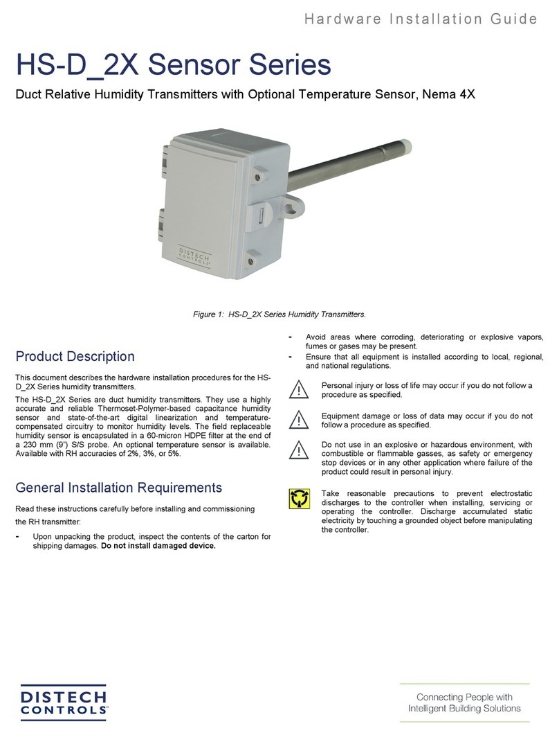
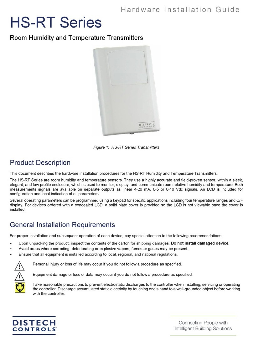
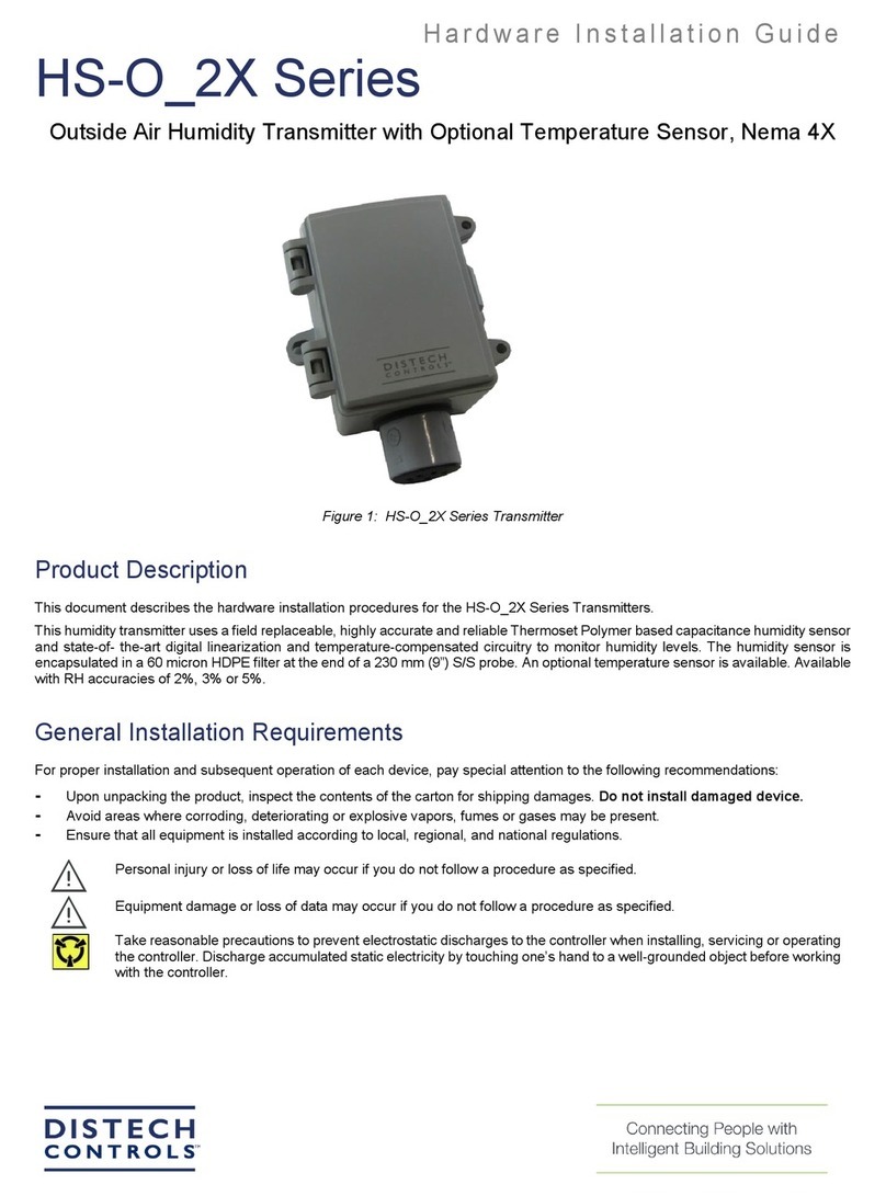
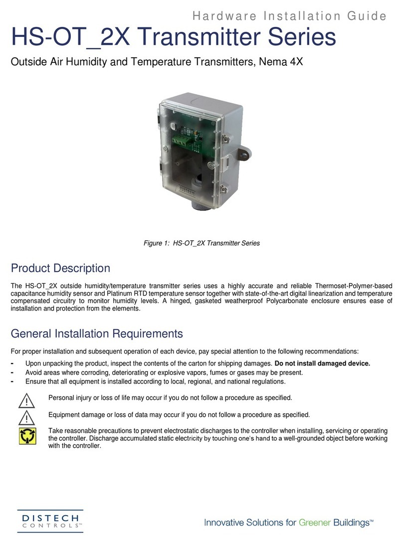
Distech Controls PS-2AEULDP Series User manual

Installation Guide
PS-2AEULDP Series
Ultra Low Pressure Transmitter
Figure 1: PS-2AEULDP Ultra Low Pressure Transmitter
Product Description
This document describes the hardware installation procedures for the PS-2AEULDP Ultra Low Pressure Transmitter. The Ultra-Low Pressure Transmitter
can be used to measure positive, negative or differential pressure in the ranges of 0.1”wc to 0.4”wc and 25 Pa to 100 Pa. The pressure sensor technology
is based on thermal flow measurement of gas through a micro-flow channel within the sensor chip, which results in superior sensitivity for ultra low
pressures. The extremely low gas flow through the sensor ensures high immunity to dust contamination, humidity and long tubing.
The device features field selectable current or voltage output signal types and can be set for unidirectional or bidirectional pressure measurements for the
most flexible application. Typical HVAC applications include monitoring of filter differential pressure or clean room pressure. The output signal is factory
calibrated and temperature compensated for highest start-up accuracy and trouble-free operation.
General Installation Requirements
For proper installation and subsequent operation of each device, pay special attention to the following recommendations:
- Upon unpacking the product, inspect the contents of the carton for shipping damages. Do not install damaged device.
- Avoid areas where corroding, deteriorating or explosive vapors, fumes or gases may be present.
- Ensure that all equipment is installed according to local, regional, and national regulations.
Personal injury or loss of life may occur if you do not follow a procedure as specified.
Equipment damage or loss of data may occur if you do not follow a procedure as specified.
Take reasonable precautions to prevent electrostatic discharges to the controller when installing, servicing or operating
the controller. Discharge accumulated static electricity by touching one’s hand to a well-grounded object before working
with the controller.

2/5
Mounting Instructions
The transmitter mounts on a vertical surface using the two integrated mounting holes. Ensure there is enough space around the unit to connect the
pressure tubing without kinking and avoid locations with severe vibrations or excessive moisture. The two mounting holes will facilitate a #10 size screw
(not supplied). See Figure 2. It should be mounted on a vertical surface with the pressure ports on the bottom and the cable entrance on the left.
Figure 2: Enclosure Mounting.
The enclosure has a hinged cover with a latch. Open the cover by pulling slightly on the latch on the bottom of the enclosure and at the same time pulling
on the cover, as illustrated in Figure 3.
Figure 3: Opening enclosure.
A 1/2" NPT threaded connection hole is provided on the side of the enclosure. Screw the EMT connector or cable gland connector in until tight. See Figure
4. It is recommended that weatherproof conduit or cable gland fittings be used. Optional 1/2" NPT to M16 thread adapter and cable gland fitting installation,
see Figure 4.
Figure 4: Cable installation.
Make wiring connections as per the “Wiring” illustrations. Swing door closed until securely latched. For added security, 2 screws are provided that may be
installed in the integrated screw tabs. See Figure 5.
Figure 5: Door security latch.

3/5
Wiring
The transmitter has standard screw block connectors and easy wire access to facilitate wiring. It is recommended that shielded twisted pair wiring at least
22 AWG be used for all connections and that the device wires not be run in the same conduit with wiring used to supply inductive loads such as motors.
Disconnect the power supply before making any connections to prevent electrical shock or equipment damage. Make all connections in accordance with
national and local electrical codes.
The device power (24 Vac/dc) is connected to the terminal marked PWR. This terminal is used for the positive dc voltage or the hot side of the ac voltage.
The device is reverse voltage protected and as such will not operate if connected backwards.
The common of the power supply is connected to the terminal marked COM. Note that this device has a half-wave type power supply which means the
power supply common is the same as the output signal common. Therefore, several devices may be connected to one power supply and the output signals
all share the same signal common. Use caution when grounding the secondary of an ac transformer or when wiring multiple devices to ensure that the
circuit ground point is the same on all devices and the controller.
The analog output signal is available on the OUT terminal. This signal is jumper selectable for either a voltage or a 4-20 mA output signal type. These
options are clearly indicated on the device circuit board. The analog output signal is typically connected directly to the Building Automation System (B.A.S.)
and used as a control parameter or for logging purposes.
For voltage type output signal the device has a minimum load that it is able to drive, similarly for current type output signal the device has a maximum load
that it is able to drive with a particular power supply voltage. Observe and follow these ratings in the Specification section or inaccurate reading may result.
The 4-20 mA output signal can easily be converted to a 1-5 Vdc signal for controllers accepting this type of input. Simply insert a 250 ohm (0.1% is best)
resistor between the “+” and “-” inputs of the controller. This will convert the 4-20 mA signal to the desired 1-5 Vdc.
Figure 6: Configuration Settings.

4/5
Configuration
The transmitter is configured with jumpers located on the circuit board as shown on the PCB drawing. These jumpers are used to select the output signal
type and the bipolar range/unipolar range (+/- or 0-MAX.) The unit is factory configured to operate in the 4-20 mA output mode. This can be changed to
the voltage mode by moving the jumper from the position marked 4-20 to the position marked VOUT.
For example, if the model is for 25 Pa and if the jumper labeled (+/-) is also selected, then the pressure range will be –25 to +25 Pa. This means that each
model has two pressure ranges, a bipolar range +/-, and a unipolar range, 0-MAX.
Pneumatic Connections
The two pressure ports on the end of the enclosure are labeled High and Low. The output signal reads a positive value when the port pressure is higher
on the High port than the Low port so ensure these ports are connected correctly. Use 1/8” to 3/16” ID flexible tubing for the pressure connections. Arrange
the tubing to minimize stress on the connections and ensure there are no kinks in the tubing. For most accurate measurements, do not leave the Low port
open to the atmosphere, run a return line from the Low port to the vicinity of the point being measured.
Ensure the tubing to be used is clean and do not allow material to fall into the pressure ports as contamination could damage the sensor. When removing
tubing use care to avoid breaking the ports. In some cases it is better to cut the tubing off rather than pulling it off but be careful not to cut the fitting or an
air leak may occur.
Power Up Instruction
Before turning on the power, verify all wiring to ensure that it complies with one of the included wiring diagrams and verify that the output signal type is
correctly selected with the jumpers. Also, review the specifications to ensure the power supply is correct and that the pressure is within the correct range.
At this time, also inspect the internal pressure tubing that connects the sensor to the external ports to ensure that the tubing did not get kinked during
installation.
Proper operation can be verified by measuring the output signal. For voltage output configuration, measure the voltage between the OUT and COM
terminals. The voltmeter should read between 0-10 Vdc. For current output configuration, insert a mA meter in series with the OUT terminal. The mA meter
should read between 4 and 20 mA.
Operation
If the unit is set to a unipolar range such as 0-25 Pa, then the pressure applied to the High port must be higher than the pressure applied to the Low port.
In this case, if the Low port is left open to ambient pressure and the High port is used to measure a positive pressure, then the output pressure can be
calculated as follows:
4-20 mA
Pressure = [(Output current - 4 mA) / 16 mA] x Range
0-10 Vdc
Pressure = (Output voltage / 10 V) x Range
In the case of 0-25 Pa, 4 mA or 0 V = 0 Pa and 20 mA or 10 V = 25 Pa. Since the transmitter is linear, 12.5 Pa would be 12 mA or 5 V. If the positive
pressure connection is reversed then the transmitter will always output 4 mA or 0 V.
If the unit is set to a bipolar range such as ± 25 Pa, then the pressure applied to the High port should be higher than the pressure applied to the Low port
for a positive output response. In this case, differential pressure can be measured using both ports. If the High port has a positive pressure with respect
to the Low port, then the output indicates a positive pressure. Negative pressure is indicated if the High pressure is less than the Low pressure. For bipolar
ranges, the output pressure can be calculated as follows:
4-20 mA
Pressure = [(Output current - 4 mA) / 16 mA] x Range- Offset
0-10 Vdc
Pressure = (Output voltage / 10 V) x Range- Offset

©, Distech Controls 2020 All rights reserved.
While all efforts have been made to verify the accuracy of information in this manual, Distech Controls is not responsible for damages or claims arising from the use of this
manual. Persons using this manual are assumed to be trained HVAC specialist / installers and are responsible for using the correct wiring procedures and maintaining safe
working conditions with fail-safe environments. Distech Controls reserves the right to change, delete or add to the information in this manual at any time without notice.
Distech Controls, the Distech Controls logo, and Innovative Solutions for Greener Buildings are trademarks of Distech Controls. All other trademarks are property of their
respective owners.
5/5 PS-2AEULDP_IG_10_EN
Dimensions
Table of contents
Other Distech Controls Transmitter manuals
