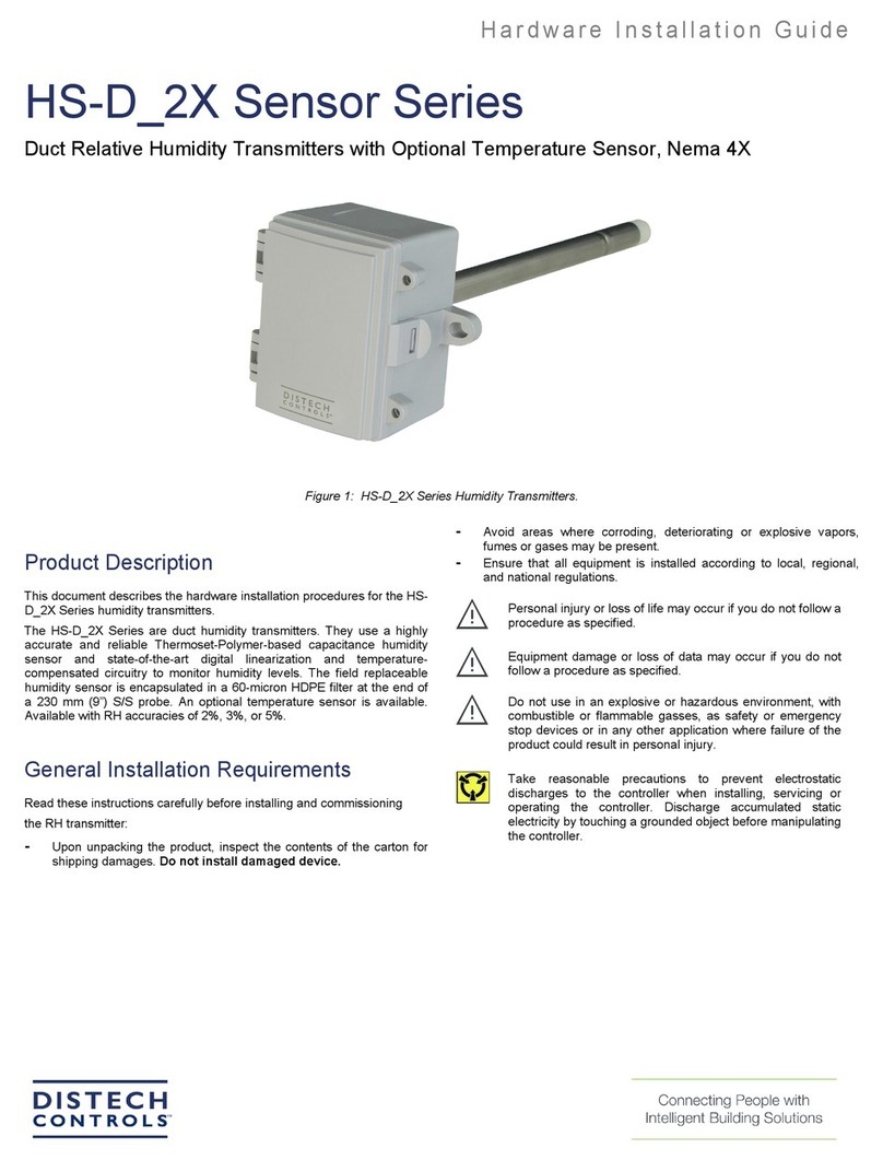
Distech Controls HS-RT Series Manual

Hardware Installation Guide
HS-RT Series
Room Humidity and Temperature Transmitters
Figure 1: HS-RT Series Transmitters
Product Description
This document describes the hardware installation procedures for the HS-RT Humidity and Temperature Transmitters.
The HS-RT Series are room humidity and temperature sensors. They use a highly accurate and field-proven sensor, within a sleek,
elegant, and low profile enclosure, which is used to monitor, display, and communicate room relative humidity and temperature. Both
measurements signals are available on separate outputs as linear 4-20 mA, 0-5 or 0-10 Vdc signals. An LCD is included for
configuration and local indication of all parameters.
Several operating parameters can be programmed using a keypad for specific applications including four temperature ranges and C/F
display. For devices ordered with a concealed LCD, a solid plate cover is provided so the LCD is not viewable once the cover is
installed.
General Installation Requirements
For proper installation and subsequent operation of each device, pay special attention to the following recommendations:
- Upon unpacking the product, inspect the contents of the carton for shipping damages. Do not install damaged device.
- Avoid areas where corroding, deteriorating or explosive vapors, fumes or gases may be present.
- Ensure that all equipment is installed according to local, regional, and national regulations.
Personal injury or loss of life may occur if you do not follow a procedure as specified.
Equipment damage or loss of data may occur if you do not follow a procedure as specified.
Take reasonable precautions to prevent electrostatic discharges to the controller when installing, servicing or operating
the controller. Discharge accumulated static electricity by touching one’s hand to a well-grounded object before working
with the controller.

2/6
Mounting
The room type sensor is installed directly on a standard electrical box, or mounted directly to the wall. The backplate is configured for
compatibility with many types of electrical boxes. It should be mounted approximately five feet from the floor of the area to be
controlled. Do not mount the sensor near doors, windows that open, supply air- diffusers or other known air disturbances. Avoid areas
where the sensor is exposed to vibrations or rapid temperature changes.
The cover is hooked to the base at the top edge, and must be removed from the bottom edge first. Use a small screwdriver to carefully
pry each bottom corner, if necessary. If a security screw is installed on the bottom edge, then it will need to be loosened or removed.
Tip the cover away from the base and set it aside.
The pcb must be removed from the base to access the mounting holes. Follow typical anti-static procedures when handling the pcb
and be careful not to touch or bend the sensors. To remove the pcb, press the tab on the enclosure base to unsnap the latch near the
bottom edge, then lift the pcb out of the base. Set the pcb aside until the base is mounted on the wall.
After the base is screwed to an electrical box or the wall, using the appropriate holes, pull the wires through the wiring hole in the
center of the pcb and then gently reinstall it in the enclosure base. Ensure the pcb is snapped into the base securely and correctly.
The mounting hole locations are shown in the dimensions drawing.
Figure 2: HS-RT Sensors Mounting
Wiring
Deactivate the 24 Vac/dc power supply until all connections are made to the device to prevent electrical shock or equipment damage.
Follow proper electrostatic discharge (ESD) handling procedures when installing the device, otherwise equipment damage may occur.
Use 22 AWG shielded wiring for all connections, and do not locate the device wires in the same conduit with wiring used to supply
inductive loads, such as motors. Connect the cable shield to ground at the controller, only. Make all connections in accordance with
national and local codes.
For 4-20 mA two-wire loop-powered operation, only the POWER and OUTPUT terminals are required if a DC power supply is used.
The COMMON terminal is only used for AC power or for a voltage output signal type. If the signal type is set to voltage, or a 24-volt
AC power supply is used, connect the positive dc voltage or the hot side of the ac voltage to the terminal marked POWER, and connect
the power supply common to the terminal marked COMMON. The device is reverse voltage protected and will not operate if connected
backwards.
For three-wire voltage output operation, connect either an AC or DC power supply to POWER and COMMON, and the voltage output
signal is available on the OUTPUT terminal with respect to COMMON.
Ensure the controller Analog Input (AI) matches the sensor output signal type before power is applied, and that the pcb switches are
set
correctly for the required signal type. The current signal has a maximum load that it can drive, and the voltage signal has a minimum
load rating. Follow the ratings in the Specification section or inaccurate readings may result.
This device has a half-wave power supply so the power supply common is the same as the signal common. Several devices may be
connected to one power supply and the output signals all share the same common. Use caution when grounding the secondary of a
transformer or when wiring multiple devices to ensure the ground point is the same on all devices and the controller.
The override switch output is a dry-contact and is available on the SWITCH + and SWITCH – terminals and typically connects to a
low voltage digital input of the controller to indicate room occupancy or override when the button is activated. The five-position fan

3/6
speed output signal is configured with five different resistive values and is available on the FAN + and FAN – terminals. The LED input
is typically powered by a 5 Vdc digital output from the controller and connects to the LED + and LED - terminals. The resistive slide-
pot setpoint output signal is available on the SETPNT + and SETPNT – terminals and can be configured with various resistance
values and the operation can be set for forward or reverse acting. The external jack is internally connected to a four-pin terminal block
labeled 1, 2, 3 and 4, and accepts a four-pin header connector for remote communication with the controller. An optional resistive
temperature sensor may also be included, and is connected to the TEMP + and TEMP - terminals. Contact the factory to configure
options before ordering.
Start-up
Verify that the sensor is properly wired, connections are tight, and the mA / Vdc switch is in the correct position. For voltage output,
also ensure the 5V / 10V switch is set correctly for the required signal type. Apply power and note that the LCD will begin displaying
the RH level (ifinstalled). The output signals will also be available immediately after start-up.
Output signal
The RH output is scaled such that 4-20 mA (or 0-5 or 0-10 Vdc) equals0-100 %RH and is temperature compensated over the full 0-
50 °C temperature range. The temperature output is scaled such that 4-20 mA (or 0-5 or 0-10 Vdc) equals either 0-35 °C, 32-95 °F,
0-50 °C or 32-122 °F depending on which range is selected in the menu. The factory default range is 0-35 °C.
Functions
Terminal
Function
POWER
From +24 Vac/dc of controller or power supply
COMMON
To GND or COMMON of controller
OCC IN
From digital output of controller
TEMP OUT
RH output to analog input of controller
4-20 mA or 0-5/0-10 Vdc
RH OUT
RH output to analog input of controller
4-20 mA or 0-5/0-10 Vdc
SWITCH +
Override switch + to digital input of controller
SWITCH - Override switch - to COMMON of controller

4/6
Setup Menu
The menu has several items as shown below. The device cover must be removed to access the menu. To enter the menu,
press and release the
<MENU> key while in normal operation. This will enter the Setup Menu step 1, pressing the <MENU> key a second time advances
to step 2. Each pressof the <MENU> key advances the menu item.
The <UP> and <DOWN> keys are used to make changes to program variables by scrolling through the available options. When a
value is changed, usethe <MENU> key to save it to memory and advance to the next menu item. No changed values are saved
unless you press the <MENU> key.
Setup Menu operation is explained below, and factory default values are illustrated.
<MENU> Press and release the <MENU> key to enter the Setup Menu
1.
C/F
The temperature scale defaults to Celsius (°C). It can be changed to Fahrenheit (°F) by using the <UP> or <DOWN> keys. This
setting will affect otherparameters.
<MENU>
2.
Temperature Range
Two temperature ranges are available for both °C and °F, 0-35 °C (32-95 °F) or 0-50 °C (32-122 °F). This can be changed with
<UP> or <DOWN>.This item depends on the C/F setting.
<MENU>
3.
Temperature Offset
Use <UP> or <DOWN> to add or subtract an offset to the temperature output signal and display. The default is 0 but can be
changed from –9 to +9 °Ffor temperature calibration.
<MENU>
4.
RH Offset
Use <UP> or <DOWN> to add or subtract an offset to the RH output signal and display. The default is 0 but can be changed from –
20 to +20 %RH forhumidity calibration.

5/6
<MENU>
5.
Display Mode
Select parameters to display on the LCD. 1 = Temperature only, 2 = RH only and 3 = T + RH alternately every 2 seconds.
Change with <UP> or
<DOWN>.
<MENU>
6.
Output Signal
Default is 5 for 0-5 Vdc output signal. Can change with <UP> or <DOWN> to 10 for 0-10 Vdc outputs. This only applies for models
with voltage outputs.
<MENU>
7.
OCC Reverse
The default OCC signal type is active low (Lo). Can change with <UP> or <DOWN> to active high (HI) to reverse the OCC
action. By default, shortingthe OCC input to common will turn on the OCC LCD segment.
<MENU>
8.
Backlight Enable
Use the <UP> or <DOWN> keys to enable or
disable the LCD backlight.bL1 = backlight on,
bL0 = backlight off.
<MENU> Exits the Setup Menu and returns to normal operation.

©, Distech Controls Inc. 2022 All rights reserved.
Distech Controls is not responsible for damages or claims arising out of improper or careless installation or handling of its products. Persons using this manual are
assumed to be trained HVAC specialist / installers and are responsible for using the correct wiring procedures and maintaining safe working conditions with fail-
safe environments.
Global Head Office - 4205 place de Java, Brossard, QC, Canada, J4Y 0C4 - EU Head Office - ZAC de Sacuny, 558 avenue Marcel Mérieux, 69530 Brignais, France
6/6 HS-RT Series_IG_12_EN
Dimensions
Dimensions shown in inches (millimeters).
Table of contents
Other Distech Controls Transmitter manuals
Popular Transmitter manuals by other brands

Evikon
Evikon E2660-CO-CO2 user manual

Sennheiser
Sennheiser SR 300 IEM manual
AMG
AMG AMG4723-CWDMn-MP instruction manual
Datexel
Datexel DAT 1111 installation instructions
Williams Sound
Williams Sound Whisper T863 Instructions for use & care
ULFA TECHNOLOGY
ULFA TECHNOLOGY JANITOR PDT Series instruction manual
