Ditch Witch W12 HYDROVAC User manual

W12
Operator’s
Manual
CMW® 053-10036
Issue 1.0
Original Instruction

W12 Operator’s Manual Overview - 1
Overview
Chapter Contents
Serial Numbers Location . . . . . . . . . . . . . . . . . . . . . 2
Intended Use . . . . . . . . . . . . . . . . . . . . . . . . . . . . . . 2
Method of Operation . . . . . . . . . . . . . . . . . . . . . . . 3
Equipment Modification . . . . . . . . . . . . . . . . . . . . . 3
Major Components . . . . . . . . . . . . . . . . . . . . . . . . . 5
Air Flow Diagram . . . . . . . . . . . . . . . . . . . . . . . . . . . 7
Water Flow Diagram . . . . . . . . . . . . . . . . . . . . . . . . 8
• Winterization System . . . . . . . . . . . . . . . . . . . . . . . . . . . . . . . . . . . . . . . . . .9
Operator Orientation . . . . . . . . . . . . . . . . . . . . . 10
Operating Area . . . . . . . . . . . . . . . . . . . . . . . . . . . 10
California Proposition 65
Diesel engine exhaust and some of its constituents are known to the State of California to
cause cancer, birth defects, and other reproductive harm www.P65warnings.ca.gov.
W12 Operator’s Manual Overview - 2
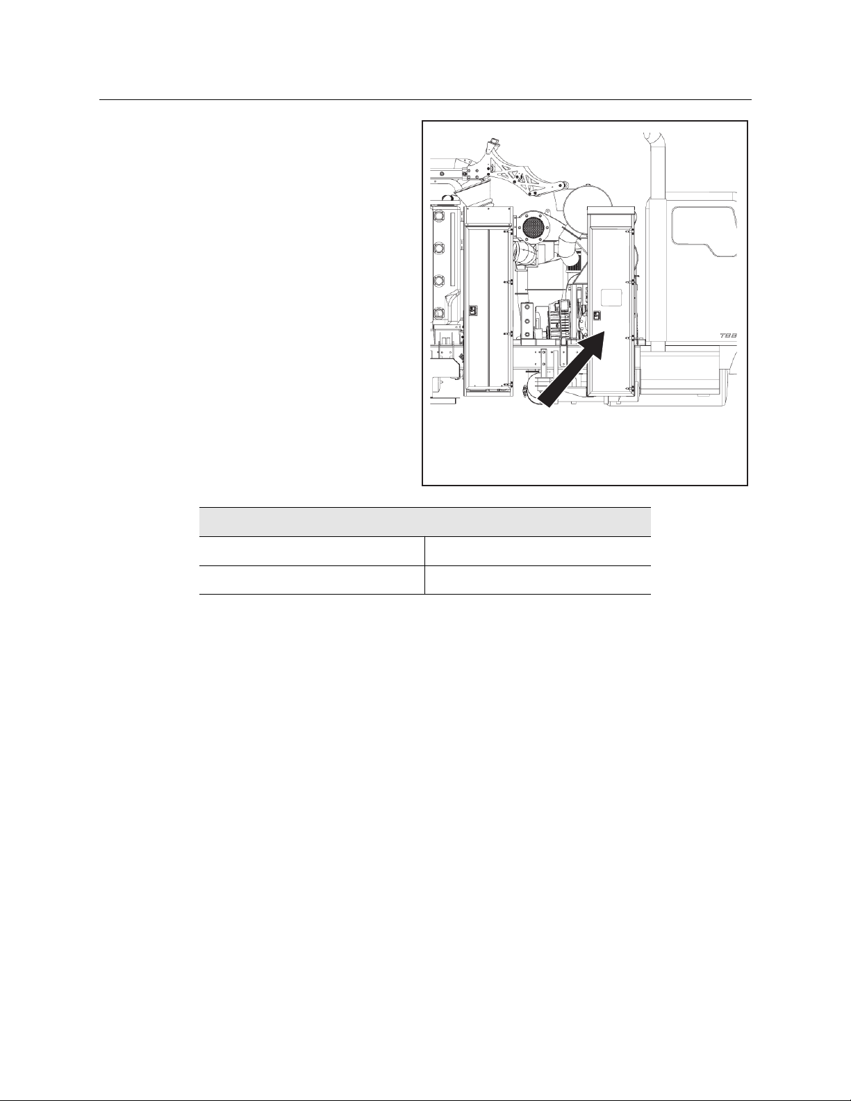
Serial Numbers Location
Serial Numbers Location
Record serial numbers and date of purchase in
spaces provided. Serial numbers for the major
components are on a data plate mounted on the
inside of the control panel door, as shown.
Intended Use
The W12 Hydrovac Truck is a vacuum excavation machine capable of vacuuming and transporting a wide
variety of nonhazardous, non-flammable liquid and solid debris.
This machine is designed to perform efficient soft excavation, including exposing utilities for visual
verification and potholing. The optional air system on the W12 can operate auxiliary pneumatic tools on
low (100 psi/689 kPa) setting.
This machine is intended for operation only according to the instructions in this manual. Operate machine
in ambient temperatures from 0° to 115°F (-18° to 46°C). Contact your Ditch Witch® dealer for provisions
required for operating in extreme temperatures. Use in any other way is considered contrary to the
intended use.
This machine should be operated, serviced, and repaired only by professionals familiar with its particular
characteristics and acquainted with the relevant safety procedures.
Item
Build No.
Date of purchase
TTW12-OV-003a
DATA PLATE LOCATED INSIDE
CONTROL PANEL DOOR

W12 Operator’s Manual Overview - 3
Method of Operation
Method of Operation
The vacuum system has the capability of conveying material by two (2) modes. The first mode is “pure
vacuum”. The second mode is “air conveying”.
1. Pure Vacuum
As a general rule, pure vacuum would be used for removing sludge from beneath liquid or for rapid
liquid loading. In this mode, the vacuum tube is totally submersed in the liquid and only material (no
air) transports through the line. Although this type of material transfer CAN be done with a Positive
Displacement Blower, we need to understand that we are not actually creating “vacuum” where
pressure is created. When plugging the line solid, the blower is pulling air from the tank and replacing
it with product or the opening is obstructed. In this instance, we have a “vacuum” situation only while
the dig tube is completely full of product. Once that seal is broken, air is now moving through the
system as an “air conveyance.”
2. Air Conveyance
The second conveying method is “air conveyance” and requires enough air velocity going past the
material to be picked up to capture such, and convey it through the suction tube to the body. This
requires the vacuum pump be operating at a fast enough speed to produce the required airflow to
capture the material. Vacuum tube lengths up to one thousand (1000) feet can be used and liquid
loading rates up to five hundred (500) GPM through a six (6) inch line can be realized.
There are also applications where a vacuum fluidizing nozzle could be used. This combines the benefits of
pure vacuum and air conveyance. The fluidizing nozzle has the ability to remove sludge from beneath
liquids where the distance exceeds the limitation of pure vacuum.
Equipment Modification
This equipment was designed and built in accordance with applicable standards and regulations.
Modification of equipment could mean that it will no longer meet regulations and may not function
properly or in accordance with the operating instructions. Modification of equipment should only be
NOTICE: The vacuum system is designed for liquids, slurries, and damp materials. Dry or dusty
materials must be wet down before vacuuming. This can be accomplished by connecting one of the
water hose reels to the debris tank misting port.
NOTICE: It should also be noted that the vacuum pump temperature should be closely monitored to
avoid damage to the pump when attempting to load material in this fashion.
NOTICE: It should be noted that for maximum efficiency, all vacuum line connection points must be air
tight. Any leaks or breaks in the system will automatically eliminate the ability to create “pure vacuum”
and you are now back in an “air conveyance” situation. During air conveyance with “wet” materials,
static buildup is minimal.

W12 Operator’s Manual Overview - 4
Equipment Modification
made by competent personnel possessing knowledge of applicable standards, regulations, equipment
design functionality/requirements and any required specialized training.
W12 Operator’s Manual Overview - 5
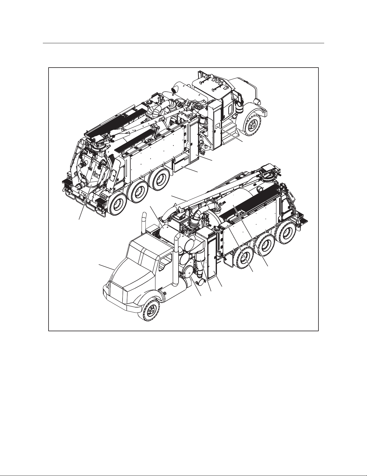
Major Components
Major Components
1. Truck Chassis
2. Water Tanks
3. Debris Tank
4. Boom
5. Silencer
6. Cyclone
7. Water Heater
8. Air Compressor (optional)
9. Dust Filter
10. Control Panel and Remote Control
11. Manual Control Levers
12. Rear Door
13. Safety Equipment Storage Cabinet
14. Blower (not shown)
15. Transfer Case (not shown)
16. Water Pump (not shown)
TTW12-OV-005a
1
12
4
8
7
10
5
2
9
13
6
3

W12 Operator’s Manual Overview - 6
Major Components
Item Description
1. Truck Chassis Diesel truck chassis (see “Specifications” on page 128 for detailed
information on the truck chassis).
2. Water Tanks Four interconnected polyethylene tanks equipped with sight gauges and
drain valves hold clean water for use during excavation operations. Total
water capacity is 1,200 gallons.
3. Debris Tank Water and debris is captured in the debris tank. The tank has a capacity of
12 cubic yards of material. It is also designed as a Tip-Tank style of debris
tank, operating like a dump truck to facilitate the off-loading of debris. It is
equipped with a hydraulically actuated dump door and locking system, as
well as a vacuum boot connection system, that seals the vacuum duct
when the tank is lowered down. The debris tank has a port in the top to
visually check tank level or take samples. Two gate valves in the rear door
can also be used to discharge water and debris. The door is equipped with
dual safety locks to keep the door in the open position for cleaning and
maintenance.
4. Boom A hydraulically operated boom is used to vacuum dirt, water, and debris
during excavation operations. The boom is controlled either manually or
via a remote control. Multiple dig tubes are provided to extend the reach
of the boom during excavation.
5. Silencer Two silencers direct air flow to minimize environmental noise levels.
6. Cyclone Two cyclonic separators direct the air flow in a circular path, where
centrifugal force causes the airborne materials to be separated from the
air stream and drop out.
7. Water Heater The water heater provides hot water for excavation operations in cold
weather. The water heater is fueled using diesel fuel from the truck fuel
tank.
8. Air Compressor (Optional) A high pressure air dig system, based on a hydraulically driven
compressor system, is available. The air compressor provides pressurized
air to the air lance.
9. Control Panel and
Remote Control
The main control panel for the W12 is located in a cabinet on the curb side
of the truck. This cabinet also stores the Remote Control (with charging
cradle) and the truck scale.
10. Manual Controls Manual control levers for the boom, debris tank lift, rear door, and other
functions are located on the curb side near the rear of the truck.
11. Blower The blower creates the primary air movement creating suction through
the boom. The blower is driven by the transfer case.
12. Transfer Case The transfer case is installed in a split-shaft configuration on the truck
driveshaft. Outputs of the transfer case drive the hydraulics of the truck
and the blower.

W12 Operator’s Manual Overview - 7
Air Flow Diagram
Air Flow Diagram
Suction is created by the flow of air through the system, driven by the blower. The twin lobe helix screw
air blower is driven by the transfer case, which is in turn driven by the truck’s drive shaft. The blower
draws air (and water and debris) into the debris tank through the boom. The air is eventually exhausted
back to the atmosphere. The following steps describe the air flow through the W12 truck in more detail.
The figure below shows a simplified diagram of the air flow through the W12 truck.
1. The operator uses a high pressure dig wand or compressed air lance to break up the soil. The blower
draws air (and water and debris) into the debris tank through the boom which is eventually exhausted
back to atmosphere through the discharge silencer. Material is picked by the end of the suction hose
and the air stream moves it into the debris tank. The suction hose is supported by a boom which the
operator can raise, lower, extend, retract, or rotate left or right.
2. The material travels through the boom and enters the debris tank, where liquids and large debris fall
out of the air stream. A pair of shutoff float balls will cut off the air stream if the debris tank gets full.
3. The air stream then travels through the crossover and enters the two cyclonic separators. Centrifugal
force causes the airborne materials to be separated from the air stream. These particles will fall into a
particulate trap located at the bottom of the cyclonic filters. Clean air exits out the top of the
separator and travels into the plenum.
4. From the plenum, the air enters a final dust filter. The dust filter is a pleated element capable of ten
(10) micron filtration. It will capture any remaining dust. From the dust filter, the clean air travels back
to the blower.
5. The ducting for the blower has two inlets. One draws in the air from the dust filter, while the other
brings in cool air from the exterior of the truck via the cool air intake silencer.
6. Air exits the system through the a high efficiency discharge silencer.
13. Water Pump The pump provides pressurized water at up to 3,000 PSI for excavation
operations. It is driven by a hydraulic motor mounted on the transfer case.
Item Description
TTW12-OV-002b.ai
COOLING
INTAKE
SILENCER
DISCHARGE
SILENCER
BLOWER
DUST
FILTER PLENUM
VACUUM
BREAKER
CROSSOVER
SHUTOFF
DEBRIS TANK
BOOM
PARTICULATE
TRAP
CYCLONIC
SEPARATORS
W12 Operator’s Manual Overview - 8
Water Flow Diagram
7. In the event of a clog in the system that blocks or reduces suction, the vacuum breaker can be
activated. This diverts the system intake from the boom and opens it to the atmosphere. This cuts off
suction through the boom and debris tank, allowing the operator to clear the clog without the need
to shut down the blower. The vacuum breaker is activated using the operator’s remote control.
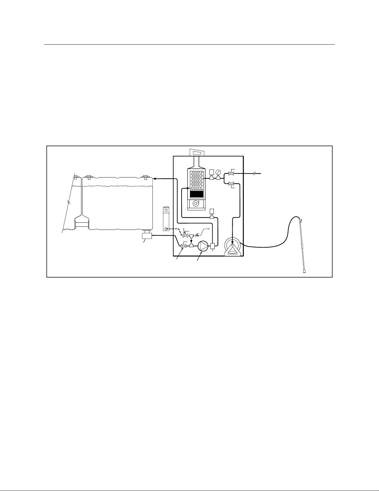
Water Flow Diagram
The W12 truck has four interconnected water tanks for clean water. This water is supplied to the high-
pressure water wands that are used by the operators for excavating. The figure below shows a simplified
diagram of the water flow through the W12 truck.
1. Clean water is stored in the water tanks, and feeds through the shutoff valve to the hydraulically-
driven pump.
2. From the pump it passes through the unloader valve to the supply line for the water heater.
3. Hot water exits the water heater, passes through the temperature gauge and pressure gauge to a pair
of control valves.
4. The front and rear water valves control flow to the corresponding hose reels. The operator can open
one or both valves depending on the task.
5. To avoid pressure surges in the system, a bypass line returns water to the water tanks whenever the
operators close the hand valves on the hot water wands. This reduces wear and tear on the pump.
TTW12-OV-001a.ai
HOT WATER
JET WAND
PUMP
WATER
HEATER
FRONT
BALL
VALVE
HAND
VALVE
REAR
WATER
VALVE
FRONT
WATER
HOSE REEL
WATER TANKS
T
SHUTOFF
WATER TANK
CROSSOVER
MANIFOLD
BOILER CABINET
P
UNLOADER
BYPASS
SUPPLY
TO REAR WATER
HOSE REEL
GLYCOL
TANK
PURGE
WINTERIZATION

W12 Operator’s Manual Overview - 9
Water Flow Diagram
Winterization System
There are two parts of the winterization system installed on the W12 truck. There is a crossover manifold
below the clean water tanks. Hot water from the truck engine is routed through the manifold and heats
the connection between the two front water tanks. For winterization of the water heater, hose reels, and
hot water wands, the truck has a winterization fluid tank connected to the water system. Once operations
are completed, the operators can close the shutoff valve upstream of the water pump, and open the
winterization valve. This supplies the winterization fluid to the pump, which circulates it through the
system. To purge the system of the winterization fluid, an air connection is provided. The operator closes
the winterization valve and the shutoff valve, then holds the purge valve open until all the winterization
fluid is purged out of the hot water wands.

W12 Operator’s Manual Overview - 10
Operator Orientation
Operator Orientation
1. Front
2. Right side (Curb side)
3. Rear
4. Left side (Road side)
Operating Area
Operate within easy access of controls and/or
remote control.
About This Manual
This manual contains information for the proper use of this machine. Cross references such as “See page
50” will direct you to detailed procedures.
Bulleted Lists
Bulleted lists provide helpful or important information or contain procedures that do not have to be
performed in a specific order.
Numbered Lists
Numbered lists contain illustration callouts or list steps that must be performed in order.
IMPORTANT: Top view of machine is shown.
TTW12-OV-004a.ai
FRONT
REAR
RIGHT
(CURB SIDE)
LEFT
( ROAD SIDE)

W12 Operator’s Manual Foreword - 11
Foreword
This manual is an important part of your equipment. It provides safety information and operation
instructions to help maintain your Ditch Witch® equipment.
Read this manual before using your equipment. Keep it with the equipment at all times for future
reference. If you sell your equipment, be sure to give this manual to the new owner.
If you need a replacement copy, contact your Ditch Witch dealer. If you need assistance in locating a
dealer, visit our website at www.ditchwitch.com or write to the following address:
The Charles Machine Works, Inc.
ATTN: Marketing Department
PO Box 66
Perry, OK 73077-0066
USA
The descriptions and specifications in this manual are subject to change without notice. The Charles
Machine Works, Inc. reserves the right to improve equipment. Some product improvements may have
taken place after this manual was published. For the latest information on Ditch Witch equipment, see
your Ditch Witch dealer.
Thank you for buying and using Ditch Witch equipment.
Reporting Safety Defects
If you believe that your vehicle has a defect which could cause a crash or could cause injury or death, you
should immediately inform the National Highway Traffic Safety Administration (NHTSA) in addition to
notifying the Product Safety Manager at The Charles Machine Works, Inc.
If NHTSA receives similar complaints, it may open an investigation, and if it finds that a safety defect exists
in a group of vehicles, it may order a recall and remedy campaign. However, NHTSA cannot become
involved in any individual problems between you, your Ditch Witch dealer, or The Charles Machine Works,
Inc.
To contact NHTSA you may either call the Auto Safety Hotline toll-free at 1-888-327=4236 (TTY: 1-800-
424-9153), go to http://www.safercar.gov, or write to:
Administrator
NHTSA
1200 New Jersey Avenue S.E.
Washington, DC 20590
You can also obtain other information about motor vehicle safety from http://www.safercar.gov.

W12 Operator’s Manual Foreword - 12
W12
Operator’s Manual
Issue number 1.0/OM-2/2023 Part
number 053-10036
Copyright 2023
by The Charles Machine Works, Inc.
and Ditch Witch are registered trademarks of The Charles Machine Works, Inc.
This product and its use may be covered by one or more patents at http://patents.charlesmachine.works.

W12 Operator’s Manual Contents - 13
Contents
Overview 1
Machine serial number, information about the type of work this machine is designed
to perform, basic machine components, and how to use this manual
Foreword 11
Part number, revision level, and publication date or this manual, and factory contact
information
Safety 14
Machine safety alerts and emergency procedures
Prepare 27
Procedures for preparing jobsite, preparing operator, and preparing equipment
Controls 36
Machine controls, gauges, and indicators and how to use them
Vacuum and Pothole Operations 71
Procedures for removing debris and potholing utility locations
Complete the Job 95
Procedures for restoring the jobsite and rinsing and storing equipment
Maintenance 98
Maintenance intervals and instructions for this machine including lubrication,
replacement of wear items, and basic maintenance
Specifications 128
Machine specifications including weights, measurements, power ratings, and fluid
capacities
Support 130
The warranty policy for this machine and procedures for obtaining warranty
consideration and training

W12 Operator’s Manual Safety - 14
Safety
Chapter Contents
Safety Alert Classifications . . . . . . . . . . . . . . . . . . 15
Guidelines . . . . . . . . . . . . . . . . . . . . . . . . . . . . . . . 16
Emergency Procedures . . . . . . . . . . . . . . . . . . . . . 17
• Electric Strike Description. . . . . . . . . . . . . . . . . . . . . . . . . . . . . . . . . . . . . .17
• If an Electric Line is Damaged. . . . . . . . . . . . . . . . . . . . . . . . . . . . . . . . . . .17
• If a Gas Line is Damaged . . . . . . . . . . . . . . . . . . . . . . . . . . . . . . . . . . . . . . .18
• If a Fiber Optic Cable is Damaged . . . . . . . . . . . . . . . . . . . . . . . . . . . . . . .18
• If Machine Catches on Fire . . . . . . . . . . . . . . . . . . . . . . . . . . . . . . . . . . . . .18
Machine Safety Alerts . . . . . . . . . . . . . . . . . . . . . . 19
• Truck, Driver’s Side . . . . . . . . . . . . . . . . . . . . . . . . . . . . . . . . . . . . . . . . . . .19
• Debris Tank Door. . . . . . . . . . . . . . . . . . . . . . . . . . . . . . . . . . . . . . . . . . . . .21
• Rear Control Panel . . . . . . . . . . . . . . . . . . . . . . . . . . . . . . . . . . . . . . . . . . .22
• Air Compressor and Water Heater Cabinet . . . . . . . . . . . . . . . . . . . . . . .23
• Control Panel Cabinet . . . . . . . . . . . . . . . . . . . . . . . . . . . . . . . . . . . . . . . .25
For additional precautions, see “Prepare” chapter.

W12 Operator’s Manual Safety - 15
Safety Alert Classifications
Safety Alert Classifications
These classifications and the icons defined on the following pages work together to alert you to situations
which could be harmful to you, jobsite bystanders or your equipment. When you see these words and
icons in the book or on the machine, carefully read and follow all instructions. YOUR SAFETY IS AT STAKE.
Watch for the three safety alert levels: DANGER, WARNING and CAUTION. Learn what each level means.
indicates a hazardous situation that, if not avoided, will result in death or serious injury.
This signal word is to be limited to the most extreme situations.
indicates a hazardous situation that, if not avoided, could result in death or serious injury.
indicates a hazardous situation that, if not avoided, could result in minor or moderate
injury.
Watch for two other words: NOTICE and IMPORTANT.
NOTICE indicates information considered important, but not hazard-related (e.g., messages relating to
property damage).
IMPORTANT can help you do a better job or make your job easier in some way.

W12 Operator’s Manual Safety - 16
Guidelines
Guidelines
Follow these guidelines before operating any jobsite equipment:
• Complete proper training.
• Read and understand operator’s manual before using equipment.
• Wear personal protective equipment including long pants, hard hat, eye protection, hearing
protection, and protective footwear.
• Do not wear jewelry or loose clothing.
• Mark proposed path with white paint and have underground utilities located before working. In the
US or Canada, call 811 (US) or 888-258-0808 (US and Canada). Also contact any local utilities that do
not participate in the One-Call service. In countries that do not have a One-Call service, contact all
local utility companies to have underground utilities located.
• Classify jobsite based on its hazards and use correct tools and machinery, safety equipment, and work
methods for jobsite.
• Mark jobsite clearly and keep spectators away.
• Review jobsite hazards, safety and emergency procedures, and individual responsibilities with all
personnel before work begins. Safety videos are available from your Ditch Witch dealer or at
www.ditchwitch.com/safety. Safety Data Sheets (SDS) are available at www.ditchwitch.com/support.
• Fully inspect equipment before operating. Repair or replace any worn or damaged parts. Replace
missing or damaged safety shields and safety alert signs. Contact your Ditch Witch dealer for
assistance.
• Follow instructions on all safety alert signs on machine.
• Use equipment carefully per the instructions in this manual. Stop operation and investigate anything
that does not look or feel right.
• Do not operate machine where flammable gas may be present.
• Only operate equipment in well ventilated areas.
• Always tie down equipment and properly stow accessories, even if traveling short distances.
• Contact your Ditch Witch dealer if you have any questions about operation, maintenance, or
equipment use.
• Complete the equipment checklist located at www.ditchwitch.com/safety.
Misuse of machine can cause death or serious injury.
Read and understand operator’s manual and all other safety instructions
before use. Know how to use all controls.

W12 Operator’s Manual Safety - 17
Emergency Procedures
Emergency Procedures
Before operating any equipment, review emergency procedures and check that all safety precautions
have been taken.
Electric Strike Description
When working near electric cables, remember the following:
• Electricity follows all paths to ground, not just path of least resistance.
• Pipes, hoses, and cables will conduct electricity back to all equipment.
• Low voltage current can injure or kill. Many work-related electrocutions result from contact with less
than 440 volts.
Most electric strikes are not noticeable, but indications of a strike include:
• power outage
• smoke
• explosion
• popping noises
• arcing electricity
If any of these occur, assume an electric strike has occurred.
If an Electric Line is Damaged
If you suspect an electric line has been damaged, DO NOT MOVE and DO NOT TOUCH ANY EQUIPMENT.
Take the following actions. The order and degree of action will depend on the situation.
• If you are operating the machine, immediately RELEASE CONTROLS.
• If you must leave the area, take small steps with feet close together to reduce the hazard of being
shocked from one foot to the other.
• Warn people nearby that an electric strike has occurred. Instruct them to leave the area.
Underground utilities. Contact can cause death or
serious injury. Locate and verify underground utilities before digging or
drilling.
EMERGENCY SHUTDOWN: Shut off truck by turning the ignition switch off, or press one of the
emergency stop buttons. One is located on the main control panel and another is located on the rear
of the truck. You can also press the red button on the remote control.

W12 Operator’s Manual Safety - 18
Emergency Procedures
• Have someone contact electric company to shut off power.
• If you leave the area, do not return to jobsite or allow anyone into area until given permission by
utility company.
If a Gas Line is Damaged
If you suspect a gas line has been damaged, take the following actions. The order and degree of action will
depend on the situation.
• Immediately shut off engine(s), if this can be done safely and quickly.
• Remove any ignition source(s), if this can be done safely and quickly.
• Warn others that a gas line has been cut and that they should leave the area.
• After warning others to leave the area, leave jobsite as quickly as possible.
• Immediately call your local emergency phone number and utility company.
• If jobsite is along street, stop traffic from driving near jobsite.
• Do not return to jobsite until given permission by emergency personnel and utility company.
If a Fiber Optic Cable is Damaged
Do not look into cut ends of fiber optic or unidentified cable. Vision damage can occur. Contact utility
company.
If Machine Catches on Fire
Perform emergency shutdown procedure and then take the following actions. The order and degree of
action will depend on the situation.
• Immediately move battery disconnect switch (if equipped and accessible) to disconnect position.
• If fire is small and fire extinguisher is available, attempt to extinguish fire.
• If fire cannot be extinguished, leave area as quickly as possible and contact emergency personnel.

W12 Operator’s Manual Safety - 19
Machine Safety Alerts
Machine Safety Alerts
Truck, Driver’s Side
1Silica dust. Exposure can cause lung
disease. Use breathing protection.
2Silica dust. Exposure can cause lung
disease. Use breathing protection.
3Hot parts. Contact can cause burns. Only
touch when cool or wear gloves.
4Moving parts. Contact can cause serious
injury. Stay away.
TTW12-SA-003a
3 54
8
67
6
9
21
Table of contents


