Dive System Kirby Morgan 300-145 User manual
Diver’s Manifold Block
Product Part #s 300-145, 300-150, 300-155
User Guide
Document Part #: 100-134
Kirby Morgan Dive Systems, Inc.
1430 Jason Way
Santa Maria, CA 93455, USA
Telephone (805) 928-7772, FAX (805) 928-0342
E-Mail: KMDSI@KirbyMorgan.com, Web Site: www.KirbyMorgan.com
Guide prepared by: KMDSI
© ⅯⅯⅩⅢ Kirby Morgan Dive Systems, Inc. Document # 130329001
Kirby Morgan Manifold Block
2 © Copyright ⅯⅯⅩⅢ Kirby Morgan Dive Systems, Inc. All rights reserved. Document # 130329001
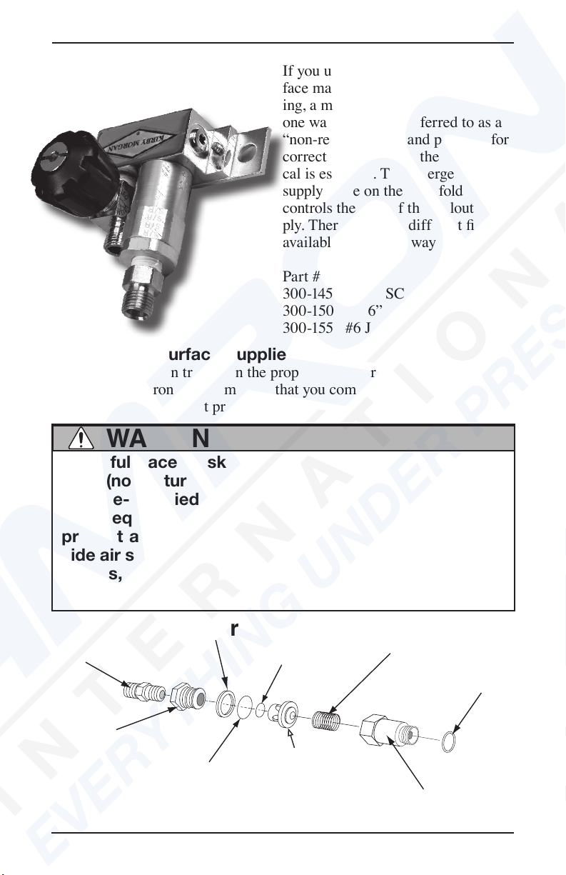
If you use an EXO-26 or other full
face mask for surface-supplied div-
ing, a manifold block which has a
one way valve (also referred to as a
“non-return” valve) and provides for
correct attachment of the umbili-
cal is essential. The emergency gas
supply valve on the manifold block
controls the ow of the bailout sup-
ply. There are three different ttings
available on the one way valve:
Part #
300-145 9/16” SCUBA tting
300-150 9/16” oxygen tting
300-155 #6 JIC tting
Diving in the Surface-supplied Mode
If you have not been trained in the proper use of surface-supplied diving
equipment we strongly recommend that you complete a training course in
the use of this equipment prior to diving surface-supplied.
Many full-face masks are not equipped with a one way
valve (non-return valve) as supplied from the factory. For
surface-supplied diving, the diver must use a manifold
block equipped with a one way valve. This will help to
prevent a “squeeze” in the event of a loss of the top-
side air supply. Without this valve, if a squeeze like this
occurs, the diver will suffer serious personal injury or
death.
WARNING
Adapter
Seat
Wiper
O-ring
O-ring
Poppet
Spring
Body
O-ring
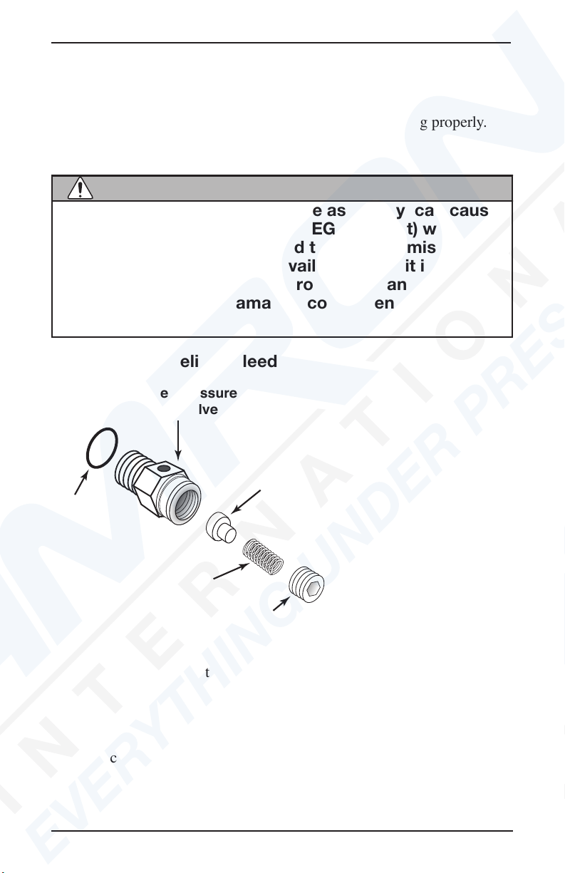
Components of the one way valve

Kirby Morgan Manifold Block
© Copyright ⅯⅯⅩⅢ Kirby Morgan Dive Systems, Inc. All rights reserved. Document # 130329001 3
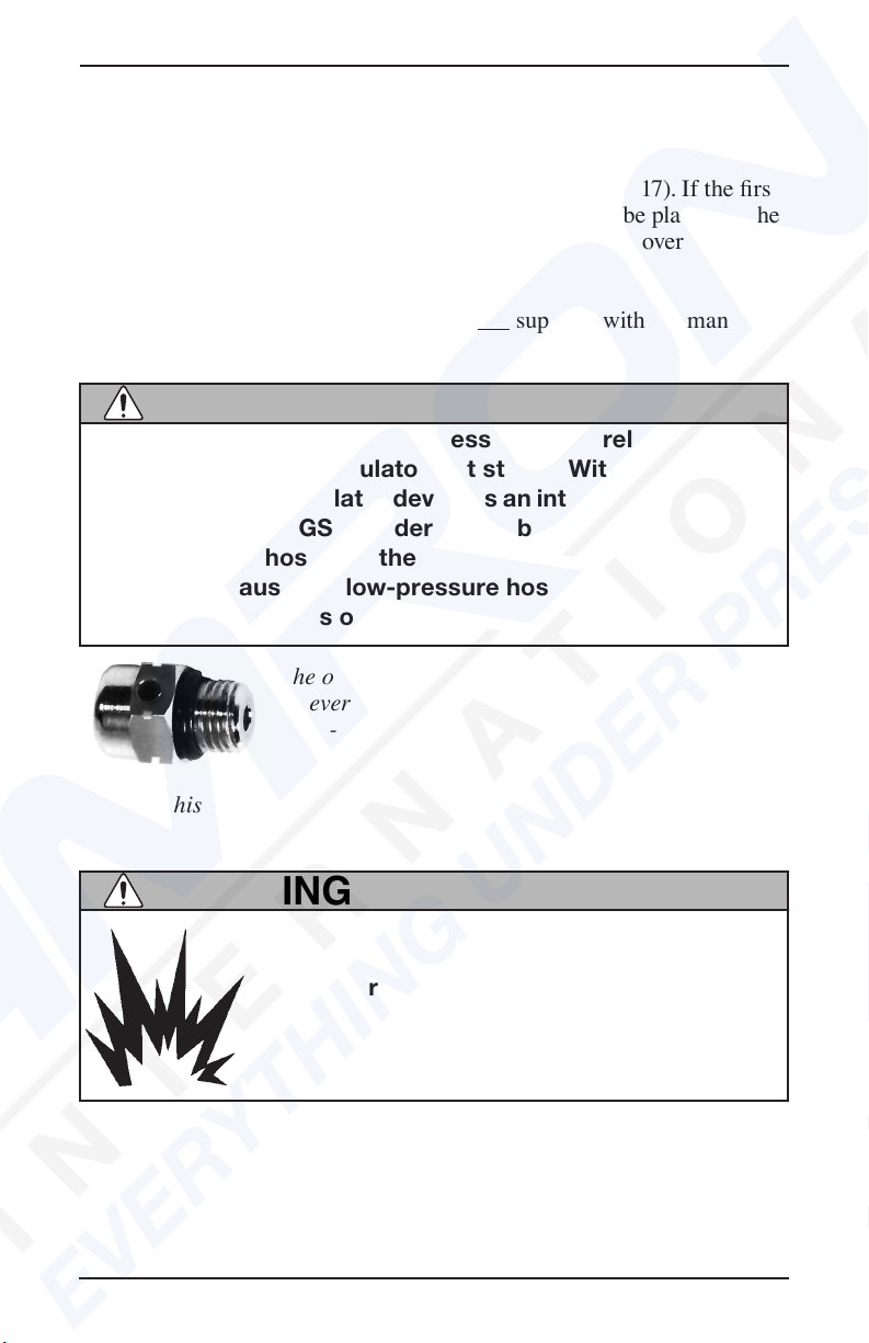
The one way valve is a very important component. It prevents the ow of
air out of the mask in the event of a sudden lowering of pressure in the
umbilical supply hose due to an accidental break in the hose or tting.
Not only would the emergency air be lost if the one way valve failed (con-
current with a hose or tting break) but the diver could be “squeezed,” a
very serious accident. Do not dive in the surface-supplied mode with-
out a one-way valve in the breathing system mounted on the diver’s
harness.
At a minimum, if you are doing surface-supplied diving, the following
systems and components must be in place and in proper working condi-
tion.
1) Air Supply: Either a low pressure compressor or high pressure air
bottles with a pressure reducing regulator capable of being manually
adjusted to 140 p.s.i over bottom pressure.
2) Dive Control System: An air management box to control the ow of
air to the diver or divers (such as the KMACS offered by KMDSI).
3) Divers Umbilical: Hose bundle consisting of air supply hose, pneu-
mofathometer hose (depth sensing), communications wire and rope as a
strength member.
4) Diver’s Manifold Block: A metal block that has a one way valve that
the umbilical attaches to, an emergency valve that the bail out system at-
taches to, and L.P. ports for attaching the mask hose, dry suit inators and
other accessories.
5) Bailout System: Consisting of a harness, bail out bottle, rst stage
regulator with over-pressure relief valve. This system connects to the
emergency valve on the divers manifold block assembly by a hose. Also
known as an Emergency Gas System.
6) Communications System: Provides hard wire communication be-
tween diver and top side.
Do not dive without a diver worn Emergency Gas System.
If the main gas supply is lost, you will have nothing to
breathe and may drown.
WARNING

Kirby Morgan Manifold Block
4 © Copyright ⅯⅯⅩⅢ Kirby Morgan Dive Systems, Inc. All rights reserved. Document # 130329001
Testing the Manifold Block
Prior to assembling a bailout system, the one way valve and emergency
valve should be tested for proper function.
Equipment Needed:
-Manifold Block
-Bailout bottle
-1st Stage regulator w/octopus and scuba reg
hose attached
-DCS system with an umbilical supply hose
-Bucket of water
Testing The One-Way Valve
1) With all the accessory holes plugged on the manifold block, attach the
SCUBA type regulator hose from a rst stage regulator that also has an
octopus attached, to the emergency valve on the manifold block assembly.
The octopus will be used for depressurization once the test is concluded.
2) Connect the rst stage to the bailout bottle, open the emergency valve
all the way, and pressurize the system.
3) Place the pressurized manifold block in a bucket of water and check
the one way valve for leaks. No air should leak through the one way valve
or from anywhere else on the manifold block assembly. If there is a leak,
the one way valve MUST be rebuilt or replaced.
4) As a secondary test, close the emergency valve trapping pressure inside
the manifold block assembly and relieve the pressure on the rst stage
using the octopus.
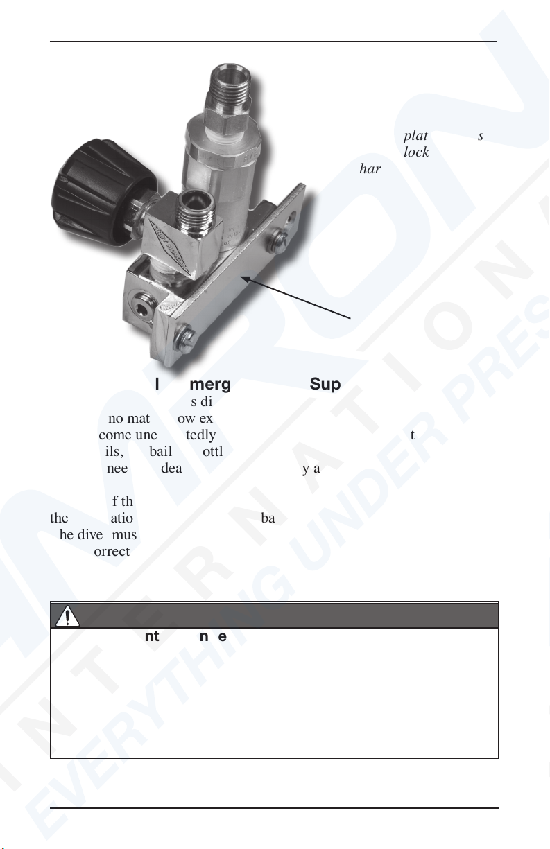
Emergency Gas
Supply Valve
On/Off Knob
Air supply
connects here
One-way valve
Low-pressure
port
Attachment plate
Low-pressure
ports (not in view)
Emergency gas
supply
connects here
Kirby Morgan Manifold Block
© Copyright ⅯⅯⅩⅢ Kirby Morgan Dive Systems, Inc. All rights reserved. Document # 130329001 5
Disconnect the hose from the emergency valve.
5) Quickly open the emergency valve by turning the knob. You should
hear the trapped air escaping through the emergency valve.
Testing The Emergency Valve
1) With all the accessory holes plugged on the manifold block, attach the
umbilical hose to the one way valve.
2) Make sure that the emergency valve is closed all the way and pressur-
ize the umbilical.
3) Place the pressurized manifold block in a bucket of water and check
the emergency valve for leaks. No air should leak through the emergency
valve or from anywhere else on the emergency valve assembly or mani-
fold block assembly. If there is a leak, the emergency valve MUST be
rebuilt or replaced.
4) Turn umbilical off and open the emergency valve to depressurize the
system and disconnect the hose.
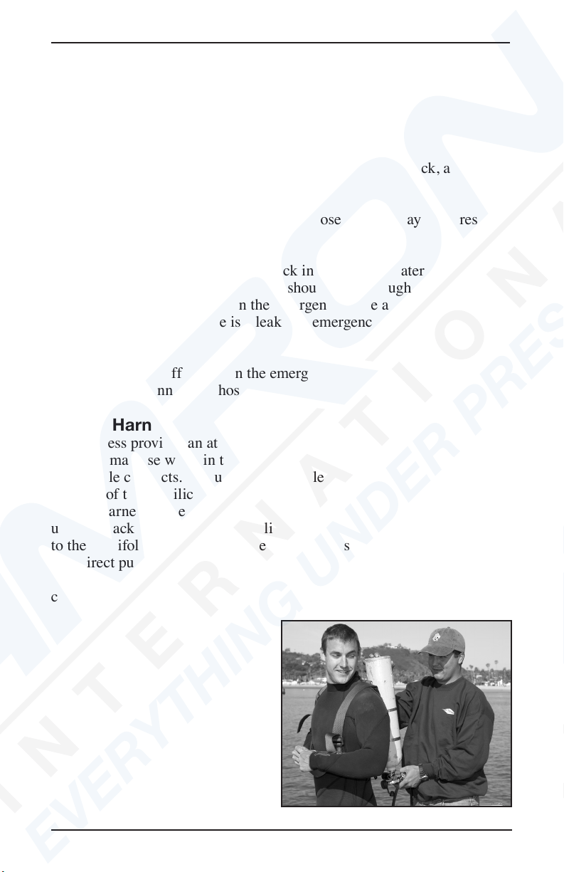
Diver’s Harness
The harness provides an attachment point for the manifold block, tools
the diver may use while in the water, and the ”D” ring where the umbili-
cal shackle connects. The umbilical shackle must connect to the strength
member of the umbilical. The manifold block attaches to the harness
and the harness is the primary attachment point for the diver’s umbilical
using a shackle. Arrange the umbilical so it attaches to the harness, then
to the manifold block on the harness. This helps eliminate the possibility
of a direct pull on the diver’s mask by topside. The harness may also be
used to lift an unconscious diver from the water and should be of sturdy
construction.
The diver must always wear a
bail-out bottle attached to a diver’s
harness for surface-supplied div-
ing.

Kirby Morgan Manifold Block
6 © Copyright ⅯⅯⅩⅢ Kirby Morgan Dive Systems, Inc. All rights reserved. Document # 130329001
Never dive without attaching the umbilical to some type of
harness or clip on the diver’s body. Never allow the umbili-
cal to pull on the mask directly or the diver could suffer
a neck injury, or the mask could be pulled off the diver’s
head.
WARNING
The diver’s umbilical must
always be connected by a snap
hook to the harness. Note the
submersible pressure gauge used
to monitor the bail-out supply.
Installing the Manifold Block on the Harness
The manifold block assembly is designed to be worn on the diver’s har-
ness. Most divers prefer to attach the manifold block to the right side
of the diver’s harness. The shackle which attaches the umbilical to the
harness “D” ring, is usually located on the left side. After attaching the
umbilical to the “D” ring on the left side of the harness, the umbilical is
normally routed behind the diver’s back to the manifold block.
To attach the manifold to the diver’s harness:
1) Remove one of the screws which holds the mounting plate on the
manifold block body and loosen the other screw to provide enough clear-
ance for a harness strap.
2) Swing the plate to one side and position the manifold block on the har-
ness.
3) Swing the plate back into the correct mounting position and thread the
screw through the plate and into the manifold body.
4) Tighten both screws until the harness is compressed between the mani-
fold and mounting plate holding the manifold block assembly in place.
Kirby Morgan Manifold Block
© Copyright ⅯⅯⅩⅢ Kirby Morgan Dive Systems, Inc. All rights reserved. Document # 130329001 7
Bail-Out Bottle (Emergency Gas Supply)
The diver should always dive with a bailout bottle when diving surface-
supplied, no matter how experienced or what the water depth. Should the
diver become unexpectedly entangled underwater, or if the top side air
supply fails, the bailout bottle must provide the few extra minutes of air
the diver needs to deal with the emergency and return to the surface.
The size of the bailout bottle should be determined by the water depth,
the penetration distance, or the probability of entanglement of the diver.
The diver must have sufcient air in the bail-out bottle to make an ascent
at the correct ascent rate and complete a precautionary decompression
stop or any required decompression.
The mounting plate secures
the manifold block to the
diver’s harness.
Rapid ascent is dangerous. It can lead to air embolism or
decompression sickness. Air/gas embolism can cause im-
mediate loss of consciousness and/or death. Even on a
no decompression dive, a rapid ascent may cause decom-
pression sickness. A diver must only make a rapid ascent
when he is in immediate danger of death by drowning or
asphyxiation.
DANGER
Mounting plate
Kirby Morgan Manifold Block
8 © Copyright ⅯⅯⅩⅢ Kirby Morgan Dive Systems, Inc. All rights reserved. Document # 130329001
The over-pressure relief valve should be installed
on every rst stage used for bailout. KMDSI Part
#200- 017
NOTE: This valve can be adjusted for various relief pressures.
Over-Pressure Relief Valve
The rst stage regulator must have at least two low pressure ports. One
port is used for the connector hose to the emergency valve and the second
is used to install an over-pressure relief valve (Part #200-017). If the rst
stage develops a leak, the full pressure of the tank could be placed on the
low pressure hose. This could cause the hose to burst. The over-pressure
relief valve will bleed off any leak.
Note that the over-pressure relief valve is not supplied with the manifold
block, but must be purchased separately.
Never dive without an over-pressurization relief valve in-
stalled on the EGS regulator (1st stage). Without the relief
valve if the EGS regulator develops an internal leak, the full
pressure of the EGS cylinder would be placed on the low-
pressure EGS hose and the Emergency Gas Supply Valve.
This could cause the low-pressure hose to burst resulting
in the complete loss of the EGS system.
WARNING
Ensure the relief/bleed valve is only in-
stalled in a low-pressure port of the rst
stage regulator. Installation in a high-
pressure port will lead to loss of EGS sup-
ply and possible serious personal injury
if the valve fails.
WARNING

Kirby Morgan Manifold Block
© Copyright ⅯⅯⅩⅢ Kirby Morgan Dive Systems, Inc. All rights reserved. Document # 130329001 9
Manifold Block Maintenance
Daily- A daily pre-dive inspection should be done prior to using the
Manifold Block. Carefully inspect the assembly for any sign of damage or
worn components.
Tools: open end wrenches, 1”, 11/16”, 9/16”, 5/8” and a 5/16 Allen wrench.
1) Check to ensure all the port plugs are installed and are tight.
2) Check to ensure the emergency gas supply whip is installed and tight,
on the emergency valve
3) Using a 5/8” open-end wrench, check to ensure the packing nut on
the emergency valve is snug. Note: do not over tighten. The valve handle
should turn freely. Check to ensure the packing nut does not turn -when a
light force is applied with the wrench.
4) Ensure the non-return valve and umbilical adapter are securely in
place.
5) Test the one way valve by sucking on the inlet tting with your lips. If
any air is drawn through the valves the valve must be rebuilt or replaced.
Post Dive Procedures
Daily post dive maintenance of the manifold block requires a brushing
with a solution of mild soapy water and a thorough rinsing with fresh
water. If hoses have been removed, ensure port plugs have been installed
and the umbilical connection has been capped or bagged.

Kirby Morgan Manifold Block
10 © Copyright ⅯⅯⅩⅢ Kirby Morgan Dive Systems, Inc. All rights reserved. Document # 130329001
Annual Overhaul of the Manifold Block Assembly.
The KMDSI manifold block should be rebuilt on an annual basis, or
when damage or corrosion is suspected or found.
Tools required: Table vise, 1” open end wrench (2ea), l l/16”, 5/8”, and
9/16” open end wrenches, a large at blade screwdriver, 5/16 Allen
wrench, 0-300 in Ibs. Torque wrench, soft nylon tooth brush, brass O-ring
pick and a solution of 50/5O white vinegar and water.
Parts required:
Manifold Repair Kit #325-095
Tools and Materials Needed:
1. Vise and clean rags
2. 9/16”, 5/8”, 11/16” and 1” (2) open end wrenches
3. 5/32” hex wrench
4. Large at blade screwdriver
5. Torque wrench, 0 - 300 inch pounds
6. Soft Nylon tooth brush
7. O-ring pick
8. White vinegar
Disassembly of Manifold Block
1) Remove the two at head screws from the manifold backing plate, and
remove the plate.
2) Remove all hoses and port plugs. Remove the O-ring from each plug
and place the plugs in a solution of 50/50 white vinegar and water.
3) Using a soft jaw vise or a rag wrapped around the manifold block to
keep from marring the nish, remove the one way valve from the mani-
fold block using the 1” wrench.
NOTE: The one way valve must be removed from the manifold block
before the emergency valve.
4) Using the 9/16 open-end wrench, loosen and remove the emergency
valve from the manifold block.
5) Place the manifold block body in a solution of vinegar and water, and
allow to soak while the other components are being disassembled. Using
the 1” wrench and the 9/16” wrench, loosen and remove the umbilical
adapter tting. Place it in the vinegar solution.
Kirby Morgan Manifold Block
© Copyright ⅯⅯⅩⅢ Kirby Morgan Dive Systems, Inc. All rights reserved. Document # 130329001 11
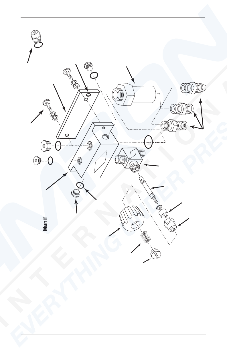
Lock
nut
Spring
Knob
Hose adapters
Valve
Stem
EGS Valve
Body
One-way
Valve
Low-pressure
plug
O-ring
Mounting
screw
Manifold Block Mounting
plate
Relief Valve for
EGS Regulator
Packing
Nut
Packing
Hole for
Shackle
Blow-apart drawing of
the manifold block
Kirby Morgan Manifold Block
12 © Copyright ⅯⅯⅩⅢ Kirby Morgan Dive Systems, Inc. All rights reserved. Document # 130329001
6) Carefully clean the manifold block body with a nylon toothbrush and
vinegar solution. Remove all traces of old lubricants, dirt and corrosion.
Rinse with fresh water and blow dry with compressed air or allow to air
dry. Using the nylon brush, clean the manifold plate and umbilical adapt-
er. Take special care to remove all the old Teon tape from the threads of
the umbilical adapter. Air or blow dry. Inspect all threaded ports for any
damage.
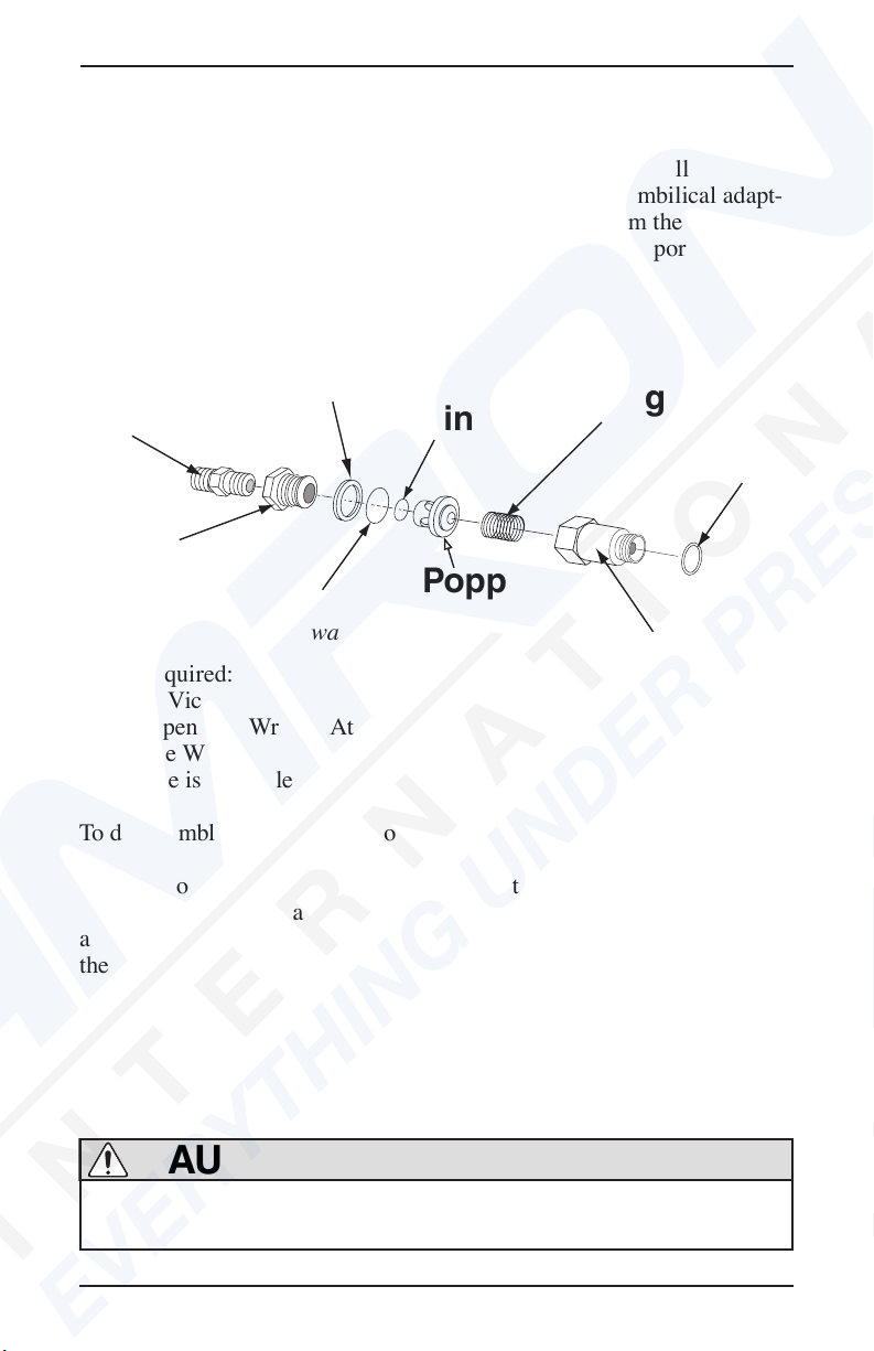
Adapter
Seat
Wiper
O-ring
O-ring
Poppet
Spring
Body
O-ring
Overhauling the One-Way Valve
Tools Required:
Soft Jaw Vice
1 inch Open End Wrench Attachment
on Torque Wrench
(If no vise is available use a backup 1 inch open end wrench)
To disassemble and inspect the one way valve assembly:
1) Use two wrenches or hold the hex part of the body in a soft jaw vise
while removing the seat with a wrench. As the seat is removed, the wiper
and the o-ring slide out in place in a groove on the seat. The poppet and
the poppet o-ring usually come out in the seat being followed by the
spring.
The only functional part remaining in the valve body is a non-moving,
pressed-in cage. The function of the cage is to contain the poppet during
high gas ows.
Do not use pliers on the main body of the one way valve.
You may damage the valve if pliers are used.
CAUTION
Components of the one-way valve.

Kirby Morgan Manifold Block
© Copyright ⅯⅯⅩⅢ Kirby Morgan Dive Systems, Inc. All rights reserved. Document # 130329001 13
2) Inspect the body interior for foreign matter of any type and clean, if
necessary. Clean in accordance with the KMDSI cleaning instructions.
If corrosion is present, clean using the acidic solution as outlined in the
KMDSI cleaning procedures.
3) Inspect the seat, wiper, o-ring, poppet o-ring and poppet for wear,
replace if necessary. Be sure each part is clean and all components are
lightly lubricated with the appropriate lubricant. A repair kit is available
for replacement parts, (Part #525-330). All o-rings should be replaced
during normal/annual overhauls.
4) Be careful to wipe the poppet and poppet o-ring thoroughly, remov-
ing nearly all silicone to prevent foreign materials from sticking to these
components.
5) Inspect the spring and clean or replace as needed.
Reassembly of the One Way Valve
1) Slide the new o-ring over the poppet.
2) Insert the new spring into the valve body, followed by the poppet.
3) Next, install the new o-ring and new wiper on the seat. Thread the seat
into the valve body.
4) Tighten the seat to 150 inch lbs. (17 newton meters) with a torque
wrench while holding the body in a soft jaw vice or wrench.
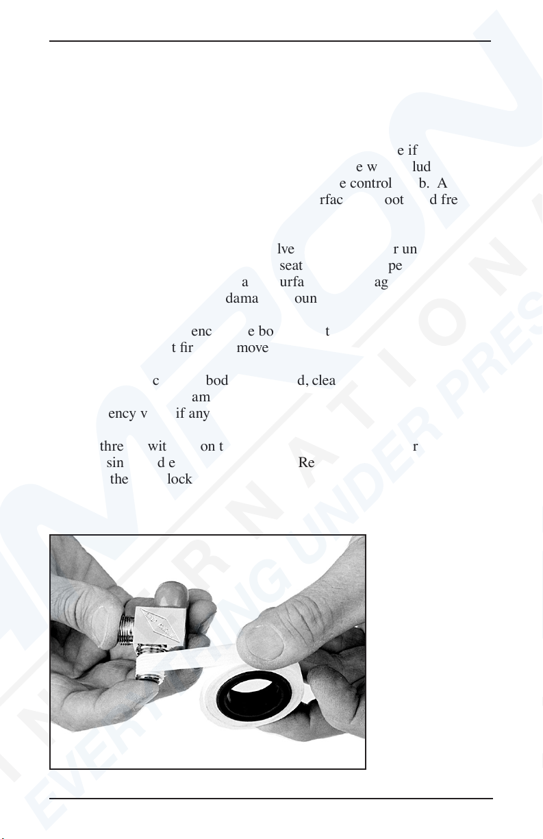
5) If the adapter has been removed, it must be cleaned and wrapped with
Teon tape.
NOTE: The one way valve must be installed in the manifold block after
the emergency valve.
Do not allow any Teon tape to cover the end of the adapt-
er, or to enter the one-way valve. Loose pieces of Teon
tape can interfere with the performance of the one-way
valve or the regulator and may block the diver’s air supply.
This could lead to death through suffocation.
WARNING
Kirby Morgan Manifold Block
14 © Copyright ⅯⅯⅩⅢ Kirby Morgan Dive Systems, Inc. All rights reserved. Document # 130329001
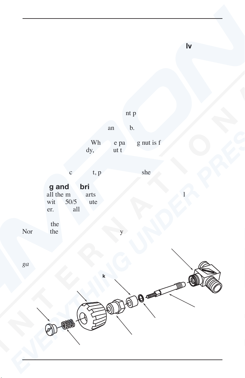
Valve Body
Valve Stem
Packing nut
Knob
Spring
Lock nut
Packing
Washer
6) Test the operation of the valve.
Disassembly of the Emergency Gas Supply Valve
Tools Required:
11/16 inch Open End Wrench
1 inch Open-end Wrench
Torque Wrench Attachments & Torque Wrench
3/8 inch Slotted Flat Blade Screwdriver
Soft Jaw Vice
Lubricant
Teon Tape
Normal minimum overhaul replacement parts: None
1) Remove the lock nut, spring, and knob.
2) Undo the packing nut. When the packing nut is free of the threads of
the emergency valve body, back out the stem until it is free of the emer-
gency valve body.
3) Remove the packing nut, packing, and washer from the stem.
Cleaning and Lubricating
1) Clean all the metal parts in a soap and water solution, followed by
cleaning with a 50/50 dilute solution of white vinegar/water. Rinse with
fresh water. Clean all parts.
2) Inspect the packing and washer for wear and replace if necessary.
Normally the packing will last a very long time and does not require
Components of the emergency
gas supply valve
Kirby Morgan Manifold Block
© Copyright ⅯⅯⅩⅢ Kirby Morgan Dive Systems, Inc. All rights reserved. Document # 130329001 15
replacement as long as the valve operates smoothly and does not leak. To
replace the packing place the packing nut in a vise and carefully work
the packing out with a small screw driver, taking care not to damage the
threads of the packing nut. Replace the washer.
3) Inspect the stem seat for unevenness or wear and replace if necessary.
It must also be replaced if the stem is bent. Damage will include dam-
aged threads, and/or rounded ats that engage the control knob. Also
inspect the shaft to ensure the conical seat surface is smooth and free of
corrosion or damage.
4) Check the seat in the emergency valve body for wear or unevenness,
galling and corrosion. To clean up the seat surface use a pencil eraser to
buff the surface. Inspect all threaded surfaces for damage. Replace the
emergency valve body if any damage is found.
5) To remove the emergency valve body from the side block the one way
valve assembly must rst be removed.
6) If the emergency valve body is removed, clean and inspect the pipe
thread and inspect for damaged threads, cracking, or distortion. Replace
the emergency valve if any damage is present.
Re-tape threads with Teon tape, 1 1/2 wraps starting two threads back.
Tighten using good engineering practice. Reinstall the emergency valve
body into the side block before installing the one way valve assembly.
Use only Teon
taped to seal the
emergency valve
in the manifold
block.

Kirby Morgan Manifold Block
16 © Copyright ⅯⅯⅩⅢ Kirby Morgan Dive Systems, Inc. All rights reserved. Document # 130329001
Reassembly of Emergency Valve
1) Lightly lubricate the stem threads in the body as well as the bonnet
threads.
2) Replace the washer and packing on the stem, then lightly lubricate the
stem shaft and threads.
3) Holding these components in place on the stem, screw the stem into
the emergency gas valve body.
4) Rotate the stem until it is seated all the way in then, back it out -1/2
turn.
5) T
hread the packing nut onto the emergency valve body. Run the nut in
and tighten slightly with a wrench.
6) Inspect the emergency gas valve knob for wear and damage. Ensure the
ats that engage the valve stem shaft are not rounded, cracked or damaged.
The valve knob should not have rotational play greater than 1/16th of a turn.
7) Place the emergency gas valve knob onto the stem and rotate the stem
all the way out, then back again. The rotation must be smooth. If “hard
spots” or unevenness are felt during the rotation, the stem may be bent
and could need replacement.
8) Tighten the packing nut with a torque wrench until moderate resis-
tance is felt when turning the knob. Torque to 50 inch pounds after seat-
ing.
9) Place the spring, and locknut onto the stem securing the knob.
10) Tighten the locknut until its top is ush with the top of the knob. The
assembly is now complete and ready for testing.
Do not use any sealant on pipe threads
on Kirby Morgan products other than
Teon tape or other approved sealants.
Other sealants may not be oxygen com-
patible and may lead to re or explosions
which may cause severe personal injury
or death.
WARNING
Kirby Morgan Manifold Block
© Copyright ⅯⅯⅩⅢ Kirby Morgan Dive Systems, Inc. All rights reserved. Document # 130329001 17
A leaking Emergency Gas Valve assembly can cause
the diver to exhaust his entire EGS (bailout) without
his knowledge. This may lead the diver to mistakenly
assume his EGS supply is available when it is not.
This could lead to panic or drowning in an emer-
gency. Any worn or damaged components must be
replaced.
WARNING
11) Test the valve by attaching it to an emergency air supply source. There
must be no leakage of gas past the stem or through the packing nut. Turn
on the bailout bottle and leave the supply on for several hours. There must
be no drop in pressure in the system if the valve is operating properly.
Overpressure Relief / Bleed Valve Overhaul Procedures
The relief/bleed valve should always be used on all Emergency Gas Sup-
ply (EGS/bail-out) rst stage regulators to prevent the hose from ruptur-
ing in the event the rst stage pressure creeps. The Kirby Morgan relief
body is made of stainless steel.
The basic components last a long time but the valve should be disas-
sembled, cleaned, and inspected at least once a year or whenever it fails
testing. The valve should be tested monthly. Cleaning and overhaul is
easily performed using a nylon toothbrush and a 50/50 solution of vinegar
O-ring
Over-Pressure
Relief Valve Body
Seat
Spring
Adjustment
Screw
Kirby Morgan Manifold Block
18 © Copyright ⅯⅯⅩⅢ Kirby Morgan Dive Systems, Inc. All rights reserved. Document # 130329001
and fresh water. Cleaning for 15 minutes in an ultrasonic sink, if avail-
able, with the 50/50 vinegar solution is highly recommended.
Repair parts are available. Normal replacement parts include the O-ring,
soft seat, spring, and hex nut. The O-ring should be replaced at least an-
nually. The other parts require replacement only if worn or damaged.
Tools Required.
Torque wrench
1/2” open-end wrench attachment for torque wrench
1/8” Allen wrench
Nylon toothbrush
Vinegar, Fresh water
Mild dish soap
Ultrasonic sink, if available
Magnifying glass
New valve body o-ring
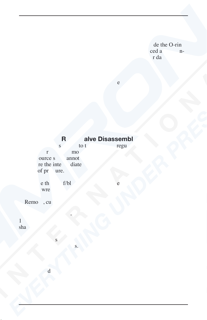
Overpressure Relief Valve Disassembly and Cleaning
1) Turn off the gas supply to the rst stage regulator, then bleed off any
remaining pressure. Remove the rst stage regulator from the air/breath-
ing gas source so it cannot be accidentally turned on, i.e., pressurized.
Make sure the intermediate pressure in the regulator hose is also fully
drained of pressure.
2) Remove the relief/bleed valve from the regulator body using the 1/2”
open-end wrench.
3) Remove, cut, and discard the relief/bleed valve body O-ring.
4) Using the 1/2” open-end wrench to hold the bleed/ relief body, use the
1/8” Allen wrench to remove the Allen head adjustment screw. Then,
shake out the spring and soft seat.
5) Place all parts in the 50/50 solution of vinegar and water and allow to
soak for 15 to 30 minutes. If using an ultrasonic sink, reduce time to 15
minutes.
6) Using the nylon toothbrush, brush all components to remove corrosion
and mineral deposits. Then, rinse with fresh water and blow or air dry.
7) Using the magnifying glass, carefully inspect all components for
excessive corrosion and/or damage. Replace the spring and/or adjustment

Kirby Morgan Manifold Block
© Copyright ⅯⅯⅩⅢ Kirby Morgan Dive Systems, Inc. All rights reserved. Document # 130329001 19
nut, if either part is excessively corroded or shows signs of wear and/or
damage.
Inspect the soft seat for nicks, cuts, and wear and replace if any damage
is found. Replace the entire assembly if any damage to the valve body is
present.
NOTE: A deep groove in the soft seat is normal. Replacement is only
necessary if the rubber seat is deteriorated, cut, and/or chipped.
Overpressure Relief Valve Reassembly
1) After cleaning, inspection and/or parts replacement, reassemble the
valve by installing the soft seat, spring, and adjustment nut. Screw the
adjustment nut down until it is approximately 1/2 thread from being ush
with the top of the valve body.
2) Lightly lubricate a new body O-ring, then install on the valve body.
3) Test the relief/bleed valve according to the test procedure below.
Overpressure Relief Valve Lift Check/Setting
Tools required:
Adjustable rst stage scuba regulator or controlled adjustable pressure
source
Intermediate pressure test gauge
Torque wrench
1/2” open-end wrench adapter for torque wrench
1/8” Allen wrench
HP air source {SCUBA tank) with at least 500 p.s.i.g. (34.4 bar).
Mild dish soap
The purpose of lift checking the relief/bleed valve is to ensure it oper-
ates properly, allowing excess pressure to escape in the event the rst stage
develops a slight leak. Without the relief/bleed valve, high-pressure gas will
continue to increase until the emergency supply hose ruptures, possibly caus-
ing injury and a complete loss of the Emergency Gas System (EGS).
This procedure explains the steps necessary for readjusting the relief/bleed
valve after it is cleaned, overhauled or any time the valve is tested.
NOTE: The relief/bleed valve is lift checked and/or adjusted using an
adjustable rst stage regulator, equipped with a low-pressure test gauge,
which is used for adjusting the intermediate pressure of scuba regulators.
Kirby Morgan Manifold Block
20 © Copyright ⅯⅯⅩⅢ Kirby Morgan Dive Systems, Inc. All rights reserved. Document # 130329001
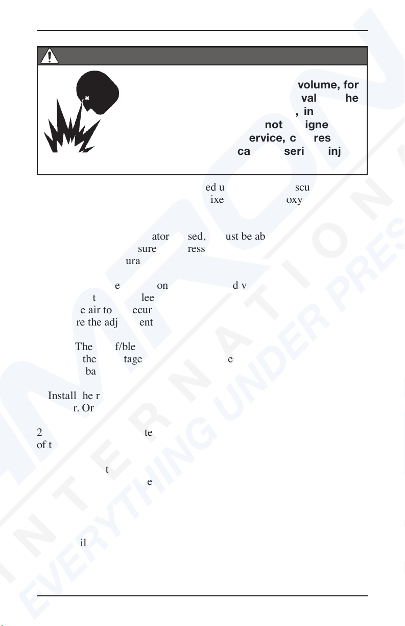
Do not use oxygen, or mixed gas contain-
ing more than 23% oxygen by volume, for
lift checking the relief/bleed valve. The
use of oxygen, or mixed gas, in a high-
pressure supply system not designed and
cleaned for oxygen service, can result in
a re or explosion causing serious injury
or death.
DANGER
The check/adjustment can be performed using a standard scuba test stand,
or a gas control console, using air or mixed gas with an oxygen content
below 23% by volume.
If a rst stage scuba regulator is used, it must be able to be adjusted to
the desired lifting pressure. The pressure gauge should be compared to a
gauge of known accuracy.
NOTE: If the Allen screw on the relief/bleed valve hex nut is rotated too
far, too fast, the relief/bleed valve will pop open. This could possibly
require the air to be secured at the cylinder or supply source to reset the
seat before the adjustment can be accomplished.
NOTE: The relief/bleed valve can be installed in any rst stage regulator,
providing the rst stage has an intermediate setting of 135 - 165 p.s.i.g.
(9.3 – 11.4 bar).
1) Install the relief valve in a low-pressure port on an adjustable 1st stage
regulator. Or install on the scuba test stand.
2) Install the intermediate pressure gauge in one of the low-pressure ports
of the rst stage regulator.
3) Install the 1st stage regulator on the cylinder. Ensure the relief valve
and intermediate pressure gauge are attached to low-pressure ports.
4) Wet the relief valve with soapy water to help indicate gas ow.
5) Slowly bring up air pressure while watching the intermediate pressure
gauge until the pressure gauge indicates 180- 200 p.s.i.g. (12.40-13.78
bar). If the relief valve starts venting at a pressure below 180- 200 p.s.i.g.
(12.40-13.78 bar), secure the air supply and adjust the adjustment screw
This manual suits for next models
2
Table of contents
Other Dive System Diving Instrument manuals


