Aeris ATMOS 2 User manual

ATMOS 2
DIVE COMPUTER
OWNER'S GUIDE
O
R

2
LIMITED TWO-YEAR WARRANTY
For details, refer to the Product Warranty Registration Card provided.
COPYRIGHT NOTICE
This owners guide is copyrighted, all rights are reserved. It may not, in whole or in part, e copied, photocopied,
reproduced, translated, or reduced to any electronic medium or machine reada le form without prior consent in writ-
ing from AERIS / 2002 Design.
ATMOS 2 Owner's Guide, Doc. No. 12-7129
© 2002 Design 2001
San Leandro, Ca. USA 94577
TRADEMARK NOTICE
AERIS, the AERIS logo, ATMOS 2, and the ATMOS 2 logo are all registered and unregistered trademarks of
AERIS. All rights are reserved.
PATENT NOTICE
U.S. Patents have een issued, or applied for, to protect the following design features:
Dive Time Remaining (U.S. Patent no. 4,586,136), Data Sensing and Processing Device (U.S. Patent no.
4,882,678), and Ascent Rate Indicator (U.S. Patent no. 5,156,055). User Seta le Display (U.S. Patent no.
5,845,235) is owned y Suunto Oy (Finland).
DECOMPRESSION MODEL
The programs within the ATMOS 2 simulate the a sorption of nitrogen into the ody y using a mathematical
model. This model is merely a way to apply a limited set of data to a large range of experiences. The ATMOS 2
dive computer model is ased upon the latest research and experiments in decompression theory. Still, using the
ATMOS 2, just as using the U.S. Navy (or other) No Decom ression Tables, is no guarantee of avoiding de-
com ression sickness, i.e. the bends. Every divers physiology is different, and can even vary from day to day.
No machine can predict how your ody will react to a particular dive profile.

3
CONTENTS
WARRANTY ................................................................................................................................................................. 2
NOTICES ..................................................................................................................................................................... 2
DECOMPRESSION MODEL ....................................................................................................................................... 2
FEATURES AND DISPLAYS ............................................................................................. 7
CONTROL BUTTONS ................................................................................................................................................. 9
BAR GRAPHS ............................................................................................................................................................. 9
Nitrogen Bar Graph ................................................................................................................................................ 9
Oxygen (O2) Bar Graph ........................................................................................................................................ 10
Variable Ascent Rate ndicator ............................................................................................................................. 10
INFORMATIONAL DISPLAYS ................................................................................................................................... 11
Depth Displays ..................................................................................................................................................... 11
Time and Date Displays ....................................................................................................................................... 11
Temperature Display ............................................................................................................................................. 12
AUDIBLE ALARM ...................................................................................................................................................... 13
LED WARNING INDICATOR ..................................................................................................................................... 14
BACKLIGHT .............................................................................................................................................................. 14
POWER SUPPLY ...................................................................................................................................................... 15
Battery ndicator ................................................................................................................................................... 15
Low Battery Condition .......................................................................................................................................... 16
FO2 MODE ................................................................................................................................................................. 17
FO2 50% Default .................................................................................................................................................. 18
DIVE TIME REMAINING ........................................................................................................................................... 19
ACTIVATION AND SETUP ............................................................................................... 23
ACTIVATION .............................................................................................................................................................. 24
SURFACE MODE ...................................................................................................................................................... 25
SET MODES .............................................................................................................................................................. 2
ENTER NG SETT NGS -SET MODE #1 ............................................................................................................... 27
ENTER NG SETT NGS -SET MODE #2 ............................................................................................................... 31

4
PRE DIVE PLAN MODE .................................................................................................. 45
DIVE PLANNER ........................................................................................................................................................ 4
DIVE MODES ................................................................................................................... 49
DIVE MODE BAR GRAPHS ...................................................................................................................................... 50
CONTROL OF DISPLAYS ......................................................................................................................................... 50
NO DECOMPRESSION DIVE MODE ....................................................................................................................... 51
DECOMPRESSION DIVE MODE ............................................................................................................................. 52
VIOLATION MODES .................................................................................................................................................. 5
Conditional Violation Mode .................................................................................................................................. 57
Delayed Violation Modes ..................................................................................................................................... 58
mmediate Violation Mode and Gauge Mode ...................................................................................................... 59
HIGH PO2 DIVE MODE ............................................................................................................................................. 1
HIGH OXYGEN ACCUMULATION ............................................................................................................................ 2
USER SET DIGITAL GAUGE MODE ........................................................................................................................ 4
POST DIVE MODES ........................................................................................................ 65
POST DIVE SURFACE MODE ..................................................................................................................................
TRANSITION PERIOD ..............................................................................................................................................
AFTER THE TRANSITION PERIOD (THE FIRST 2 HOURS) .................................................................................. 8
To access the Dive Planner (Plan Mode) ............................................................................................................. 68
To access the Time to Fly Countdown ................................................................................................................. 69
To access the Time to Desaturate Countdown .................................................................................................... 70
LOG MODE .......................................................................................................................................................... 70
AFTER THE FIRST 2 HOURS ................................................................................................................................... 73
DOWNLOADING DATA TO A PC .............................................................................................................................. 74
RESET (CLEAR) ............................................................................................................. 75
SIMULATOR (DEMO) MODE .......................................................................................... 77
CONTENTS (con inued)
5
CARE, MAINTENANCE, AND SERVICE......................................................................... 83
CARE AND CLEANING ............................................................................................................................................. 84
INSPECTIONS AND SERVICE ................................................................................................................................. 85
BATTERY REPLACEMENT ...................................................................................................................................... 8
REFERENCE ................................................................................................................... 91
DECOMPRESSION MODEL ..................................................................................................................................... 92
TISSUE COMPARTMENT CONTROL ...................................................................................................................... 92
NO DECOMPRESSION LIMITS ................................................................................................................................ 93
OXYGEN EXPOSURE LIMITS ................................................................................................................................. 94
ALTITUDE SAMPLING/COMPENSATION ................................................................................................................ 95
FLYING AFTER DIVING ............................................................................................................................................ 9
SPECIFICATIONS ........................................................................................................... 98
GLOSSARY ................................................................................................................... 103
SERVICE RECORD ....................................................................................................... 107
CONTENTS (con inued)
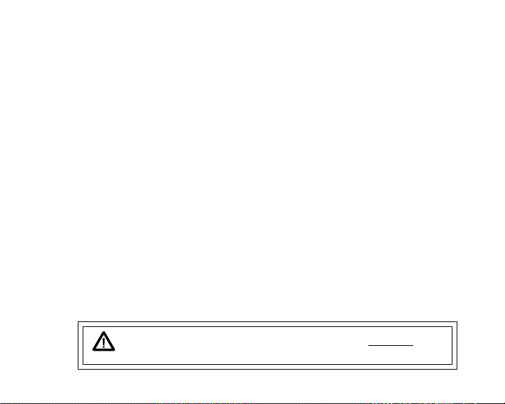
Pay special a en ion o i ems marked wi h his Warning symbol.

6
The ATMOS 2 is not intended fo use by milita y o comme cial dive s.
The ATMOS 2 is intended fo use by ec eational dive s who have successfully completed a
nationally ecognized cou se in scuba diving, and diving with en iched nit ogen-oxygen
(nit ox) mixtu es.
It must not be used by unt ained pe sons who may not have knowledge of the potential
isks and haza ds of scuba diving, and diving with nit ox.
You must obtain scuba ce tification, and ce tification in diving with nit ox befo e using the
ATMOS 2, if you have not al eady done so.
It is NOT fo use by milita y and comme cial dive s.
It should NOT be utilized fo any competitive, o epetitive squa e wave o unplanned de-
comp ession diving, it is intended solely fo ec eational use and multilevel diving.
As with all unde wate life suppo t equipment, imp ope use o misuse of this p oduct can
cause se ious inju y o death.
Conduct you dives in such a manne so as to insu e that you continuously check the
compute 's p ope function.
If you do not fully unde stand how to use this dive compute , o if you have any questions,
you should seek inst uction in its use f om you autho ized AERIS deale befo e you utilize
this p oduct.
Neve pa ticipate in sha ing o swapping of a dive compute . Doing so may esult in inju y
o death.
If you exceed ce tain limits, the ATMOS 2 will not be able to tell you how to get safely back
to the su face. These situations exceed tested limits and can esult in loss of some ATMOS
2 functions fo 24 hou s afte the dive in which a Violation occu ed.
The ATMOS 2 ente s Immediate Violation Mode when a situation totally exceeds its capacity
to p edict an ascent p ocedu e. These dives ep esent g oss excu sions into decomp es-
sion that a e beyond the bounda ies and spi it of the ATMOS 2 design. If you a e following
these dive p ofiles, AERIS advises you not to use an ATMOS 2 dive compute .
WARNINGS AND SAFETY RECOMMENDATIONS

7
FEATURES and DISPLAYS

8
WELCOME TO AERIS !
AND
THANK YOU FOR CHOOSING THE ATMOS 2 !
Your ATMOS 2 presents the information that you need before, during, and after your air (or nitrox)
dives using a combination of easy to read disp ays and identification icons. It can a so be set to oper-
ate simp y as a digita depth gauge/timer. This instructiona guide is intended to he p you become fa-
mi iar with the functions and features avai ab e and show you examp es of disp ays that you cou d ex-
pect to see in the various operationa modes. Re ax and read through the comp ete owner's guide.
Remember that the ru es you earned in your basic scuba certification course(s) sti app y to the div-
ing you wi do whi e using a dive computer - some wi become even more important. Techno ogy is
no substitute for common sense, and a dive computer on y provides the person using it with data, not
the know edge to use it.
Since the ATMOS 2 can be used when diving with either Air or Nitrox, the term Breathing Gas is
used in this manua .
Breathing Gas is the gaseous mixture breathed during a dive.
Air is a breathing gas that contains approximate y 21% oxygen and 79% nitrogen (nature's com-
mon nitrogen-oxygen mixture).
Nitrox is a nitrogen-oxygen breathing gas that contains a higher fraction of oxygen (22 to 50%)
than air.

9
CONTROL BUTTONS
The two Contro Buttons a ow you to se ect disp ay options, access specific information when you
want to see it, and activate the Back ight.
The Front button is named Advance (Fig. 1a) and the Side button Select (Fig. 1b).
BAR GRAPHS
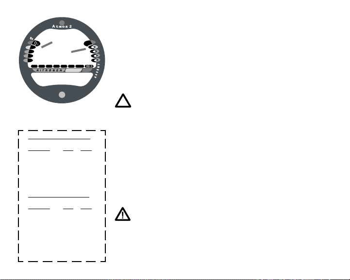
Ni rogen Bar Graph
The Nitrogen Bar Graph (Fig. 1c) represents tissue oading of nitrogen, showing your re ative No De-
compression or Decompression status. As your Depth and E apsed Dive Time increase, segments
wi add to the Graph, and as you Ascend to sha ower depths, the Bar Graph wi begin to recede, in-
dicating that additiona No Decompression Time is a owed for mu ti eve diving.
The Nitrogen Bar Graph monitors 12 different nitrogen compart-
ments simu taneous y and disp ays the one that is in contro of your
dive. It is divided into a green No Decompression (norma ) zone, a
ye ow Caution zone (a so No Decompression), and a red Decom-
pression (danger) zone.
Whi e you cannot provide a guarantee against the occurrence of de-
compression sickness, you may choose your own persona zone of
caution based upon age, physique, excessive weight, etc., to reduce
the statistica risk.
Fig. 1 - Buttons and NiBG
ab
c
10
Oxygen (O2) Accumula ion Bar Graph
The O2 Bar Graph (Fig. 2a) represents Oxygen Loading, your re a-
tive oxygen to erance dosage (OTU), showing the maximum of either
per dive accumu ated Oxygen, or 24 hour period accumu ated Oxy-
gen. As your accumu ation increases during the dive, segments wi
add to the Bar Graph, and as oading decreases, it wi begin to re-
cede, indicating that additiona exposure is a owed.
NOTE: Displays associa ed wi h Oxygen and he O2
Bar Graph will only appear if FO2 has been se a a
value o her han 'Air' (e.g., a numerical value).
Variable Ascen Ra e Indica or
The Variab e Ascent Rate Indicator (Fig. 2b) provides a visua repre-
sentation of Ascent Speed (i.e., an ascent speedometer). Green is a
'norma ' rate, ye ow a 'caution' rate, and red is 'Too Fast'. The seg-
ments of the Variab e Ascent Rate Indicator represent 2 sets of
speeds which change at a reference depth of 60 feet (18 meters). Re-
fer to the chart for segment va ues.
WARNING: A dep hs grea er han 60 fee (18
me ers), Ascen Ra es should no exceed 60 fee per
minu e (18 mpm). A dep hs of 60 fee (18 me ers)
and shallower, Ascen Ra es should no exceed 30
fee per minu e (9 me ers per minu e).
Fig. 2 - O2BG & VAR
Variable Ascent Rate ndicator
Deeper than 60 feet (18 m)
Segments Ascent Rate =
Displayed FPM MPM
0 0-20 0 - 6
1 21-30 6.5-9
2 31- 0 9.5-12
3 1-50 12.5-15
51-60 15.5-18
5 >60 >18
60 feet (18 m) & Shallower
Segments Ascent Rate =
Displayed FPM MPM
0 0-10 0 - 3
1 11-15 3.5- .5
2 16-20 5-6
3 21-25 6.5-7.5
26-30 8-9
5 >30 >9
a
b

11
INFORMATIONAL DISPLAYS
Each numeric and graphic display represents a unique piece of information. It is imperative
that you understand the formats, ranges, and values of the information represented to avoid
any possible misunderstanding that could result in error.
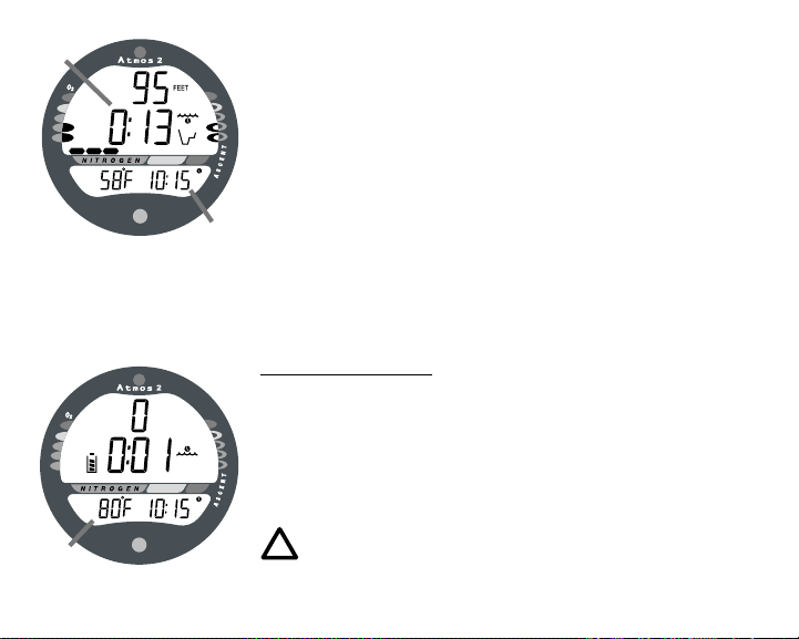
Dep h Displays
During a dive, the Current Depth disp ay (Fig. 3a), indicates depths from 0 to 330 feet (99.9
meters) in 1 foot (.1 meter) increments. The Ma imum Depth reached during that dive wi be dis-
p ayed in the ower window of the disp ay (Fig. 3b).
When the unit is set to operate as a digita depth gauge/timer (referred to as User Set Gauge
Mode), the Depth Disp ay range is 'extended' to 399 feet (120 meters). At depths greater than
99.9 meters, it wi indicate metric va ues in increments of 1 meter.
During a Decompression Dive, the required Ceiling Stop Depth is
disp ayed in the ower window. Maximum Depth can then be viewed
by pressing the Advance (Front) button.
Time and Da e Displays
Time displays are shown in hour:minute format (i.e., 1:22 represents
1 hour and 22 minutes, not 122 minutes!). The co on that separates
hours and minutes b inks once per second when the disp ay is indicat-
ing rea time (e.g., E apsed Dive Time), and is so id (non-b inking)
when times are ca cu ated projections (e.g., Time to F y).
Fig. 3 - Depth Displays
a
b
12
Due to the importance of the information it presents, the Main Time
disp ay (Fig. 4a) is configured with the argest segments of the LCD.
A second time display (Fig. 4b) is ocated in the ower window.
Both disp ays are identified by a c ock icon.
Time of Day can be set for 12 hour format (Am/Pm) or 24 hour
format.
Date is disp ayed in the ower screen on y to identify dive data whi e
it is viewed in the Log Mode.
When Units of Measure are set for 'Imperia ', the Month appears
to the eft of Day. When set for Metric, the Month appears to the
right of Day.
Tempera ure Display
Ambient Temperature is disp ayed in the ower window (Fig. 5a)
whi e in the Surface Mode and can be viewed as part of an A ternate
Disp ay when the Advance (Front) button is pressed whi e in a dive
mode. If the Temperature exceeds a va ue of '99', 2 dashes ( - - ) wi
be disp ayed on the screen unti the unit's temperature decreases to
'99'.
NOTE: The Informa ional Displays are described in
de ail as he various opera ing modes hey appear
in are presen ed hroughou his manual.
Fig. 4 - Time Displays
Fig. 5 - Temperature
a
b
a

13
AUDIBLE ALARM
When warning situations activate the A arm, the unit wi emit a continuous tone for 30 seconds, or
unti the situation is corrected, or it is acknow edged by pressing the Advance (Front) button for 2
seconds. If acknow edged by the user and the situation corrected, the A arm wi sound again upon
reentry into the warning situation, or entry into another type of warning situation.
Warning situations that will sound the Alarm, if it is turned ON (a user setting), include -
Entry into Decompression Mode
PO2 => than the Max PO2 A arm (a user setting), or => 1.60 ATA.
Descent deeper than the Max Depth A arm (a user setting).
Nitrogen Bar Graph A arm (a user setting).
Dive Time Remaining A arm (a user setting).
E apsed Dive Time A arm (a user setting).
O2 Accumu ation => a owab e per dive imit, or imit for a 24 hour period.
Ascending above a required Decompression stop depth for < 5 min. (Conditiona Vio ation).
Ascent rate exceeds 60 fpm (18 mpm) if > 60 ft (18 m), or 30 fpm (9 mpm) if <= 60 ft (18 m).
During the following situations, the 30 second continuous tone will be followed by a 5 second
steady beep that will not turn off when acknowledged, even if it was user Set OFF -
Ascending above a required Decompression stop depth for more > 5 min. (De ayed Vio ation).
Decompression requires a cei ing stop depth => 70 FT (18 M).
Being on the surface for 5 minutes after a Conditiona Vio ation (Permanent Vio ation).
A single short beep (which cannot be disabled) is emitted - after the Diagnostic check, upon auto-
matic return to Surface Mode from Simu ator Mode, upon comp etion of a fast battery change with
ca cu ations/settings saved, and upon change from De ayed to Fu Vio ation after that dive.

14
LED WARNING INDICATOR
The red LED Warning Light ocated on the upper portion of the mod-
u e (Fig. 6) is synchronized with the Audib e A arm and wi indicate
an A arm when the unit emits a tone.
The LED wi be OFF when the A arm is acknow edged, or Set OFF
(a user setting).
BACKLIGHT
To activate the Backlight whi e in the Surface Mode or during a
dive-
press and re ease the Se ect (Side) button.
The screens wi be i uminated for 3, 5, or 7 seconds (a user set-
ting). Press and re ease the button again to activate as desired.
The Back ight i uminates both the upper and ower screens.
The Back ight does not operate during a Low Battery condition.
NOTE: AERIS recommends ha you always carry
primary and backup dive ligh s when conduc ing
dives ha could include low ligh si ua ions.
Fig. 6 - LED Warning

15
POWER SUPPLY
The ATMOS 2 uti izes one (1) type CR 2450 Lithium 3 vo t ce
that shou d provide approximate y 300 hours of continuous, or 50
activation periods, of operation.
If you conduct 1 dive each time the unit is activated, you shou d
obtain approximate y 50 dives.
If you conduct 3 dives each time the unit is activated, you shou d
obtain approximate y 150 dives.
Ba ery Indica or
A Battery Indicator provides an indication of battery condition.
When power is sufficient for norma unit operation, the Indicator
(icon) wi be disp ayed during Surface Mode (Fig. 7a).
The Indicator wi not be disp ayed during dive modes.
When a Low Battery Condition is sensed, the Indicator wi f ash.
(continued on page 16)
Fig. 7 - Battery ndicator
a
16
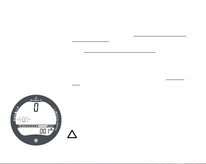
Low Ba ery Condi ion
Vo tage eve is checked upon activation and every 10 minutes dur-
ing operation.
If a Low Battery Condition exists when the unit is activated (by
pressing the button), the Battery icon wi appear f ashing once per
second for 5 seconds (Fig. 8) fo owed by shutdown of the unit.
If the button is not pressed to activate the unit prior to a dive, and
a Low Battery Condition exists, the Low Battery icon wi appear
f ashing as a warning upon descent past 4 feet (1.2 meters). No
other information wi be disp ayed.
If the unit did not disp ay the Low Battery icon 'prior to' entering
the Dive Mode, and a Low Battery Condition occurs during the
dive, there wi be sufficient battery power to maintain unit opera-
tion for the remainder of 'that dive'. The Low Battery icon wi
appear upon surfacing when Surface Mode is disp ayed.
When the Battery is removed, nitrogen and oxygen ca cu ations for
repetitive dives are reset to zero after 8 seconds. A so, settings such
as Time, Date, and FO2 must be reset. If a new battery can be in-
serted within 8 seconds, the ca cu ations and settings wi be retained.
NOTE: Ba ery change procedures are described
on page 86 of his manual.
Fig. 8 - Low Battery
17
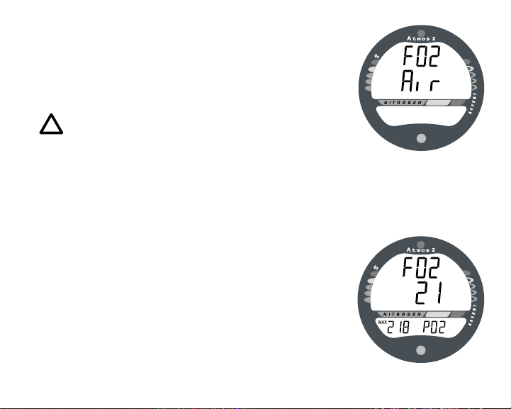
FO2 MODE
After Activation, the ATMOS 2 wi operate as an Air computer
without disp aying information associated with oxygen ca cu ations,
un ess it is set for a percentage of oxygen (FO2) other than Air (nu-
merica va ue between 21 and 50 %).
NOTE: Se ing FO2 is described on Page 27.
When set with an FO2 value of 'Air' (Fig. 9), the ATMOS 2 wi
perform ca cu ations the same as if FO2 were set for 21% oxygen, in-
terna y accounting for oxygen oading for any subsequent Nitrox
dives. However, oxygen re ated disp ays, warnings, and the O2 bar
graph wi not appear on the disp ay for that dive, or subsequent
dives, un ess FO2 is set for a numerica va ue (21 - 50).
Once a dive is made with the unit set as a nitrox computer (FO2 set
for a numerica va ue), the unit cannot be programmed to operate as
an 'Air' computer unti 24 hours after the ast dive. 'Air' wi not be
disp ayed as an option in the FO2 Mode. However, you can set FO2
for 21% for use with Air.
When FO2 is set at a value of 21% (Fig. 10), the unit wi remain
set at 21% for subsequent nitrox dives unti FO2 is set to a higher
va ue, or unti it automatica y turns off and is reactivated.
Fig. 9 - FO2 Air
Fig. 10 - FO2 of 21%

18
WARNING: The percen age of oxygen (FO2) in he
ni rox mix being used mus be se 'before each'
ni rox dive, unless he FO2 50% Defaul fea ure has
been urned OFF.
FO2 50% Defaul
If the Default is set to ON and FO2 is set to a va ue 'greater than
21%', the FO2 set point va ue wi automatica y revert to 50% 10
minutes after that dive (Fig. 11). The Maximum Depth that can be
achieved with a PO2 of 1.60 ATA wi a so be disp ayed.
FO2 must therefore be reset for each repetitive nitrox dive, or the
va ue wi automatica y 'defau t' to 50(%) and the dives wi be
ca cu ated based on 50% O2 (50% nitrogen) for oxygen ca cu a-
tions and 21% O2 (79% nitrogen) for nitrogen ca cu ations.
WARNING: If you surface for grea er han 10 min-
u es during a dive, a subsequen descen will be
considered a new dive and FO2 mus be rese .
If the Default is set to OFF, the FO2 va ue for repetitive dives re-
mains the same (Fig. 12) unti the set point is manua y changed.
WARNING: Even if he Defaul is se o OFF, he
FO2 se poin should be 'verified' o ma ch he FO2
in he ni rox mix being used before each ni rox dive.
Fig. 11 - FO2 Default ON
Fig. 12 - FO2 Default OFF

19
DIVE TIME REMAINING
One of the most important pieces of information on Aeris dive com-
puters is the 'Dive Time Remaining numeric disp ay'. The dive com-
puter constant y monitors no decompression status and oxygen expo-
sure.
The Dive Time Remaining* display will indicate the time that is
more critical for you at that particular moment (i.e.; whichever
time is the least amount available). The specific time being dis-
p ayed is identified by the No Decompression Dive Time icon, or the
O2 Time icon.
(* This unique feature has been granted U.S. Patent No. 4,586,136.
No Decompression Dive Time Remaining
No Decompression Dive Time Remaining is the maximum amount
of time that you can stay at your present depth before entering a de-
compression situation. It is ca cu ated based on the amount of nitro-
gen absorbed by hypothetica tissue compartments. The rates each of
these compartments absorb and re ease nitrogen is mathematica y
mode ed and compared against a maximum a owab e nitrogen eve .
Whichever one is c osest to this maximum eve is the contro ing
compartment for that depth. Its resu ting va ue wi be disp ayed nu-
merica y (Fig. 13a) a ong with the No Decompression Dive icon and
graphica y as the Nitrogen Bar Graph (Fig. 13b).
Fig. 13 - No Decompression
Dive Time Remaining
a
b

20
As you ascend from depth fo owing a dive that has approached the
no decompression imit, the Nitrogen Bar Graph wi recede as con-
tro shifts to s ower compartments. This is a feature of the decom-
pression mode that is the basis for mu ti eve diving, one of the most
important advantages that Aeris dive computers offer.
The no decompression a gorithm is based upon Ha danes theory us-
ing maximum a owab e nitrogen eve s deve oped by Merri Spen-
cer. Repetitive diving contro is based upon experiments designed
and conducted by Dr. Ray Rogers and Dr. Michae Powe in 1987.
Diving Science and Techno ogy® (DSAT), a corporate affi iate of
PADI®, commissioned these experiments.
Oxygen Accumula ion Time Remaining
Oxygen accumu ation (exposure) during a dive, or 24 hour period,
appears graphica y as the Oxygen Accumu ation (O2) Bar Graph
(Fig. 14a). As time remaining before reaching the oxygen exposure
imit decreases, segments are added to the O2 Bar Graph.
When the amount of time remaining before reaching the oxygen imit
becomes ess than the No Decompression Dive Time Remaining, ca -
cu ations for that depth wi be contro ed by oxygen. Oxygen Time
Remaining wi then appear as the main numeric time disp ay (Fig.
14b) as signified by the O2 Time icon appearing on the disp ay. As
oxygen accumu ation continues to increase, the O2 Bar Graph wi
enter the ye ow Caution Zone.
Fig. 14 - O2 Accumulation
Dive Time Remaining
a
b
Other manuals for ATMOS 2
1
Other Aeris Diving Instrument manuals


