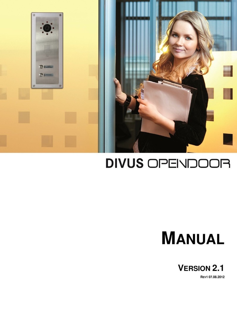
Divus VIDEOPHONE - BOX User manual

VIDEOPHONE -BOX
MANUAL
VERSION 1.1
REV107.08.2012

www.divus.eu
VIDEOPHONE - BOX
Seite 2/31
INDEX
1INTRODUCTION _______________________________________________________________________________ 3
1.1 Presentation _________________________________________________________________________________________________ 3
1.2 Important terms _____________________________________________________________________________________________ 4
1.3 System Requirements _______________________________________________________________________________________ 5
1.4 Contents of the Package ____________________________________________________________________________________ 6
2WIRING AND CONFIGURATION ______________________________________________________________ 7
2.1 Introduction _________________________________________________________________________________________________ 7
2.2 Wiring ________________________________________________________________________________________________________ 8
2.3 Configuration of the Intercom System ____________________________________________________________________ 9
2.4 Audio Configuration (VoIP) ________________________________________________________________________________ 9
2.4.1 Introduction ______________________________________________________________________________________________________________9
2.4.2 Prepare the network connection _______________________________________________________________________________________ 10
2.4.3 Prepare the network connection _______________________________________________________________________________________ 10
2.4.4 Configuration with Web-Interfacce_____________________________________________________________________________________ 13
2.5 Video Configuration _______________________________________________________________________________________15
2.5.1 Connections ____________________________________________________________________________________________________________ 15
2.5.2 Video Server Network Settings _________________________________________________________________________________________ 16
2.5.3 Configuration with Videophone-Box Configurator _____________________________________________________________________ 17
2.5.4 Configuration with Web-Interface ______________________________________________________________________________________ 19
2.6 Final Check of the Connections ___________________________________________________________________________21
APPENDIX _________________________________________________________________________________________22
Connection Schemes of compatible Intercom Systems _______________________________________________________________23
Recycling Informationen ________________________________________________________________________________________________30
Notes ______________________________________________________________________________________________________________________31

www.divus.eu
VIDEOPHONE - BOX
Page 3/31
1INTRODUCTION
1.1 PRESENTATION
The Videophone-Box allows the administration of video intercom functions in combination with the Videophone soft-
ware. After correct installation and commissioning , the following functions are available:
Receive calls from the external unit of the video intercom on one of the configured client PCs and use supported
functions like e.g. door opener activation. A client PC can be one of the following devices:
DIVUSDOMUS or DIVUSHOME wall mount PC with multimedia option
Portable Tablet PCs
Desktop-PCs or Notebooks
Communicate between the client PCs (no video signal, Interphone functionality).
Record voice messages which can be opened by the next user of the PC (Messaging-Function)
NOTE: Detailed information about the Videophone software can be found in the appropriate
manual!

www.divus.eu
VIDEOPHONE - BOX
Page 4/31
The following scheme shows what functionalities are offered through the Videophone system:
1.2 IMPORTANT TERMS
For better comprehension of the following instructions and information, some of the most important terms are ex-
plained shortly below:
- VoIP: "Voice over IP" is an international standard; like the name already lets suspect, it allows speech communi-
cation through the network. Initially developed for internet phoning, this technology is used also in other areas,
for example for telephone exchange systems or Videophone systems.
- VoIP-Server: The VoIP-Server administers the calls of the individual clients present in the network, just like a tel-
ephone central; the identification of this VoIP server takes place through the IP address of the device on which
the VoIP server is running. In a network, several VoIP servers can coexist without any problems. It is only im-
portant that all clients and each software that should communicate among each other, are using the same VoIP
server.
- Client: as client we define nothing else than a software or a device which is able to register on the VoIP server
and afterwards can receive and make calls; the Videophone software for example is such a client. Each client is
identified by a 3 digit number ( 101,102,103…) and can be reached by calling this number.
It is even possible to run the VoIP server and the Videophone software as client on the same PC; the client will
run contemporarily with the server without any problems.
- Videophone-Box: the Videophone-Box is a hardware, which converts the analog signals of the video intercom
to LAN signals and enters into interaction with the VoIP server. Simultaneously, the Videophone-Box makes
available the camera picture of the door station as a network stream which can be accessed at any time by the
individual clients through the Videophone-Software (provided that the video signal is active permanently).
- Videophone software: software for the communication with the intercom system and visualization of the cam-
era picture of the door camera, as well as for the communication of the individual clients among each other.
- a/b phone signal: internationally standardized signal (analogous telephone signal), as it is used by customary
analogous telephones.
Intercom (ex-
ternal unit)
Intercom (In-
ternal unit)
DIVUSDOMUS
with Multime-
dia (Client)
Audio/Video
Network (LAN)
Audio/Video
Intercom Bus-System
Audio/Video
Network (LAN)
Audio/Video
Network ( WI-FI )
Audio/Video
Split
analogue signals
Videophone-Box
Portable Tablet
PC (Client)
DIVUS VS1
(VoIP server)
DIVUS
TOUCHZONE
(Client)
Audio/Video
Network (LAN)

www.divus.eu
VIDEOPHONE - BOX
Page 5/31
- DTMF signal: "Dual-Tone-Multi-Frequency" is a standardized process to transmit the chosen telephone number
to the telephone network. Every number / character corresponds to a certain tone which consists of several fre-
quencies and is recognized from standardized switchboards and the telephone network. The a/b transformer
modules, to which the Videophone-Box is connected, also use this technology in order to execute an action over
the conveyed DTMF signal (for example to activate the door opener). Usually only short sign combinations,
mostly even just individual numbers, are used on that occasion. The a/b transformer module of BPT for example
opens the door if it receives the number "2" from the client as a DTMF signal during an active communication.
- Network stream: essentially it is a data flow that can be accessed through the network. In case of the Video-
phone-Box we are speaking about still image collected from the Videophone-Box that are called from the Vide-
ophone software as data flow and are displayed in the main window of the Videophone software as a video.
- Backend: main process of the Videophone software. It comprises the entire functionality of the software and
runs in the background. At incoming calls it can be noticed, as the video windows fades in and the ringtone is
activated.
- GUI: „Graphical User Interface“. term for a graphical interface through which the user can command the soft-
ware. Also the Videophone software has an integrated "GUI".
- Frontend: the frontend of the Videophone software is the integrated "GUI". Over this graphical interface the us-
er can configure the software and use its various functions.
- UDP: „User Datagram Protocol“. UDP is a simplified network protocol which can be used to remotely control the
Videophone software. For example, it enables you to create your individual "GUI" which can be used instead of
the frontend of the Videophone software.
1.3 SYSTEM REQUIREMENTS
In order to be able to use the whole functionality of a Videophone system, the following devices must be present in the
installation:
At least one DIVUSDOMUS or DIVUSHOME with multimedia. DIVUSDOMUS and DIVUS HOME models
with multimedia-option already contain the activated Videophone software.
VoIP-Server (can also run on one of the installed PCs as software).
Videophone-Box
Video intercom system, compatible with the requirements of the intercom module
The Videophone-Box offers compatibility to all video intercom systems on the market which meet the following re-
quirements:
The intercom system must be able to provide the following signals in front of an incoming telephone call from
an external unit of the system (either directly over an analogous BUS signal or over a corresponding converter
interface):
Analogue a/b phone signal (international analogue telephone standard)
Analogue video signal (RCA 75Ohm, 1Vpp, like mostly used on camcorders)
It must be possible to transfer a telephone call from the external unit of the video intercom system using the
above named signals, so that the call - after the signal conversion over the Videophone-Box - can be handled
from the VoIP server. After acceptance of the telephone call (through a DTMF signal), both the video signal and
the bidirectional audio signal must be available without any further action.
The video intercom systems existing on the market principally differ in the transfer type of the audio and video data:
there are analogous and digital systems. In the case of digital systems, which can be found more and more, there usually
exist corresponding converter interfaces, which make available the implied signals. In the appendix of this manual you
can find a list of some compatible intercom systems that already have been tested by DIVUS in combination with Video-
phone. For more information about compatibility of certain intercom systems with Videophone or an updated list of the
tested products, please contact the technical support of DIVUS.

www.divus.eu
VIDEOPHONE - BOX
Page 6/31
1.4 CONTENTS OF THE PACKAGE
The Videophone-Box is delivered with the following components:
Videophone-Box
Accessories::
Power supply Audio (VoIP)
Power supply Video
Network cable RJ45 Audio ( VoIP)
Network cable RJ45 Video (Videoserver)
2 wire phone cable RJ11 for connecting the Videophone-Box with the a/b phone signal of the intercom sys-
tem
RCA cable / plug for connecting the Videophone-Box with the video signal of the intercom system
Product insert containing the default settings of the Videophone-Box (for example the IP addresses, user
credentials etc.)

www.divus.eu
VIDEOPHONE - BOX
Page 7/31
2WIRING AND CONFIGURATION
2.1 INTRODUCTION
For a better comprehension, please read the following short explanation on how the Videophone-Box works:
The Videophone-Box is only used to convert the analogous signals of the intercom system to network-capable signals,
so that the VoIP server can handle the signals. In order that the individual clients can communicate among each other
and with the video intercom, all must register on the same VoIP server.
The analogous a/b telephone signal is converted into an international VoIP-Standard, through which the VoIP server can
create communication with the intercom system. The analogous video signal is converted into a network video stream by
the Videophone-Box, which can be shown at any time from the Videophone software. The software combines the audio
and video signals, what makes possible visual communication with the person who is ringing at the door.
As soon as the button on the external unit is pressed, a corresponding dial module or a/b transformer module which is
connected to the Videophone-Box over a telephone cable, dials out a number. The Videophone-Box recognizes this
number and makes a connection to the PC with the active VoIP server over the network. The VoIP server executes the
actions which were defined for the number dialed by the a/b transformer module; normally, a connection to several cli-
ents is established. As soon as the connection to the clients is up, the Videophone software appears automatically on the
client PCs, showing the video signal of the external unit and emitting the ringtone over the built-in loudspeaker.
So there is an acoustic signalization whenever anybody rings at the door and additionally the video window shows who
the person in front of the door is and what it is doing.
By clicking on the "Accept" button, the call will be activated and the audio communication between the client and the
external unit of the intercom system will be established. For establishing this communication so-called DTMF tones are
transmitted to the intercom system. In the same way, but with different DTMF tone sequences, the dooropener or the
door light can be controlled. Also, the connection can be terminated by the Videophone software by clicking on the re-
lated button of the frontend.
In few words the Videophone-Box can be seen as interface between client PCs with Videophone software (network) and
intercom systems (analogous signals).
Furthermore, the Videophone software enables calls among the single clients (Interphone function).

www.divus.eu
VIDEOPHONE - BOX
Page 8/31
2.2 WIRING
As already mentioned, the Videophone-Box is divided in 2 parts:
1.) Audio: A VoIP gateway converts the analogous a/b signal from the intercom system into standard VoIP packag-
es. The required connections are the following:
a. Connect the power supply Audio to a 230V power socket
b. Connect the RJ11 phone cable with the a/b phone line of the intercom system
c. Connect the RJ45 network cable Audio (VoIP) with the local network (Switch/Router).
2.) Video: A video server converts the analogous video signal from the intercom system into a network stream. The
required connections are the following:
a. Connect the power supply Video to a 230V power socket.
b. Connect the RCA video cable to the analogous video signal of the intercom system.
c. Connect the RJ45 network cable to the local network (Switch/Router).
External unit
Bus .
Video conversion
module
Video signal
Bus .
a/b transformer
module
a/b phone signal
230V
230V
Switch/Router
DIVUS VS1 (192.168.0.100)
Power supply
Audio
Power supply
Video
RJ45
(Audio –VoIP )
RJ45 ( Video )
RJ45
RJ45
RJ11
RCA
Audio
Video
(VoIP server)
DIVUSDOMUS (192.168.0.101)
(Client)
(192.168.0.120)
(192.168.0.121)

www.divus.eu
VIDEOPHONE - BOX
Page 9/31
2.3 CONFIGURATION OF THE INTERCOM SYSTEM
The video intercom system must be configured in a way that –in presence of a telephone call from the external unit –
the a/b phone signal and the video signal are activated by the conversion modules of the intercom system. Normally
such conversion modules are handled like internal units inside the intercom bus system.
2.4 AUDIO CONFIGURATION (VOIP)
2.4.1 INTRODUCTION
The VoIP gateway of the Videophone-Box converts the analogous a/b phone signal into VoIP signals, which can be eval-
uated by the VoIP server and afterwards redirected to the different client PCs. As shown below, the gateway has 4 com-
munication ports:
Port
Connector type
Color
Function
LINE
RJ11
dark green
Connection to an external telephone line (function only on request)
PHONE
RJ11
light green
Connection to the a/b phone signal from the intercom system (use
only the inner two contacts of the RJ11 plug)
ETHERNET
RJ45
yellow
Router connection with integrated DHCP server, only for configuration
INTERNET
RJ45
blue
Connection to the network, for communication with the VoIP server
and the Videophone software and at the same time for remote con-
figuration purpose
The configuration menu of the gateway can be accessed over the blue INTERNET port from every PC whose IP address is
compatible with the IP address of the gateway itself.
Audio (VoIP)
LINE
PHONE
ETHERNET
INTERNET
Power supply

www.divus.eu
VIDEOPHONE - BOX
Page 10/31
2.4.2 PREPARE THE NETWORK CONNECTION
In order to access the gateway configuration menu:
1.
Ensure that the blue INTERNET port of the VoIP gateway and the PC, over
which you want to configure the gateway, are connected to the local net-
work. The PC and the VoIP gateway can also be connected directly; in this
case a crossover network cable must be used to connect the devices. Fur-
thermore check that the power supply of the VoIP gateway is plugged in.
IMPORTANT: don't connect the VoIP gateway to your network before you
configured it in accordance to your network.
2.
Change the IP address of the PC you are using to a value, which is compati-
ble with the IP address of the VoIP gateway; the illustration beneath shows
an example for a VoIP gateway with IP address 192.168.0.120. It's important
that the first three blocks of the IP address of the PC are identical to the first
three blocks of the IP address of the VoIP gateway (in this case 192.168.0).
The fourth block completes the IP address and must be one of the free val-
ues in the network (for example 101). For changing the IP configuration of
the PC, the network configuration window of the used network connection
must be opened; there the entry "Internet Protocol (TCP/IP) Ipv4" (or similar)
can be selected and opened by clicking on "Properties".
2.4.3 PREPARE THE NETWORK CONNECTION
Start the Videophone-Box Configurator and open the „VoIP“-tab:
IP address:
Type in the IP address of the VoIP-Gateway, you want to connect to; standard IP

www.divus.eu
VIDEOPHONE - BOX
Page 11/31
Address is 192.168.0.120.
Connect/Disconnect:
With these buttons the connection to the VoIP-Gateway with the specified IP
address can be
established or
aborted.
Network:
Once the connection to the VoIP-Gateway is established, these fields contain the
network parameter of the VoIP-Gateway it self; off course the settings can be
change to the wished values:
IP address: IP address of the VoIP-Gateway; standard 192.168.0.120
Subnet: Subnet mask of the VoIP-Gateway; standard 255.255.255.0
Gateway: Network-Gateway of the VoIP-Gateway; standard 192.168.0.1
VoIP-Server:
Once the connection to the VoIP-Gateway is established, these fields contain all
settings regarding the VoIP-Server; off course also these settings can be changed
to the wished values:
Server IP: IP address of the VoIP-Server.
ID number: The ID number identifies the VoIP-Gateway on the VoIP-
Server. In standard configuration the VoIP-Server recognizes the ID
numbers 901, 902, 903, 904, 905, 906, 907, 908, 909, 910. Through these
ID numbers the Videophone-Software can distinguish the defined video
source, which video image shall appear on a incoming call from the VI-
deophone-Box with the related ID number; standard 901
Dial plan:
The Dial plan defines how the VoIP-Gateway handles the digits received by the
a/b conversion module from the door intercom installation:
Standard: If this option is choosen, the VoIP-Gateway needs to receive a
three digit number from the a/b conversion module of the door intercom
installation. In standard configuration the VoIP-Server supports the
following three digit number from the q/b conversion module of the In-
tercom installation: 101, 201, 301, 401, 501, 601, 701, 801, 901; in stan-
dard configuration for all these numbers all available Videophone-Clients
will ring. If different ring buttons must call different Videophone-Clients,
the a/b conversion module of the door intercom installation must be ab-
le to dial out different three digit numbers for each ring button. The de-
tailed assignment, which Videophone-Client will ring for which ring but-
ton will be to specify in a configuration file of the VoIP-Server.
Fixed number: If the used a/b conversion module is not able to dial out
three digit numbers, with this option a fixed htree digit number is in-
tegrated in the dial plan; this number can be specified in the appropriate
field. Even if the used a/b conversion module dials out two digit numbers
or one digit numbers, all these numbers are ignored, only the specified
fixed number is used by the VoIP-Gateway to complete the dial plan.
Manual: If it's needed to use a fully customized dial plan, by choosing
this option, the custom dial plan can be specified in the appropriate field.
Save/Reset:
Once all settings have the right value, they can be sent to the VoIP-Gateway by
pressing the "Save"-button. As soon as the settings are saved upon the VoIP-
Gateway, the devise will reboot; once rebooted, the Videophone-Box Configurator
will establish the connection to the VoIP-Gateway automatically. By pressing the
"Reset"-button, all changes will be lost, because all settings will return to the va-
lue actually stored on the device.
Configuration file:
This part of the "VoIP" tab allow to save the current settings of the VoIP-Gateway

www.divus.eu
VIDEOPHONE - BOX
Page 12/31
into a configuration file and otherwise to transfer the settings saved in a configu-
ration file to the VoIP-Gateway:
Save: By clicking on this button, a window will appear, which asks for the
name of the new configuration file and the location where to store it.
...: With this "Browse"-button it's possible to search existing configurati-
on files.
Send: By clicking this button the settings from a first selected configura-
tion file will be transferred to the VoIP-Gateway; this button is only visible
when first a configuration file has been selected. If the selected configu-
ration file contains also network settings a warning message will be
prompted.
State Line 1:
This part of the "VoIP" tab contains the relevant status message of the "Line
1" connection (light green) of the VoIP-Gateway; the values are actualized
continuously:
a/b Line: shows the state of Line 1 and so indirect the state of the a/b
conversion module:
On hook: No call in progress, the a/b conversion module is not
active.
Off hook: A call is in progress, the a/b conversion module is u-
sing the line.
Registration: Shows if the VoIP-Gateway is registered to the VoIP-Server
or not:
OK: VoIP-Gateway registered succesfully on the VoIP-Server.
Failed: VoIP-Gateway failed to register on the VoIP-Server
(wrong ID number, VoIP-Server not reachable...).
Not registered: The registration is in progress, but the VoIP-
Gateway is not registered to the VoIP-Server.
Renew registration in: shows the countdown in seconds until
the registration on the VoIP-Server will be renewed, or if the
VoIP-Gateway is not registered to the VoIP-Server, when the
VoIP-Gateway tries to register to the VoIP-Server another time.
Call state: Shows the actual state of a call:
standby: No call in progress, the VoIP-Gateway stands by.
Dialing number: The VoIP-Gateway is dialing the number resul-
ting from the dial plan on VoIP-side.
Invalid: The number dialed from the VoIP-Gateway is not valid
or not available.
Call in progress: The number dialed from by the VoIP-Gateway
exists and a call is in progress.
Callee is ringing: The called Videophone-Client/s ring/ing.
Last called number: Shows the last succesfully called
number; numbers which could not be called succesfully
will not be shown. The shown number is not only the
number dialed out by the a/b module, but the comple-
te resulting dial plan.
Gain Line 1:
Sometimes is necessary to change the gain of the incoming and outgoing audio
signals on the Videophone-Box:
Input: Gain for the incoming audio signals, passed from the a/b conver-
sion module to the Videophone-Box.
Output: Gain for the outgoing audio signals, passed from the Videopho-
ne-Box to the a/b conversion module.
DTMF: Volume for playback of DTMF tones generated by the Videopho-
ne-Box and passed to the a/b conversion module. If you decrease output
gain, the playback volume for DTMF should be increased a little bit and
vice versa.

www.divus.eu
VIDEOPHONE - BOX
Page 13/31
2.4.4 CONFIGURATION WITH WEB-INTERFACCE
1.
Open your internet browser and type the following URL into the address bar:
http://<IP address of the VoIP gateway>/admin/advanced
for default configuration: http://192.168.0.120/admin/advanced
2.
The configuration
menu of the VoIP
gateway will appear in
the browser window.
Click on "admin login"
and afterwards on
"advanced" (if not
already activated) in
the right upper area.
Then click on "Wan
Setup" and the follow-
ing page should ap-
pear:
The field "Static IP"
allows to change the
IP address of the VoIP
gateway itself; don't
forget to check if the
"Netmask" is compat-
ible with the new IP
address. For saving
the changes made in
this menu click on
"Submit All Changes";
the VoIP gateway will
reboot and will then
be reachable through
the new IP address.
IMPORTANT: Take care that the parameter "Enable WAN Web Server" is set to "yes".
If this parameter is set to "no" by accident, the configuration menu can’t be reached
over the blue INTERNET port anymore.
3.
Go to the section "Voice" of the VoIP gateway configuration menu (always in the same browser window) and click
on "Line 1". The following menu will appear::

www.divus.eu
VIDEOPHONE - BOX
Page 14/31
4.
In the screenshot on the last page all parameters, that must be changed, already have been highlighted. Below you
can find a short explanation of those parameters:
“Line Enable”: please set this value on “yes” to activate the VoIP functionality of the gateway
“SIP Port”: please choose the port, over which the gateway should communicate with the VoIP server. The
default value is “5060“.
“Proxy” and “Outbound Proxy”: please insert the IP address of the PC on which the active VoIP server is
running (for example 192.168.0.101)
“Display Name”, “User ID”, “Auth ID” and “Password”: in this fields the authentication data, which the
gateway should use to register on the VoIP server, must be specified. These parameters must all use the
same value; you can freely choose between the pre-defined values 901,902,903,904,905,906,907,908,909,
910, nevertheless, it is recommended to start with 901. Those values stand for the 10 pre-configured
external intercom units supported by Videophone.
“Dial Plan”: in this field, please insert the string “<S0:[email protected]00> if the used a/b
transformer module is not able to dial out multiple numbers, or insert
“<S0:dooropener0>xxx<:@192.168.0.100> if the installed a/b transformer module is able to dial out mul-
tiple numbers; the string “xxx“ is a placeholder for the first three numbers that the VoIP gateway receives
over the a/b phone line. If for example the a/b transformer module dials out the number “101”, the result-

www.divus.eu
VIDEOPHONE - BOX
Page 15/31
“@” inside the string; when missing, the part “@192.168.0.100>” is not added correctly to the rest of the
dial plan. The IP address after the “@” is the IP address of the device running the VoIP server; of course, if
the used VoIP server runs on a device with another IP address, the “192.168.0.100” in the dial plan string
must be replaced with the correct IP address of the device with the VoIP server running on it.
To save all changed parameters, click on „Submit All Changes“.
5.
If you configured the VoIP gateway directly over your PC (by connecting it with a crossover network cable), you can
now disconnect the VoIP gateway from the PC and connect the blue INTERNET port of the VoIP gateway to the
local network with a normal network cable (RJ45). Now the VoIP gateway is ready for use; you can test if the VoIP
gateway is configured correctly by following the steps below:
Open the start menu of a Windows PC connected to the local network and choose „Run“
Enter “cmd” in the appearing window for opening the „MS-DOS command prompt“
Type “ping 192.168.0.120” ( IP address of the VoIP gateway) and hit „Enter”.
Wait a moment and check if the VoIP gateway answers to the “ping”-command. If the VoIP gateway does
not answer, there is something wrong; either the VoIP gateway is not configured correctly, or it is not con-
nected properly.
2.5 VIDEO CONFIGURATION
2.5.1 CONNECTIONS
Connect the video signal of the installed door camera to the first input o f he video server.
Plug in the power supply and connect it to the power jack of the video server; ensure that the power switch beneath
the power jack is turned on.
Video
Channel 1
Network
(LAN)
Power jack
Channel 2
Channel 3
Channel 4
Power switch

www.divus.eu
VIDEOPHONE - BOX
Page 16/31
2.5.2 VIDEO SERVER NETWORK SETTINGS
Please insert the Videophone CD into your PC
and start the program IPEDIT, which can be
found in the folder „Tools“.
If the video server is already connected to the
network, its IP address should be listed under
"Local Devices". If not, connect the video server
to the local network and click on "Rescan" for
rescanning the network.
By double-clicking the IP address of the video
server you will be redirected to its configuration
page, where you can change various settings de-
scribed in the consequence. In alternative, you
can even open a browser window: by inserting
the IP address of the video server you will be re-
directed to its configuration page, too.
The default IP address of the video
server can be found on the product
insert (normally 192.168.0.121)
HINTS:
A. Please ensure that the network cable (LAN, RJ45) is connected to with the video server.
Check out that the video server is switched on (power switch beneath the power jack). If
the video server works correctly on the local network, the green LED on the network port
of the video server will start blinking or lighten up.
B. The video server can be configured with Internet Explorer as well as with Firefox or other
similar browsers. However, it's recommended to use Internet Explorer, because it is com-
patible with all functionalities of the video server.

www.divus.eu
VIDEOPHONE - BOX
Page 17/31
2.5.3 CONFIGURATION WITH VIDEOPHONE-BOX CONFIGURATOR
Start the Videophone-Box Configurator and open the "Video" tab:
IP address:
Type in the IP address of the videoserver, you want to connect to; standard IP Address
is 192.168.0.120 (refer to the package insert)
Connect/Disconnect:
With these buttons the connection to the videoserver with the specified IP address can
be
established or
aborted.
Network:
Once the connection to the videoserver is established, these fields contain the network
parameter of the videoserver it self; off course the settings can be change to the wished
values:
IP address: IP address of the videoserver; standard 192.168.0.120
Subnet: Subnet mask of the videoserver; standard 255.255.255.0
Gateway: Network-Gateway for the videoserver; standard 192.168.0.1
Save/Reset:
Once the network setings are set to the wished values, they can be sent to the vi-
deoserver by pressing the "Save"-button; the device will reboot after it has received the
settings and the Videophone-Box Configurator will establish the connection to the vi-
deoserver automatically. Otherwise, if the values entered shall be resetted to the values
actually saved on the videoserver "Reset" must be pressed.

www.divus.eu
VIDEOPHONE - BOX
Page 18/31
Video channels:
The videoserver has 4 video channels, but can show only one channel and not more
channels contemporaneously. The videoserver offers the possibility to show a selected
channel of the 4 channels only or to switch from channel to channel between the selec-
ted channels:
Single-Channel: Only one of the 4 channels can be selected and will be
streamed into the network; the wished channel can be selected through the
appropriate checkboxes; standard is channel 1.
Mulit-Channel: In this operating mode, the resulting stream switches from
channel to channel every few seconds. The resulting stream is not a smooth
video, but only a switching from camera image to camera image, which the vi-
deoserver receives on the selected channels. The channels to enable for this
operating mode can be selected through the appropriate checkboxes..
Video image:
The Video image can be customized in the follwing ways:
Resolution: The Resolution can be adjusted in multiple steps from 160x120 to
704x576; higher resolution brings more data, which must be transferred over
network. For the use with Videophone a resolution of 320x240 is recom-
mended.
Qulity: The quality of the image can be customized in 5 steps from "minimal"
to "maximal"; higher quality brings also more data, ahich must be transferred
over the network. For the use with Videophone a quality of "medium" is
recommended.
Frequency: For setting the frequency of the image three options are available
"Inside-50Hz", "Inside-60Hz" and "Outside". For cameras mounted outside the
"Outside" option is recommended. For cameras mounted inside or outside but
under a roof, the option "Inside-50Hz" or "Inside-60Hz" is recommended.
Configuration file:
This part of the "Video" tab allow to save the current settings of the videoserver into a
configuration file and otherwise to transfer the settings saved in a configuration file to
the videoserver:
Save: By clicking on this button, a window will appear, which asks for the na-
me of the new configuration file and the location where to store it.
...: With this "Browse"-button it's possible to search existing configuration fi-
les.
Send: By clicking this button the settings from a first selected configuration fi-
le will be transferred to the videoserver; this button is only visible when first a
configuration file has been selected. If the selected configuration file contains
also network settings a warning message will be prompted.
Actual image:
Once a connection is established to a videoserver, the video stream is shown with date
and time at the right side of the tab. By clicking with the right mouse button inside the
video some features are available to customize the image appearance.
Advanced:
Sometimes the situation affords to customize the appearance of the image, because
there is too much or insufficient light.... With the advanced properties of the Video tab
it's possible to adjust the appearance of the image:
Brightness: Adjust the brightness of the image.
Contrast: Adjust the contrast of the image.
Saturation: Adjust the saturation of the image.
Hue: Adjust the hue of the image.
Sharpness: Adjust the sharpness of the image.

www.divus.eu
VIDEOPHONE - BOX
Page 19/31
2.5.4 CONFIGURATION WITH WEB-INTERFACE
As soon as the configuration menu of the video server is opened within a browser or with the IPEDIT tool, the following
screen will appear:
NOTE: The graphical interface of the configuration page itself depends on the used browser. The
screenshots that are shown in this manual refer to Microsoft Internet Explorer, which guarantees
the full access to all settings / functions of the video server.
In the left column, the primary options of the video server can be modified. The available parameters are:
Quality: compression level of the video signal; a higher quality also causes a larger quantity of data, which has to
be transferred and consequently elaborated on the network.
Resolution: resolution of the camera picture, adjustable in pixel (width x height); please choose one of the sup-
ported values.
Frequency: frequency of the incoming video signal, depends on the signal of the attached cameras (PAL / NTSC
/ others).
Splits: defines if only one video signal (full screen) or 4 video signals (split screen) should be shown.
Operation mode: allows to set up a refresh rate; in dependency of this value the pictures of the cameras are up-
dated.
Mode: this setting defines whether the shown video picture should be fixed (there will only be shown the image
of the defined channel) or whether should be changed between the different channels (rotation mode, “round
robin“); in the first case it can be defined which one of the 4 channels should be shown.
IMPORTANT: Use only the „fixed“parameter for the „mode“ settings, otherwise in Video-
phone there will be no continuous video stream.
In the central part of the configuration window, the current video signal is shown in dependency of the above listed set-
tings. The lower part of the screen records messages of the video server, as for example movement notifications in case
of active motion detection function. In this window can be supervised even more than one video server: by clicking the
button "Add", the IP addresses of other video servers can be inserted.

www.divus.eu
VIDEOPHONE - BOX
Page 20/31
By clicking on the link "Configuration" in the left column of the screen, further settings of the video server can be edited:
System Settings
Over this page the system settings of the video server, like for example the device name (which is used to identify the
video server within the network), the system time and time zone as well as the ports of the HTTP connection and the vid-
eo stream, can be modified. The default port for the HTTP connection is “80”; this setting should only be changed if abso-
lutely necessary (for example if the signal of the attached cameras as well as the configuration page itself should be visi-
ble through internet by enabling the port forwarding function in the DSL router).
User Settings
In this configuration window can be defined whether an authentication is necessary to view the camera images or not. If
an authentication should be required, a username and a password can be inserted; if necessary, it is also possible to de-
lete already existing users / passwords.
Motion Detect
This page contains the administration menu of the so called "motion detection" (automatic recognition of movements).
To use this function, it must be activated in this page and there must be set the recognition rate (Attention, a higher sen-
sitivity of the recognition rate requires a higher refresh rate of the camera image and could increase the sensitivity of the
signal in presence of disturbances).
If a movement is recognized, the following actions can be executed by the video server:
The forwarding of a mail with the recorded camera pictures as attachment
The transfer of the recorded camera pictures to a predefined FTP server
In the section "Mail settings" the parameters for the configuration of the mail box can be set, which are necessary to be
able to send out mails. Among others, the server (SMTP) and the log-in data of the used mail box as well as the desired
recipient's addresses must be specified. In order to send out a mail at the recognition of a movement, the option "send
mail when motion detected" must be activated.
The section "FTP settings" however serves to the configuration of the transfer of recorded camera pictures onto a FTP
server. In this case, the FTP Server itself, the log-in data and the account name (dependent on the configuration of the
FTP server) have to be configured. The option "upload path" permits to insert the target folder on the FTP server, in
which the camera pictures should be stored. By changing the value "interval" the time distances, in which the pictures
should be copied, can be modified. As already seen in the mail settings, even here an option called "upload images when
motion detected" has to be activated in order to be able to use the just described function.
Network Settings
Over this configuration page the network settings of the video server can be changed. Primarily can be set whether the
video server should get its IP address over DHCP or whether a static IP address should be used (default setting). In the
second case the necessary data must be inserted manually.
Furthermore, the DNS parameters for the internet access can be defined, which are necessary for the correct transfer of
the camera pictures via mail / internet.
Over the section "IPMail" the video server can be configured in a way that it sends out periodically an e-mail with its own
IP address. This function can be very useful if the IP address of the video server changes dynamically (what in case of a
DHCP network can absolutely be, if not regulated separately).
DDNS Settings
The page "DDNS" can be used in order to handle the video server over the free DNS service "DynDNS"
(www.dyndns.org). This service - after free registration at www.dyndns.org - allows a constant remote access to the video
server over internet even with changing IP address. If this service is activated, the video server sends its IP address to the
DynDNS service in regular intervals; if the service recognizes an alteration of the address, it handles the redirection of the
signals automatically, so that the camera signal is never interrupted. Further information about this function can be found
on the home page of DynDNS.
This manual suits for next models
1
Table of contents
Other Divus Intercom System manuals
Popular Intercom System manuals by other brands

Tynetec
Tynetec Advent xt user guide

Nortel
Nortel BST user guide

East Coast Gate Operators
East Coast Gate Operators ECGO-GKP Setup manual

Trilogy
Trilogy Gemini quick start guide

Viking Electronics
Viking Electronics K-1205-IP quick start guide

Extron electronics
Extron electronics MediaLink IPI 200 Series user manual