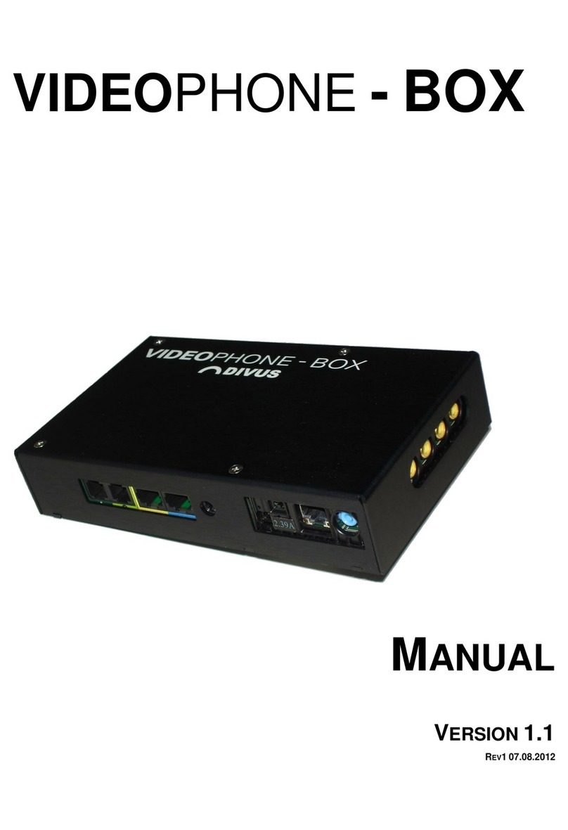
Divus OPENDOOR User manual

MANUAL
VERSION 2.1
REV107.08.2012

2
Headquarters
DIVUS –Pillhof 51 –I-39057 Eppan (BZ)
Tel. +39 0471 633662 –Fax +39 0471 631829
DIVUS Deutschland
DIVUS –Rainäckerstr. 39 –D-70794 Filderstadt
Tel. +49 711 70708490 –Fax +49 711 70708499
INDEX
1INTRODUCTION ___________________________________________________________________________________________________________________6
1.1 Presentation _____________________________________________________________________________________________________________6
1.2 Important terms _________________________________________________________________________________________________________7
2OD-SIP _____________________________________________________________________________________________________________________________9
2.1 Introduction _____________________________________________________________________________________________________________9
2.2 Connections______________________________________________________________________________________________________________9
2.3 Status LEDs_____________________________________________________________________________________________________________ 11
2.3.1 Power Supply ___________________________________________________________________________________________________________ 11
2.3.2 Status ___________________________________________________________________________________________________________________ 11
2.4 Configuration__________________________________________________________________________________________________________ 12
2.4.1 Introduction ____________________________________________________________________________________________________________ 12
2.4.2 Phone book_____________________________________________________________________________________________________________ 12
2.4.3 Settings VoIP ___________________________________________________________________________________________________________ 17
2.4.4 Settings Hardware ______________________________________________________________________________________________________ 22
2.4.5 Update__________________________________________________________________________________________________________________ 27
2.4.6 UDP status messages and remote control______________________________________________________________________________ 28
2.4.7 Create announcements and ring tones _________________________________________________________________________________ 29
2.4.8 Reset to factory settings ________________________________________________________________________________________________ 30
2.5 Techncal information _________________________________________________________________________________________________ 31
2.5.1 Dimension ______________________________________________________________________________________________________________ 31
2.5.2 Example for cover cutout _______________________________________________________________________________________________ 32
2.5.3 Compatible VoIP provider and VoIP server_____________________________________________________________________________ 32
2.5.4 Generic information ____________________________________________________________________________________________________ 33
3OD-CAM _________________________________________________________________________________________________________________________ 34
3.1 Introduction ___________________________________________________________________________________________________________ 34
3.2 Connections____________________________________________________________________________________________________________ 34
3.3 Configuration__________________________________________________________________________________________________________ 35
3.3.1 Introduction ____________________________________________________________________________________________________________ 35
3.3.2 Show Picture/Slideshow ________________________________________________________________________________________________ 36
3.3.3 View Video______________________________________________________________________________________________________________ 36
3.3.4 Remote Control_________________________________________________________________________________________________________ 37
3.3.5 User Settings____________________________________________________________________________________________________________ 37
3.3.6 System Settings_________________________________________________________________________________________________________ 38
3.4 Technical information_________________________________________________________________________________________________ 44
3.4.1 Dimension ______________________________________________________________________________________________________________ 44
3.4.2 Example for cover cutout _______________________________________________________________________________________________ 45
3.4.3 Generic information ____________________________________________________________________________________________________ 45

3
Headquarters
DIVUS –Pillhof 51 –I-39057 Eppan (BZ)
Tel. +39 0471 633662 –Fax +39 0471 631829
DIVUS Deutschland
DIVUS –Rainäckerstr. 39 –D-70794 Filderstadt
Tel. +49 711 70708490 –Fax +49 711 70708499
4OD-AUDIOCOMPACT ___________________________________________________________________________________________________________ 46
4.1 Introduction ___________________________________________________________________________________________________________ 46
4.2 Connections____________________________________________________________________________________________________________ 46
4.3 Display and controls __________________________________________________________________________________________________ 48
4.3.1 Display __________________________________________________________________________________________________________________ 48
4.3.2 Controls_________________________________________________________________________________________________________________ 48
4.3.3 Direct call keys__________________________________________________________________________________________________________ 48
4.4 Configuration__________________________________________________________________________________________________________ 49
4.4.1 Introduction ____________________________________________________________________________________________________________ 49
4.4.2 Phone book_____________________________________________________________________________________________________________ 49
4.4.3 Settings VoIP ___________________________________________________________________________________________________________ 50
4.4.4 Settings Hardware ______________________________________________________________________________________________________ 50
4.4.5 Update__________________________________________________________________________________________________________________ 50
4.5 Technical information_________________________________________________________________________________________________ 50
4.5.1 Dimension ______________________________________________________________________________________________________________ 50
4.5.2 Generic information ____________________________________________________________________________________________________ 51
5OD-VIDEOCOMPACT____________________________________________________________________________________________________________ 52
5.1 Introduction ___________________________________________________________________________________________________________ 52
5.2 Technical information_________________________________________________________________________________________________ 53
5.2.1 Dimension ______________________________________________________________________________________________________________ 53
5.2.2 Generic information ____________________________________________________________________________________________________ 53
6OD-SECURE ______________________________________________________________________________________________________________________ 55
6.1 Introduction ___________________________________________________________________________________________________________ 55
6.2 Connections____________________________________________________________________________________________________________ 56
6.3 Display, controls and accessories_____________________________________________________________________________________ 57
6.3.1 Status LEDs _____________________________________________________________________________________________________________ 57
6.3.2 Reset button ____________________________________________________________________________________________________________ 57
6.3.3 Sabotage switch ________________________________________________________________________________________________________ 57
6.4 Technical information_________________________________________________________________________________________________ 58
6.4.1 Generic information ____________________________________________________________________________________________________ 58
7OD-KEYPAD______________________________________________________________________________________________________________________ 59
7.1 Introduction ___________________________________________________________________________________________________________ 59
7.2 Function________________________________________________________________________________________________________________ 59
7.3 Technical information_________________________________________________________________________________________________ 61
7.3.1 Generic information ____________________________________________________________________________________________________ 61
7.3.2 Dimension ______________________________________________________________________________________________________________ 62
7.3.3 Example for cover cutout _______________________________________________________________________________________________ 63

4
Headquarters
DIVUS –Pillhof 51 –I-39057 Eppan (BZ)
Tel. +39 0471 633662 –Fax +39 0471 631829
DIVUS Deutschland
DIVUS –Rainäckerstr. 39 –D-70794 Filderstadt
Tel. +49 711 70708490 –Fax +49 711 70708499
8OD-TRANSPONDER _____________________________________________________________________________________________________________ 64
8.1 Introduction ___________________________________________________________________________________________________________ 64
8.2 Connections____________________________________________________________________________________________________________ 65
8.3 Programming __________________________________________________________________________________________________________ 65
8.4 Usage___________________________________________________________________________________________________________________ 66
8.5 Technical information_________________________________________________________________________________________________ 67
8.5.1 Generic information ____________________________________________________________________________________________________ 67
8.5.2 Dimension ______________________________________________________________________________________________________________ 68
9OD-PRESENCE ___________________________________________________________________________________________________________________ 69
9.1 Introduction ___________________________________________________________________________________________________________ 69
9.2 Connections____________________________________________________________________________________________________________ 69
9.3 Settings ________________________________________________________________________________________________________________ 70
9.4 Technical information_________________________________________________________________________________________________ 71
9.4.1 Generic information ____________________________________________________________________________________________________ 71
9.4.2 Dimension ______________________________________________________________________________________________________________ 72
10 DIVUS DESIGN _________________________________________________________________________________________________________ 73
10.1 Introduction ___________________________________________________________________________________________________________ 73
10.2 Assembly_______________________________________________________________________________________________________________ 73
10.2.1 OPENDOOR Frame _____________________________________________________________________________________________________ 74
10.2.2 OPENDOOR Cover______________________________________________________________________________________________________ 74
10.2.3 OPENDOOR Mount_____________________________________________________________________________________________________ 77
11 ACCESSOIRIES _________________________________________________________________________________________________________ 78
11.1 Introduction ___________________________________________________________________________________________________________ 78
11.2 OD-Push_LED __________________________________________________________________________________________________________ 78
11.2.1 Connections ____________________________________________________________________________________________________________ 78
11.2.2 Dimension ______________________________________________________________________________________________________________ 79
11.3 OD-BellModule ________________________________________________________________________________________________________ 79
11.3.1 Connections ____________________________________________________________________________________________________________ 79
11.3.2 Dimension and cutout __________________________________________________________________________________________________ 80
11.4 OD-Push________________________________________________________________________________________________________________ 80
11.4.1 Dimension ______________________________________________________________________________________________________________ 81
11.5 OD-Kit_Badge__________________________________________________________________________________________________________ 81
11.6 OD_S____________________________________________________________________________________________________________________ 81
11.7 OD_SBIT ________________________________________________________________________________________________________________ 82

5
Headquarters
DIVUS –Pillhof 51 –I-39057 Eppan (BZ)
Tel. +39 0471 633662 –Fax +39 0471 631829
DIVUS Deutschland
DIVUS –Rainäckerstr. 39 –D-70794 Filderstadt
Tel. +49 711 70708490 –Fax +49 711 70708499
12 APPENDIX______________________________________________________________________________________________________________ 83
12.1 Wiring schemes________________________________________________________________________________________________________ 84
12.1.1 Example with OD-Secure _______________________________________________________________________________________________ 84
12.1.2 Example without OD-Secure____________________________________________________________________________________________ 85
12.1.3 Example without OD-Secure with OD-Push_LED _______________________________________________________________________ 86
12.2 Recycling Information ________________________________________________________________________________________________ 87
12.3 Notes ___________________________________________________________________________________________________________________ 88

6
Headquarters
DIVUS –Pillhof 51 –I-39057 Eppan (BZ)
Tel. +39 0471 633662 –Fax +39 0471 631829
DIVUS Deutschland
DIVUS –Rainäckerstr. 39 –D-70794 Filderstadt
Tel. +49 711 70708490 –Fax +49 711 70708499
1INTRODUCTION
1.1 PRESENTATION
The OPENDOOR products were designed for VoIP technology, therefore they communicate over Ethernet. The product
range contains finished standalone solutions (AudioCompact, VideoCompact) as also compact modules, which can be
mounted into the own design (OD-Sip, OD-Cam..). Different accessories like for example an anti sabotage surveillance is
also available. Beside the use with Videophone, the OPENDOOR door stations can also be used in connection with SIP
capable telephone installations, VoIP servers of Internet providers with SIP support or the own VoIP server with SIP sup-
port; the SIP standard used by the OPENDOOR door stations makes this possible. In the further course of this manual, the
individual appliances and components will be explained:
OD-Sip
OD-Cam
OD-AUDIOCompact
OD-VIDEOCompact
OD-Secure
OD-Keypad
OD-Transponder
OD-Presence
DIVUS Design
Accessories
Hints for the usage of OPENDOOR with Videophone are marked with following sign:
General hints are marked with the following sign:
HINT: More information about the Videophone software can be found in the corresponding chapter.

7
Headquarters
DIVUS –Pillhof 51 –I-39057 Eppan (BZ)
Tel. +39 0471 633662 –Fax +39 0471 631829
DIVUS Deutschland
DIVUS –Rainäckerstr. 39 –D-70794 Filderstadt
Tel. +49 711 70708490 –Fax +49 711 70708499
Following scheme shows an example for the application of OPENDOOR with Videophone:
1.2 IMPORTANT TERMS
For better comprehension an explanation of some important terms will follow:
VoIP: "Voice over IP" is a international standard, which allows speech communication in a network. Developed
primarily for internet telephony, this technology is uesd also in other areas, as for example in telephone centrals
or the Videophone system.
VoIP server: This server is a software, which administers the telephone calls of the individual devices in the net-
work like a telephone central; the identification of the VoIP servers simply takes place over the IP address of the
device, on which the VoIP server is running. In a network also several VoIP server can coexist without problems;
it's only important that all devices, that should communicate among each other, uses the same VoIP server.
Client: A client is a software or a device, which can register on the VoIP server and make so calls to other clients;
The Videophone software is such a client. Each client is identified by a treble code (101,102,103…) and reachable
under this treble number.
In fact on one and the same PC the used VoIP server and the Videophone software as client can run without
problems; the Videophone software client will register locally at the VoIP server.
Videophone software: Software for the communication with the video intercom and for showing the picture of
the door camera, as well as for the communication of the individual clients among each other.
DTMF sounds: „"Dual-Tone-Multi-Frequency", is a standardized procedure for the transmission of the chosen
telephone number to the telephone network. Every sign corresponds to a certain sound, which consists of sev-
eral frequencies and is recognized from standardized telephone centrals and also from the telephone network.
OPENDOOR also uses this technology in order to execute an action through the transmitted DTMF sound to ac-
tivate for example the door opener. Only short sign combinations, but usually only single numbers are used for
DIVUSDOMUS
with Multime-
dia (Client)
Audio/Video
Network (LAN)
Audio/Video
Network (LAN)
Audio/Video
Network ( WI-FI )
OPENDOOR
Portable Ta-
blet-PC (Client)
DIVUS VS1
(VoIP server)
Audio/Video
Network (LAN)
DIVUS
TOUCHZONE
(Client)

8
Headquarters
DIVUS –Pillhof 51 –I-39057 Eppan (BZ)
Tel. +39 0471 633662 –Fax +39 0471 631829
DIVUS Deutschland
DIVUS –Rainäckerstr. 39 –D-70794 Filderstadt
Tel. +49 711 70708490 –Fax +49 711 70708499
this purpose. For example the OD-Sip module in his standard configuration will open the door if it receives the
digit “2” from the client as DMTF code during the opened speech communication.
Network stream: Essentially a network stream is a data flow, available over the network. In the case of OPEN-
DOOR (OD-Cam), the stream is build of single pictures, that are retrieved from the Videophone software as data
flow and showed in the main window of the Videophone software as video.
Backend: Main process of the Videophone software. It contains the entire functionality of the software and runs
in the background. Only through the "Popup" of the video window and the playback of the bell sound at a in-
coming call, the backend can be noticed.
GUI: "Graphical User interface". It's a graphic surface, over which the user can control the software. Also the Vid-
eophone software has an integrated "GUI."
Frontend: The frontend of the Videophone software is the integrated "GUI". over this graphic surface, the user
can configure the software and use the functions of the software.
UDP: "User Datagram Protocol". It is a simplified network protocol, over which the backend of the Videophone
software can be remote controlled. It can be used to create an individual "GUI" which can be used instead of the
Videophone software Frontend. Of course also the Videophone software frontend communicates with the
backend over UDP telegrams.

9
Headquarters
DIVUS –Pillhof 51 –I-39057 Eppan (BZ)
Tel. +39 0471 633662 –Fax +39 0471 631829
DIVUS Deutschland
DIVUS –Rainäckerstr. 39 –D-70794 Filderstadt
Tel. +49 711 70708490 –Fax +49 711 70708499
2OD-SIP
2.1 INTRODUCTION
The OPENDOOR Sip module is a very compact SIP phone device. The module was designed for mounting in personalized
housing like for example mailboxes, columns etc.; it can be installed also in the DIVUS design; too. The small dimension
and the extensive functionality make this device very flexible and applicable in a wide spectrum. The grommets around
loudspeaker and microphone prevent acoustic feedbacks directly on the device; the grommets must bear on the front
cover, where the OD-Sip is screwed on totally. With the built-in SIP standard, the device can be combined with a lot of
SIP systems (VoIP servers, IP phone calls, Internet telephony etc.). the configuration takes place in comfortable way over
the built-in web server through an intuitive menu. This makes it possible to maintain the device also from far away, if a
remote access from outside is possible.
2.2 CONNECTIONS
The OD-Sip module supports PoE (Power over Ethernet) and therefore can be power supplied and connected to the net-
work over the same network cable. The used network switch or router must support PoE for this purpose or a PoE-
injector must be used, which injects PoE into a normal Ethernet connection; the normal network connection is connected
on the input of the injector and on the output a network connection with PoE is available.
If a power supply over PoE should not be possible, the module can be power supplied also with 24V DC. For this purpose
the positiv pole of the power supply must be connected to "+UB" and the negative pole of the power supply must be
connected to "0V". A grounding of the module is possible over "PE."
.

10
Headquarters
DIVUS –Pillhof 51 –I-39057 Eppan (BZ)
Tel. +39 0471 633662 –Fax +39 0471 631829
DIVUS Deutschland
DIVUS –Rainäckerstr. 39 –D-70794 Filderstadt
Tel. +49 711 70708490 –Fax +49 711 70708499
Connections overview:
Left side
PE
Grounding
0V
Power supply
24V DC -
+VB
Power supply
24V DC +
Rel1.1
Relay 1
(dooropener)
Rel1.2
Rel2.1
Relay 2
Rel2.2
+24V
+24V EasyLan
ELAN
Bus EasyLan
GND
GND EasyLan
If more ring buttons are required, it's possible to connect up to 15 ring buttons through a binary conversion module on
"Z1"-"Z4". The binary transformer must generate the 4 bit binary value for each ring button on the connectors "Z1" -
"Z4". Bit0 must be connected to "Z1", bit1 to "Z2", bit2 to "Z3" and bit3 to "Z4".
HINT: The cables from the ring buttons to the OD-Sip should not be longer than 0.5m.
HINT: The OD-Sip backlight output can be used also for the OD-Push_LED. Normally there are always +5V on
the backlight output. Connection LEDB can be switched from GND to +24V what changes the backlight color
of OD-Push_LED from green to red.
HINT: If the OD-Sip is power supplied through PoE, it's should be checked, that the used switch/router/PoE-
injector does not have a standby or power down mode, where it reduces the PoE power or switch it off totally.
It's also important that the used switch/router/PoE-injector has enough power to power supply the OD-Sip.
Never connect the 24V DC power supply and PoE power supply at the same time to the OD-Sip!
HINT: If the OD-Sip is power supplied by a 24V DC power supply then on the network connection „Output“
there will be PoE power supply injected from the OD-Sip for power supplying a connected OD-Cam.
Right side
S3B
Switchboard
(Main Call)
GND
Switchboard
(Main Call)
GND
+5V
Ring button
/ nameplate
backlight
LEDB
Z1
Ring button 1/Matrix
Z2
Ring button 2/Matrix
Z3
Ring button 3/Matrix
Z4
Ring button 4/Matrix
GND
GND
OUTPUT:
Network connec-
tion with PoE for
OD-Cam
INPUT:
Network (LAN)
and PoE
Expansion port

11
Headquarters
DIVUS –Pillhof 51 –I-39057 Eppan (BZ)
Tel. +39 0471 633662 –Fax +39 0471 631829
DIVUS Deutschland
DIVUS –Rainäckerstr. 39 –D-70794 Filderstadt
Tel. +49 711 70708490 –Fax +49 711 70708499
2.3 STATUS LEDS
2.3.1 POWER SUPPLY
On the backside of the OD-Sip there are two LEDs: „PWR“ and „POE“, which indicates if the OD-Sip is power supplied
by PoE or by a 24V DC power supply:
PWR: this LED is on if the OD-Sip is power supplied; it doesn’t matter if the power comes from PoE or from a
external power supply; it just indicates, that the OD-Sip is power supplied.
POE: this LED is only on, if the OD-Sip is power supplied by PoE.
2.3.2 STATUS
On the bottom oft he OD-Sip there are 4 LEDs, which can be seen through a cutout in the housing:
IN: shows if a connection to the network is up (data input); if this LED is blinking data is read from the network.
OUT: shows if a connection with the network is up (data output); if this LED is blinking, data is send to the net-
work.
LED2 and LED1:
LED2
LED1
Description
off
off
If OD-Sip is power supplied it is in Idle mode and the connection with the VoIP
server is up (OD-Sip is registered on the VoIP server).
on
off
If OD-Sip is power supplied it is in Idle mode and the connection with the VoIP
server is not established (OD-Sip is not registered on the VoIP server).
off
on
A call is in progress or a speech communication is up from the OD-Sip to another
client. An incoming call is not signalled that way on the OD-Sip.
on
on
Changeover status: (special functions)
Factory settings are restored or starting save mode.
on
off
off
on
Crossover blinking: OD-Sip is in save mode.
off
blinking
Factory settings restored. Jumper can be removed.
blinking
off
Error on restore factory settings or more jumper mounted.

12
Headquarters
DIVUS –Pillhof 51 –I-39057 Eppan (BZ)
Tel. +39 0471 633662 –Fax +39 0471 631829
DIVUS Deutschland
DIVUS –Rainäckerstr. 39 –D-70794 Filderstadt
Tel. +49 711 70708490 –Fax +49 711 70708499
2.4 CONFIGURATION
2.4.1 INTRODUCTION
The configuration simply takes place over a web based menu. In order to start the configuration, simply open a browser
(for example internet Explorer or Firefox) and type in the IP address of the OD-Sip into the address bar; standard IP ad-
dress is "192.168.0.120":
4 submenus are available:
Phone book
Settings VoIP
Settings Hardware
Updates
For opening the whished submenu choose it, enter the passwort „1234“ and click on „Login; of course the passwort can
also be changed (standard is „1234“).
All this submenus will be explained in the following chapters, where all screenshoots shows the standard settings for the
usage with Videophone.
HINT: The submenus are only accesible if the OD-Sip has no ongoing call and no call is in progress. So
during a call no settings can be changed.
2.4.2 PHONE BOOK
The phone book contains all rules for incoming and outgoing calls on the OD-Sip and the call numbers for the single ring
buttons connected to the OD-Sip.
For each ring button in the phone book, there are always the same settings available:
Name: Like a comment through this field the ring button can be identified and also later it will be easy to re-
member the function of this ring button.
Number: In this field only numbers are allowed, alphanumerical characters can be entered, but they will not
work. These settings specifies the number to call, when the ring button is pressed. In this case the number

13
Headquarters
DIVUS –Pillhof 51 –I-39057 Eppan (BZ)
Tel. +39 0471 633662 –Fax +39 0471 631829
DIVUS Deutschland
DIVUS –Rainäckerstr. 39 –D-70794 Filderstadt
Tel. +49 711 70708490 –Fax +49 711 70708499
„20060101“ is entered, which is a group call on the VoIP server of Videophone, which calls all registered clients.
Otherwise it’s also possible to call only a single client, by entering for example „101“ in this field; only the client
„101“ will ring by pressing the ring button.
DTMF-Code: This code specifies with which DTMF code the door opener can be activated (normally Relay 1); up
to 4 digits are possible. For being able to recognize the DTMF-Code the OD-Sip must have an ongoing conver-
sation to another client (for example Videophone client).
Incoming: These settings define how to handle incoming calls. If a client calls the OD-Sip for the OD-Sip it will
be a incoming call. Following options are available:
oReject: the incoming call will be rejected immediately.
oAccept: the incoming call will be accepted immediately.
oAccept+Cheep: the incoming call will be accepted immediately with a short acoustic signal.
oAccept+Announcement: the incoming call is accepted immediately and the saved announcement is
played to the other client; so the first thing the calling client hears is the announcement.
oAccept+Annou.+Cheep: the incoming call is accepted immediately with a short acoustic signal and the
saved announcement is played to the calling client; so the first thing the calling client hears is the an-
nouncement.
oSignal calls: the OD-Sip doesn’t accept the incoming call immediately, but plays a acoustic signal to
signalize that there is an incoming call. The call will be accepted when a ring button is pressed; so the
OD-Sip acts like a phone.
Outgoing: Defines how the OD-Sip handles outgoing calls. The option are the following:
oAnnouncement Off: When the called client accepts the call, no announcement is played to it.
oAnnouncement On: When the called client accepts the call the saved announcement is played to the
client, so the first thing the called client hear after accepting the call will be announcement until it is
finished and only afterwards a speech conversion is possible.
Relay: If one of the two relays is configured for function “Light/Camera”, this parameter enables this relay to
close the contact, when the related “Number” is called by the OD-Sip, or when the client with this “Number” (SIP
ID) calls the OD-Sip. It means, that when the defined “Number” (SIP ID), calls the OD-Sip the relay will be
switched on until the call is accepted and during the whole communication, premised this parameter is set to
“On”; same thing happens when the OD-Sip calls a configured number in the phone book (SIP ID), premised this
parameter is set to “On”. The relay will switch off, when the call is dropped after the specified time delay.
Group-ID: Each „Number“ can be associated to a Group-ID; up to 10 Group-IDs are possible. This settings is on-
ly relevant for call chains. If a call chain is activated and a number of for example Group-ID “3” is called and the
client doesn’t accept the call, then the next number of the same Group-ID is called and so on.
HINT: „DTMF-Code“ should be set to „2“and the „Group-ID“ should be left to “None”. All other settings
can be set as whished. Numbers for group calls on the VoIP server of Videophone are 20060101,
20060201, 20060301, 20060401, 20060501, 20060601, 20060701, 20060801, 20060901 and 20061001; a
group call makes all clients ring in standard configuration of Videophone.

14
Headquarters
DIVUS –Pillhof 51 –I-39057 Eppan (BZ)
Tel. +39 0471 633662 –Fax +39 0471 631829
DIVUS Deutschland
DIVUS –Rainäckerstr. 39 –D-70794 Filderstadt
Tel. +49 711 70708490 –Fax +49 711 70708499
Switchboard
The Switchboard contains the settings for the ring button connected to the switchboard connectirs (Main Call); the first
two of the right terminal block on the back of the OD-Sip (see Chapter 2.2).
Call Keys (Z1-Z4 to GND)
This table contains the settings for the ring buttons connected to the screws „Z1“ to „Z4“ and GND. The four ring buttons
are valuated as 4-bit binary code. If one of the inputs is connected through the ring button to GND, the input get the
binary value “1”, otherwise it has the binary value “0”. Each row in the table contains the settings for the binary value on
„Z1 to „Z4“ concerning to the row number, where the first row has number “1” and the last raw has number “15”. This is
why raw „1“, „2“, „4“ and „8“ are used for the 4 inputs „Z1“ to „Z4“, because by pressing the ring button on „Z1“ you get
the binary value „1“, by pressing the ring button on „Z2“ you get the binary value „2“, by pressing the ring button on „Z3“
you get the binary value „4“ and by pressing the ring button on „Z4“ you get the binary value „8“.

15
Headquarters
DIVUS –Pillhof 51 –I-39057 Eppan (BZ)
Tel. +39 0471 633662 –Fax +39 0471 631829
DIVUS Deutschland
DIVUS –Rainäckerstr. 39 –D-70794 Filderstadt
Tel. +49 711 70708490 –Fax +49 711 70708499
Call Keys Matrix Modules
This table contains the settings for ring buttons connected to matrix modules, which can be connected to OD-Sip
through the expansion port. On each matrix module up to 15 ring buttons can be connected; max. up to 75 ring buttons
are possbile. For each matrix module there are 15 rows, one for each possible ring button on a matrix module. The tables
for the first four matrix module can be found in this submenu. If there is connected a fifth matrix module, the settings for
this one must be made in the submenu “Call keys (Z1-Z4 to GND).

16
Headquarters
DIVUS –Pillhof 51 –I-39057 Eppan (BZ)
Tel. +39 0471 633662 –Fax +39 0471 631829
DIVUS Deutschland
DIVUS –Rainäckerstr. 39 –D-70794 Filderstadt
Tel. +49 711 70708490 –Fax +49 711 70708499
Phone book
In the phone book additional SIP clients and their call numbers can be entered to be handled by OD-Sip in the whished
way. For example for each client could be specified another DTMF code, so each client must type another DMTF code to
open the door.
Unknown Caller
Often not all clients will be listed in the phone book, so there will be some clients who will be unknown to the OD-Sip.
This settings define how OD-Sip will handle calls to and from unknown callers. If the OD-Sip is used with Videophone,
then in the phone book group call numbers like „20060101“ are used. This numbers aren’t available in the system as cli-

17
Headquarters
DIVUS –Pillhof 51 –I-39057 Eppan (BZ)
Tel. +39 0471 633662 –Fax +39 0471 631829
DIVUS Deutschland
DIVUS –Rainäckerstr. 39 –D-70794 Filderstadt
Tel. +49 711 70708490 –Fax +49 711 70708499
ents and therefore the OD-Sip will get no incoming calls from such numbers, but all incoming calls from such clients will
be from unknown callers, promised, that there are no entries made in the phone book for their call numbers (SIP IDs).
2.4.3 SETTINGS VOIP
In this submenu all settings for VoIP and network can be found.
Network
This section contains following properties:
General Information: Information about hardware and firmware (Version, MAC address and product type)
Network settings:
oType of connection: determines whether the IP address is set manually or automatically by DHCP serv-
er.
oIP Address: the IP address can be specified here.
oSubnet mask: the subnet mask can be entered here.
oStandard gateway: the standard gateway can be entered here.
oGet DNS server IP automatically: determines if the IP address oft he DNS server is retrieved automati-
cally.
oUse following IP address: allows to determine manually an IP address of the a DNS server in the net-
work.
oPrimary DNS: the ip address of the primary DNS server can be entered here.
oSecondary DNS: the ip address of the secondary DNS server can be entered here.
oLayer 3 QoS: The „Quality of Service“ in the network should be changed only from network administra-
tors.
oLayer 2 QoS: The „Quality of Service“ in the network should be changed only from network administra-
tors.

18
Headquarters
DIVUS –Pillhof 51 –I-39057 Eppan (BZ)
Tel. +39 0471 633662 –Fax +39 0471 631829
DIVUS Deutschland
DIVUS –Rainäckerstr. 39 –D-70794 Filderstadt
Tel. +49 711 70708490 –Fax +49 711 70708499
Codec Settings
The VoIP technology uses speech codecs for communication. The codecs compress the speech in data packets, which can
be sent into the network. Which codecs whit which priority should be used by OD-Sip can be defined in this section. Fol-
lowing codecs are available:
PCMU (G.711 μ-Law) is a standard codec for digital communication in Europe. It has a good speech quality, but
also higher data volume about 80 to 100 kBit/s.
PCMA (G.711 A-law) ) is a standard codec for digital communication in America. It has a good speech quality,
but also higher data volume about 80 to 100 kBit/s.
Speex is optimized for transmitting speech and the data rate is very scalable. The standard setting 8 kBit/s
should be enough for a understandable conversion. Also the loss of data packets causes no problems.
iLBC (Internet Low Bitrate Codec) was designed especially for Speech transmission through IP networks. The da-
ta volume of this codec is about 14 kBit/s (20msec frame size) or 16 kBit/s (30msec frame size) and is really sta-
ble, also when data packages are lost.
G.726-32 has a data volume about 32 kBit/s with moderate speech quality.
GSM 6.10 comes from mobile telephony. This codec has really low data volume, but the speech quality is not
that good, is barely acceptable.
HINT: The setting for „iLBC Frame size“ and „Speex Rate“ should be changed only by system administra-
tors.
HINT: Only „PCMU“ as primary and „PCMA“ as secondary codec should be selected. In all other fields select
“None”.
HINT: For the usage with DIVUS TOUCHZONE the parameter “Audio Frames per Tx” must be set to “2”.

19
Headquarters
DIVUS –Pillhof 51 –I-39057 Eppan (BZ)
Tel. +39 0471 633662 –Fax +39 0471 631829
DIVUS Deutschland
DIVUS –Rainäckerstr. 39 –D-70794 Filderstadt
Tel. +49 711 70708490 –Fax +49 711 70708499
SIP Settings
Here can be found all basic settings for VoIP communication over the SIP protocol:
SIP registration: Defines if the OD-Sip should register on a VoIP server or not. If the registration is disabled only
IP to IP calls are possible, so only IP addresses can be called; a VoIP server isn’t needed any more in this function
mode. Without registration on a VOIP server no call numbers can be called any more, SIP clients can be called
only over through their IP addresses.
SIP Server: The IP address of the VoIP server or his url can be specified here.
SIP Server Port: Here the UDP port can be defined over which the SIP protocol will work.
SIP Domain: The domain is needed together with the target call number for pointing to the target sip client (for
example [email protected]). Without the domain no connection can be achieved. Instead of a domain name
also the IP address of the VoIP server can be entered.
SIP Server as Outbound Proxy: Defines if the VoIP server is used for outgoing calls; the VoIP server must sup-
port this feature. With this option enabled is possible to call outside through a NAT firewall.
Use DNS SRV: Defines if the defined DNS server from the network settings is used to reach the client oft he SIP
domain.
SIP User ID: This is the ID which identifies the OD-Sip inside the SIP domain. On a incoming call on the OD-Sip
the identification of the caller is made through this User ID which is transmitted inside the SIP protocol as
“<Number>@sipdomain.de” or better as “<ID>@sipdomain.de”. The ID and the call number of the calling de-
vice is the same number. In this way the OD-Sip is able to read from the phone book how to handle the incom-
ing call. In the same way the OD-Sip sends his user ID to a called client.
SIP authentication ID: User name for the registration on the VoIP server.
SIP authentication PIN: Password for the registration on the VoIP server.
Username: The name in this field is only for information and has no special function. For example here could be
entered the call number for the OD-Sip; it makes easier to manage the accounts of the clients.
HINT: All settings should be made like in the screenshot above with some variations:
„SIP Server“: IP address of the PC which is used as VoIP server; standard „192.168.0.101“.
„SIP Domain“: IP address of the PC which is used as VoIP server; normally same value as for „SIP
server“.
„SIP User ID“, „SIP authentication ID“, „SIP authentication PIN“ and „Username“ should all have the
same treble number defined, where one of the following numbers can be chosen: 901,902,903,
904, 905, 906, 907,908, 909 or 910; these numbers are already configured in the VoIP server.

20
Headquarters
DIVUS –Pillhof 51 –I-39057 Eppan (BZ)
Tel. +39 0471 633662 –Fax +39 0471 631829
DIVUS Deutschland
DIVUS –Rainäckerstr. 39 –D-70794 Filderstadt
Tel. +49 711 70708490 –Fax +49 711 70708499
Extenden SIP Settings
These settings should be changed only from system administrators with a good knowledge about VoIP communication,
because they can affect the SIP protocol; normally is not needed to make any changes here:
Local SIP Port: Through this port the SIP protocol manages the VoIP communication on the de-
vice.
Local RTP Port: The realtime transmission of the audio data is done through this port.
SIP Registration Timeout: This setting specifies the intervall for which the registration on the SIP
server is valid; everytime the interval is timed out the registration must be renewed by the device.
Keep Alive Interval: Specifies in which time interval an empty RTP packet is sent to the VoIP server
for keeping open the RTP port in a NAT firewall or a router.
Send DTMF: defines the method, with which the DMTF codes are sent to the client:
oInband Audio: DTMF tones are send inside the audio data as sound
oSIP Info: DTMF codes are transmitted inside the SIP protocol
oRFC 2833: DTMF codes are transmitted over RTP protocol
DTMF Payload Type: This setting should be left on his standard value. There are no special ad-
vantages for the user.
G.726-32 Payload Type: This setting should be left on his standard value. There are no special
advantages for the user.
iLBC Payload Type: This setting should be left on his standard value. There are no special ad-
vantages for the user.
Speex Payload Type: This setting should be left on his standard value. There are no special ad-
vantages for the user.
Support PRACK (RFC3262): If this option is activated specific signalizations are saved inside the
SIP protocol.
Required Proxy features: Properties, which the Proxy server must be able to handle.
NAT Traversal: If the OD-Sip is placed behind a NAT firewall or a router, this setting defines how
the OD-Sip gets his public IP address. This can be done through a fixed IP address by selecting
„Use NAT IP“ or by getting the public IP address from a STUN server by selecting „Use STUN serv-
Other manuals for OPENDOOR
1
Table of contents
Other Divus Intercom System manuals
Popular Intercom System manuals by other brands

Westinghouse
Westinghouse WHI-4CUPG - Voice Activated Intercom owner's manual

Vimar
Vimar PIXEL UP 40415.S user manual

Bticino
Bticino CLASSE 100X installation manual

Comelit
Comelit SIMPLEBUS 2 8472MB Technical manual

Chamberlain
Chamberlain EL1SS Installation and programming manual

ACO
ACO COMO-PRO-V Series Installation and user manual

Alpha Communications
Alpha Communications TekTone Tek-ENTRY installation instructions

VOS Systems
VOS Systems Video Intercom System Installation and operation manual

ring
ring Pro Power installation manual

Memco
Memco 492 021 installation guide

Comelit
Comelit 316 Touch Technical manual

Entrya
Entrya D22S Installation and user manual