5
• Always wear shoes.
• Ride on the correct side of the road, in a single le, and in a straight line.
• Bikes under 20” not intended for use on roads.
• Avoid riding at night, dusk, dawn and any other time of poor visibility.
• Make sure the reectors of your bicycle are correctly positioned. Do not remove
the reector or replace the reectors with lighted devices that look similar to
reectors.
• Do not let anything cover the reectors.
• Use extra caution in wet weather:
• Ride slowly on damp surfaces because the tires will slide more easily.
• Avoid these hazards to prevent loss of control or damage to your wheels:
• Be aware of drain grates, soft road edges, gravel or sand, pot holes or ruts, wet
leaves, or uneven paving.
• Cross railroad tracks at a right angle to prevent the loss of control.
• Avoid unsafe actions while riding.
• Do not carry any passengers.
• Do not carry any items or attach anything to your bicycle that could hinder your
vision, hearing, or control.
• Do not ride with both hands off the handlebar.
The Owner’s Responsibility
WARNING: This bicycle is made to be ridden by one rider at a time for general
transportation and recreational use. It is not made to withstand the abuse of stunting
and jumping.
If the bicycle was purchased unassembled, it is the owner’s responsibility to follow
all assembly and adjustment instructions exactly as written in this manual, and any
“Special Instructions” supplied and to make sure all fasteners and components are
securely tightened.
NOTE: Periodically check that all fasteners and components are securely tightened.
If the bicycle was purchased assembled, it is the owner’s responsibility, before riding
the bicycle for the rst time, to make sure the bicycle has been assembled and ad-
justed exactly as written in this manual, and any “Special Instructions” supplied and
to make sure all fasteners and components are securely tightened.
NOTE: If product is assembled, please proceed to the following sections:
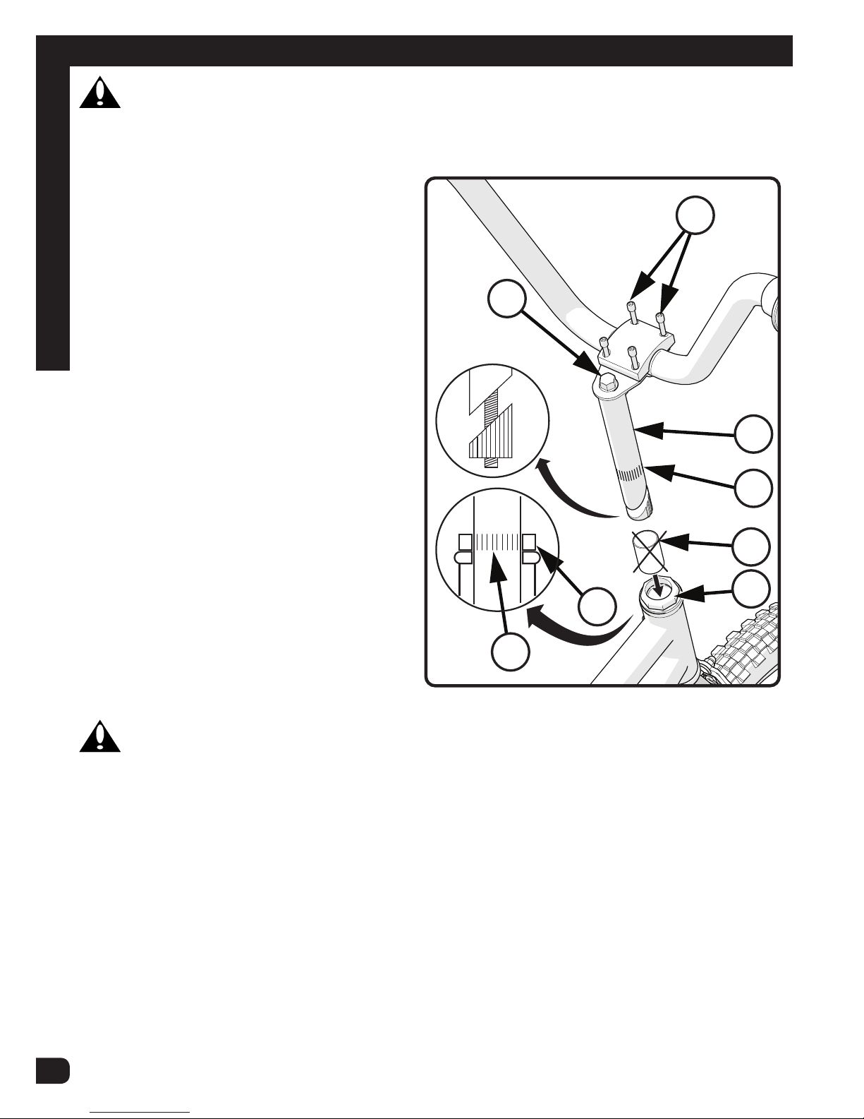
• Testing Seat Clamp and Post Clamp Tightness
• Testing Stem and Handlebar Tightness
Rules of the Road - continued
Introduction