DLI DIN4 User manual

DLI DIN4 User’s Guide
20170809T111540Z

CONTENTS 1
Contents
1 Overview 2
2 Product features 3
3 Package contents 4
4 Basic setup and use 5
5 LCD and keypad 10
6 Setup page 12
7 Scripting 19
8 Event notification 26
9 Customization page 33
10 External APIs 34
11 Backing up settings 40
12 Firmware upgrade 41
13 Date/time 43
14 AutoPing 44
15 System log 48
16 Locking down the controller 49
17 Resetting settings to defaults 51
18 Specifications 52
19 Open source code 53
20 Technical support 54
21 Limited one year warranty 55
DLI DIN4 User’s Guide: 20170809T111540Z

2 CONTENTS
1 Overview
Congratulations on selecting the DLI DIN relay, an industrial Ethernet controlled relay.
Check out the main product features. Some more technical specifications are available as well.
Be sure to check the package contents when unpacking the unit, then follow the instructions for basic setup and
use if you are a first-time user. The device is controllable using LCD and keypad, which have several modes. This
should allow you to access the basic device features. More advanced settings are located on the Setup page.
DLI DIN4 can be:
• extended with user scripts;
•customized to add branding;
• accessed via a growing number of external APIs;
•upgraded to newer firmware versions.
It can be configured to:
•ping other devices and take action if they don't respond;
• send notifications when certain events occur;
DLI DIN4 utility functions include:
• reading the system log
•setting date/time;
•backing up settings;
•locking down security-sensitive functionality;
•resetting settings to defaults.
The firmware is based on open-source code which is provided to give you the option to build totally custom firmware.
Please contact technical support in case of any problems.
We offer a limited one-year warranty on these units.
DLI DIN4 User’s Guide: 20170809T111540Z

2 Product features 3
2 Product features
Congratulations on selecting the DLI DIN Relay, an industrial Ethernet-controlled relay. Its features include:
• 8 SPDT Relay Outputs
Eight sets of single-pole double-throw contacts are provided. Screw terminals are rated at 6-10 amps over
commercial temperature range. T-90 relays are used with 15-30A 277V contact ratings.
• Universal Power Input
An internal bridge rectifier and switching power supply accepts from 9-24 volts AC or from 9-48 volts DC.
• Miscellaneous inputs
One 0-10VDC input, one 0-100VDC input, one temperature/relative humidity probe.
• Simple Web Interface
The internal web server is accessible from any browser. Simply enter an IP. Configuration and control are
web-based.
• AutoPing™ Reboot
AutoPing continuously monitors an IP address. If a server, router, or other peripheral goes down, AutoPing
can automatically reboot it without user intervention. Several devices can be monitored simultaneously.
• Programmable LCD Display
A 2x16 LCD displays status for each relay.
Custom messages can be displayed via user scripts.
• Multi-User Password Security
Multi-user authentication limits access to the power controller. The administrator selects which relays each
user can control.
• MOV Surge Suppression
Dual 3600W metal oxide varistors clamp power surges and spikes, protecting attached devices.
• Scripting Language, Syslog, and Utilities
Lua scripting can be used to create custom control and reboot sequences, schedule periodic reboots, etc.
Internal and external event logs are provided.
• New Features
New features include HTTPS, WiFi support and Lua scripting.
• Field Upgradeable Firmware
Firmware is field upgradeable via Ethernet or WiFi.
DLI DIN4 User’s Guide: 20170809T111540Z

4 CONTENTS
3 Package contents
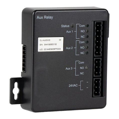
• DIN Relay 4.
• RP-SMA WiFi Antenna.
Please contact the freight carrier immediately if your package appears opened or damaged in transit. Call DLI at
(408) 330-5599 for tech support, service, and hardware upgrades.
DLI DIN4 User’s Guide: 20170809T111540Z

4 Basic setup and use 5
4 Basic setup and use
4.1 Factory defaults
The factory default network configuration is as follows:
• wired network: fixed IP address 192.168.0.100, netmask 255.255.255.0;
• wireless network: fixed IP address 192.168.254.1, netmask 255.255.255.0.
You can log in with username admin (lower case) and password 1234. It is recommended that you change the
password. You will be reminded to do so by a big red banner on the top of each page.
To reset to factory defaults, gently press the reset-to-defaults button below the LCD to enter the reset menu, then
select a reset option.
4.2 Initial setup
Use these shortcuts if you are an experienced installer. We recommend reading the entire manual for first-time
installation.
• Unpack. Save the carton.
• Apply power to the controller.
• Attach an Ethernet cable from the controller to your LAN. Switch power on. If you are attached through a
switch, you may need to cycle switch power to establish a connection.
• Ping the default address 192.168.0.100 to confirm that a network connection is established. If you don't
receive a response, proceed to the IP setup section below.
• Log in to the power controller using the default user name admin and the password 1234. Note: "admin" must
be entered in lower case.
• Click the Settings link to reach the configuration page. Select the safest power-loss configuration for your
installation: all OFF, all sequential ON or pre-powerloss state.
• Configure the power switch as described below. After each change, click Submit and wait for the page to
refresh before continuing.
Tip: An ohmmeter is handy for testing the relay. This ensures that it has been configured properly before attaching
your equipment.
4.3 IP setup
If your network settings won't access the default IP, use a direct cable connection (temporarily bypass any switch or
router) and follow these steps to add a compatible static IP, such as 192.168.0.50.
4.3.1 Windows IP setup
Before adding an IP, close all programs and browsers. After the link is established, you can enable DHCP.
DLI DIN4 User’s Guide: 20170809T111540Z

6 CONTENTS
4.3.1.1 Locating IP settings
In Windows, the first step is locating the network adapter TCP/IP properties. The procedure differs for each Windows
version:
Windows XP, 2000, 2003:
• Open Start / Control Panel / Network Connections.
• In "classic view", select Start / Settings / Control Panel /Network Connections.
• Right-click on Local Area Network Connection and select Properties.
• Proceed to step 2.
Windows Vista:
• Open Start, right click on Network, then on Properties.
• Double click Network and Sharing Center.
• Click Manage Network Connections. A Network Connections window appears.
• Right click on the network connection to the switch, i.e. Local Area Network.
• Proceed to step 2. Windows 7:
• Open the Start orb, click on Control Panel.
• Click View Network Status and Tasks, then Change Adapter Settings.
• Proceed to step 2
Windows 8:
• Mouse or swipe to the bottom right corner and select Settings.
• Select Control Panel.
• Select Network and Sharing Center.
• Change Adapter Settings.
• Right click on your connected network and select Properties.
• Proceed to step 2
4.3.1.2 Configuring static IP
The second step is adding an IP such as 192.168.0.50. Temporarily disable DHCP while configuring the switch.
• Select Internet Protocol TCP/IP V4 Properties and click Properties.
• Enter a compatible static IP such as 192.168.0.50.
• Click Apply and close windows.
• Ping the power switch to confirm the connection.
• Point your browser to 192.168.0.100
• Log in.
Detailed instructions are at http://digital-loggers.com/ip_setup.html
DLI DIN4 User’s Guide: 20170809T111540Z

4 Basic setup and use 7
4.3.2 Mac OS X IP setup
• Turn AirPort off temporarily.
• Click the Apple logo, then System Preferences, then Network.
• Select Built-In Ethernet and then Configure.
• Under the TCP/IP tab, select Manually
• Enter an IP address such as 192.168.0.1 as shown:
• Make changes shown.
• Point a browser to 192.168.0.100 Log in.
Find Mac setup details at http://digital-loggers.com/mac_ip_setup.html
4.4 Windows IP configuration (2000, 2003, XP, Vista)
If your default Windows settings won't access the controller, use a crossover cable and follow these steps to reach
the controller's IP:
1. Close network programs and browsers
2. Go to Network Settings ->Local Area Network.
3. Use the keyboard shortcut - type "ncpa.cpl" and click OK.
4. Right click on your LAN connection and choose "Properties".
5. Highlight "Internet Protocol" and click the "Properties" button.
6. Click the "Advanced" button.
7. Under the IP Address settings, click the "Add" button.
8. Enter a new IP, such as 192.168.0.10, and a subnet mask of 255.255.255.0.
9. Press the "Add" button; this new IP is added the list.
10. Close all windows for the configuration to take effect.
11. Start your Browser and type 192.168.0.100 in the URL field.
The default user name and password are "admin" (lower case) and "1234".
DLI DIN4 User’s Guide: 20170809T111540Z

8 CONTENTS
4.5 Basic switch operation
After power-up, the controller performs a sequence of self-tests to ensure reliability. The controller may then be
operated via a web browser. To access the controller, simply enter the IP address in the URL field of your web
browser, then log in. You will be presented with a screen similar to this:
Sessionexpiresin00:29:48
DIN4
RelayControl
Setup
Scripting
EventNotification
Customization
ExternalAPIs
Backup/Restore
FirmwareUpload
Date/Time
AutoPing
EnergyMonitor
SystemLog
Logout
Support
Help
Manual
FAQ
ProductInformation
DigitalLoggers,Inc.
Sourcecode
Version1.4.1.0/1.4.1.0
S/N:DIN42203123456
Controller:DLIController
WedFeb2405:18:392016
IndividualControl
# Name State Action
1 Relay1 OFF SwitchON
2 Relay2 OFF SwitchON
3 Relay3 OFF SwitchON
4 Relay4 OFF SwitchON
5 Relay5 OFF SwitchON
6 Relay6 OFF SwitchON
7 Relay7 OFF SwitchON
8 Relay8 OFF SwitchON
MasterControl
AllrelaysOFF
AllrelaysON
Cycleallrelays
Sequencedelay:3sec.
Main power controller page
Note that in this and many other pages, logical blocks can be collapsed by clicking in their right-hand corner,
and later expanded by clicking .
4.6 Common page layout
You can navigate the menu links to access the controller's features:
DLI DIN4 User’s Guide: 20170809T111540Z

4 Basic setup and use 9
Branding
Mainmenu
Customlinks
Power controller menu
Custom links can be configured on the Admin page. The branding block can be customized on the Customization
page.
4.7 Switching relays on and off
The relay control page lets you control relays. The sequence in which relays will be switched on is determined by
settings on the Admin page. To switch an relay on or off, simply click to the right of the relay name or number.
Switching an relay off is immediate. Switching an relay on may be delayed if a different (or possibly even the same)
relay was recently turned on. The delay acts to protect the device from simultaneous inrush currents and limit
cycling rate. You may also "cycle" a device which is connected to the controller. This feature is useful for rebooting
Ethernet devices which may interrupt the web link to the controller. Clicking "Cycle" switches power off, waits a few
seconds, and then switches power back on. This resets the attached device. You may also "cycle" all relays using
the "Cycle all relays" button on the bottom of the page. Depending on your web browser settings, you may need to
click the "refresh" button to update the on-screen status display after changing settings. A screen refresh setting is
provided on the Setup page.
4.8 Logout
Browser logout is automatic when a session is closed or after a time-out period. You can use a menu link to log-out
in advance.
DLI DIN4 User’s Guide: 20170809T111540Z

10 CONTENTS
5 LCD and keypad
The LCD has 2 lines, 16 character positions each. The displayed data depends on the mode, and possibly also on
user scripting.
The keypad has 5 keys:
• (UP),
• (DOWN),
• (ON),
• (CYCLE),
• (OFF).
During normal operation, the DIN4 LCD and keypad interface can be in one of the following modes:
• Relay mode, which displays status of and allows to manipulate the unit's relays;
• Network mode, which displays and allows to configure network settings.
You can cycle through the modes by pressing and keys simultaneously.
If the keypad is locked via web UI, the keypad doesn't work, and if you press a key, a message about this is displayed
and stays in place until the next update of the LCD data; no action is taken.
5.1 Network mode
Network mode
In Network mode, the and keys allow to select the network parameter.
Network configuration submode
Most values can be changed. Pressing the button allows to change the parameter. The leading character of the
first line, previously a whitespace , becomes an asterisk to indicate that.
Different kinds of values are changed in different ways:
DLI DIN4 User’s Guide: 20170809T111540Z

5 LCD and keypad 11
• for selectable options, like IP address mode, WiFi mode and encryption, the / keys cycle through the
available options;
• for netmasks, the / keys increase or decrease the mask;
• for IP and MAC addresses, a virtual cursor is used to allow modification of individual address bytes; the cursor
is initially placed on the last byte, and can be advanced to the preceding byte by presssing ; the /
keys increase or decrease the current byte's value;
• for the WiFi pre-shared key, any of the , or buttons generates a new key;
• the WiFi SSID can't be changed from keypad.
Pressing saves the current value and starts network reconfiguration if needed. The display isn't updated in-
stantly, and you need to refresh it by pressing / . You can cancel editing at any time by pressing
.
DLI DIN4 User’s Guide: 20170809T111540Z

12 CONTENTS
6 Setup page
The setup page allows the administrator to configure the power controller. These settings are supported:
6.1 Controller and relay names
UnitNames Confirm
Controllername
DLIController
Relay1name
Relay1
Relay2name
Relay2
Relay3name
Relay3
Relay4name
Relay4
Relay5name
Relay5
Relay6name
Relay6
Relay7name
Relay7
Relay8name
Relay8
Submit
Controller and relay names
Use the controller name fields to assign a Controller Name to the power controller itself. Examples are "Server
Rack Power Strip" or "Plutonium Refinery Control". The Controller Name field appears on the top of the home page.
Assign a separate name to each relay, such as "Missile Launcher" or "Email Server" to make identification of each
circuit simple.
6.2 Delays
Delay
Wrongpasswordlockout
60
minutes.(0-60)
ONsequencedelay
3
seconds.(1-255)
Cycledelay
0
seconds.(1-255)
Brown-outre-latchdelay
10
seconds.(1-255)
Refreshscreenevery
1
minutes.(1-255)
Enablescreenrefresh
Submit
Delays
DLI DIN4 User’s Guide: 20170809T111540Z

6 Setup page 13
When a time value is entered in the "All ON sequence delay" field, the power controller will pause for a period of time
before switching each relay on in sequence. This delay helps prevent the power surges and blown circuit breakers
which can occur when multiple devices are switched on simultaneously. A delay of 60 seconds is suggested for
server applications. You may also enter a screen refresh delay in this section. If "Enable screen refresh" is checked,
and a delay value is entered, your browser should periodically update the status screen.
6.3 Power loss recovery modes
PowerLossRecoveryMode
Whenrecoveringafter
powerloss
TurnallRelaysoff
TurnallRelayson
Returntopre-powerlossstate
Submit
Power loss recovery modes
The power loss recovery mode setting has three settings which take effect after a power failure:
1. You can turn all relays off (all systems will be switched off until manually turned on later) by checking the first
box.
2. You can automatically turn all relays on using the "All ON sequence delay" described above. Check the
second option to do this.
3. You can return to the same relay settings that were used prior to the power loss. The "All ON sequence delay"
will also be used in this instance. Click the third option to return to pre-powerless state.
6.4 User-defined links
# URL Description
User-defined links
You may link to other power controllers, your own web pages, or remote web sites by entering up to four URLs and
descriptions in the Setup page. For example, enter "Site Two Power Controller" in the description field with a URL
of "http://192.168.0.250/". These links appear on every page of the main web UI.
DLI DIN4 User’s Guide: 20170809T111540Z

14 CONTENTS
6.5 Network settings
General network settings
You can adjust the HTTP and HTTPS port bindings. If left empty, the corresponding service is not accessible. It
may be a good idea to disable HTTP if HTTPS satisfies your needs. Disabling both for security is possible; you can
use the LCD and keypad, or SSH to re-enable them if needed.
Enabling SSH will allow full control over the device, possibly bypassing most of the restrictions, e.g. setting protec-
tion. The SSH port is customizable as well. The SSH server also accepts public key authentication for a configurable
set of keys (the format is the same as in the authorized_keys file).
You can limit the severity of the locally recorded log messages by setting a minimal severity. Note that the local
log is circular, with old messages being replaced by newer ones; messages aren't persisted across reboots. For
persistent storage, you can configure the unit to send the system log to a syslog server. All messages, regardless
of severity, are sent; the receiver is expected to do the filtering.
Same subnet restriction can used to prevent remote access from outside. ONLY MACHINES IN THE SAME SUB -
NET WILL CONNECT AFTER ENABLING THIS. If connectivity is lost, use a local connection such as a laptop with
a crossover cable to restore your original network settings; you can also use the LCD and keypad for that.
DLI DIN4 User’s Guide: 20170809T111540Z

6 Setup page 15
6.5.1 Wired network settings
LANConfiguration
MACAddress
7C:E1:FF:00:00:00
Protocol
DynamicIP/DHCP
IPaddress
192.168.0.100
Subnetmask
255.255.255.0
Gateway
192.168.0.1
DNSservers,comma-
separated
192.168.0.1
Submit
Wired network settings
The device MAC address is provided for reference only and cannot be changed in this form. If you need to change
the MAC address, you may do so via LCD+keypad, SSH or using the REST-like API. Be sure you know what you're
doing, as e.g. assigning a conflicting MAC address, or a broadcast MAC address will make an interface unusable.
To configure the unit to use static IP assignment, a fixed IP address and network mask must be entered. If a
default gateway is specified it must be on the same subnet as the IP address specified. A number of DNS server IP
addresses can be supplied separated by commas, e.g. 192.168.0.1,8.8.8.8. If DNS servers are available,
some other configuration variables can accept hostnames instead of IP addresses.
If you wish to configure the unit to use DHCP IP assignment, you needn't change the IP, network mask, default gate-
way and DNS servers; rather, after the unit obtains a DHCP lease, the parameters will be displayed for reference.
It is recommended to configure the DHCP server to provide a static lease for the DIN4 using its MAC address (also
displayed).
When changing IP addresses, you may need to restart the unit and your network switch to validate the new IP on
an "auto-configuring" switch port.
DLI DIN4 User’s Guide: 20170809T111540Z

16 CONTENTS
6.5.2 Wireless network settings
Wireless network settings
The wireless network adapter has settings similar to those of the wired network adapter (see above), and adds
WiFi-specific ones.
It's possible to disable the wireless module entirely by unchecking the "WiFi module enabled" checkbox. The
wireless MAC address is configured to match the wired MAC address as the adapters will never be on the same
subnet in a regular setup. Use LCD+keypad, SSH access or the REST-like API if you need to change that.
The WiFi module can operate either in Access Point ("server") or Station ("client") mode. Either way, the name of
the wireless network to create/connect to must be specified as the SSID.
If the unit is configured to be an Access Point and have a static IP assignment, it starts a DHCP server on the
wireless interface.
It is possible to use no encryption on the WiFi channel, or one of the WPA, WPA2 or WPA/WPA2 mixed mode with
pre-shared key (the key has to be entered then). WEP encryption is considered insecure and is not supported.
Other encryption modes are not supported.
6.5.3 Network settings protection
You may press the "protect" button to lock the network settings (this will also affect the external API settings). Once
locked, the network settings cannot be changed except by pressing the physical reset button on the front of the unit.
DLI DIN4 User’s Guide: 20170809T111540Z

6 Setup page 17
6.6 Access control
The administrator's username and password can (and should) be changed from the default values. Note that you
need to provide the current password for confirmation.
Administrator credentials
In addition to the administrator, any number of users with individual passwords and relay permissions may be
configured on the setup page. Only the administrator can edit user names and passwords (users can only inspect
and switch relays).
User access control
Checkboxes to the right of each user name relay control access privileges. Users can only see and interact with the
chosen relays. For example, user 'harry' would see the following on login:
# Name State OFF/ON CYCLE
1 Relay4OFF SwitchON
3 Relay7OFF SwitchON
4 Relay8OFF SwitchON
Logout Help 3sec.
User relay control screen
Individual relays can be manipulated as usual. The top links allow switching all accessible relays on, off or cycling
them.
DLI DIN4 User’s Guide: 20170809T111540Z

18 CONTENTS
The next group is comprised of miscellaneous settings for access control.
Accesssettings
Allowlegacyplaintextlogin
methods
Hideuserpasswords
HideWiFipassword
Disablelocalkeypad
Showdevicenameonlogin
page
Submit
Access settings
If you need to access the controller with clients supporting Basic authentication, or by browsers without JavaScript,
you may need to enable the "Allow legacy plaintext login methods" setting. Those methods transmit passwords over
the network and are thus considered insecure. This includes Basic authentication over HTTPS, which is secure
relative to Basic authentication over HTTP, but relies solely on TLS for security, which is considered risky by some
experts. DLI Ethernet Sender should not require this setting.
The "Hide user passwords" and "Hide WiFi password" settings configure whether clients should be able to read
back the relevant values; this may be a security issue if there are untrusted administrator users.
The "Disable local keypad" setting is designed for untrusted physical environments. When enabled, the LCD will
briefly indicate that the keypad is disabled on each keypress and otherwise ignore it.
Note that this still leaves the reset button available to an attacker.
The "Show device name on login page" setting can be used to control if unauthenticated users can see the device
name (it used to be controllable by a space character preceding the device name in previous controller models, but
is now an individual setting). This may be a convenience, but also a possible security issue.
6.7 Miscellaneous settings
The following setting group controls aspects of data presentation of the unit.
MiscellaneousSettings
DisplayLCDtextinallCAPS
Meterandplotdefaultimage
format:
PNG
Submit
Miscellaneous settings
You can force all the text displayed on the LCD to be in CAPS, which may be more legible. However, this won't affect
the network settings, as they include the WiFi password which would be useless if capitalized.
DLI DIN4 User’s Guide: 20170809T111540Z

7 Scripting 19
7 Scripting
On its own, a power switch isn't very smart. Programmers can easily add custom functionality by using the built-in
Lua-based scripting language in power controllers.
7.1 Hardware requirements
Lua-based scripting is available in all DIN4 controllers. Beeper, backlight, LCD, voltage and current monitoring
functions are limited to products with appropriate hardware installed.
7.2 Entering scripts
First, for a quick overview of the script language visit the sample scripts page on the Digital Loggers web
site. Log in as admin and use the Scripting link to access the programming page.
Scripting is based on the Lua programming language. A brief introduction is done below, but you may want to
consult the general description, especially if you intend to write more complex scripts.
Script code is organized in functions. Configuration items which allow some scripting reaction to an event (reboot,
autoping failure, etc.) will ask you for the name of the function to call (you will be offered a list of the functions
defined in the script).
Scriptlisting
Save
--[[Thisisasample/testsetofscriptsforDLIpowercontrollers.
Thescriptingimplementationhaschanged,andisnolongercompatible
withtheolderBASICimplementation.Themostimportantchangesare:
-NowLua-based.
-Nomorelinenumbers,blocksofcodeidentifiedbyfunctions.
-MostofON,OFF,etc.arekeptaslegacyfunctions,whichcanbecalledlike
e.gON(2345),ON("2345")orON"2345",yourchoice.
Executionisstillbasedonthreads.Nowthreadsaremorevisibleand
manageable.Trystartingsomeandyou'llseethemappearinginthe
list.
]]--
functionturn_outlets_on()
ON(1)
ON(2)
ON(3)
ON(4)
ON(5)
ON(6)
ON(7)
1
2
3
4
5
6
7
8
9
10
11
12
13
14
15
16
17
18
19
20
21
22
23
User script source editor
You will need to define your functions to be able to use scripting. Simply putting calls to existing functions in the
script will not work. Functions are defined like this:
function my_function()
... statements go here ...
end
DLI DIN4 User’s Guide: 20170809T111540Z
This manual suits for next models
1
Table of contents

