DMX4ALL DMX-Relais/Analog Interface 4 User manual

DMX Relais/Analog Interface 4
User Manual

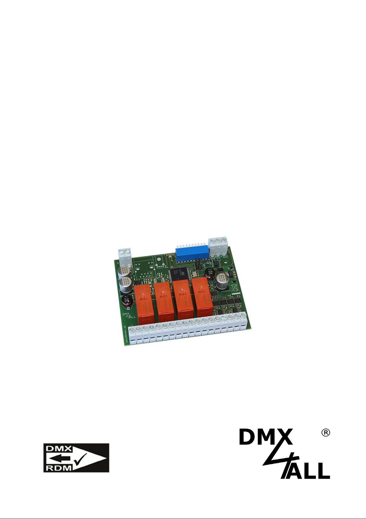
DMX Relais/Analog Interface 4 2
For your own safety, please read this user manual and warnings carefully
before installation.
Contents
Description.................................................................................................................. 3
Data sheet .................................................................................................................. 4
Max. DC load.............................................................................................................. 4
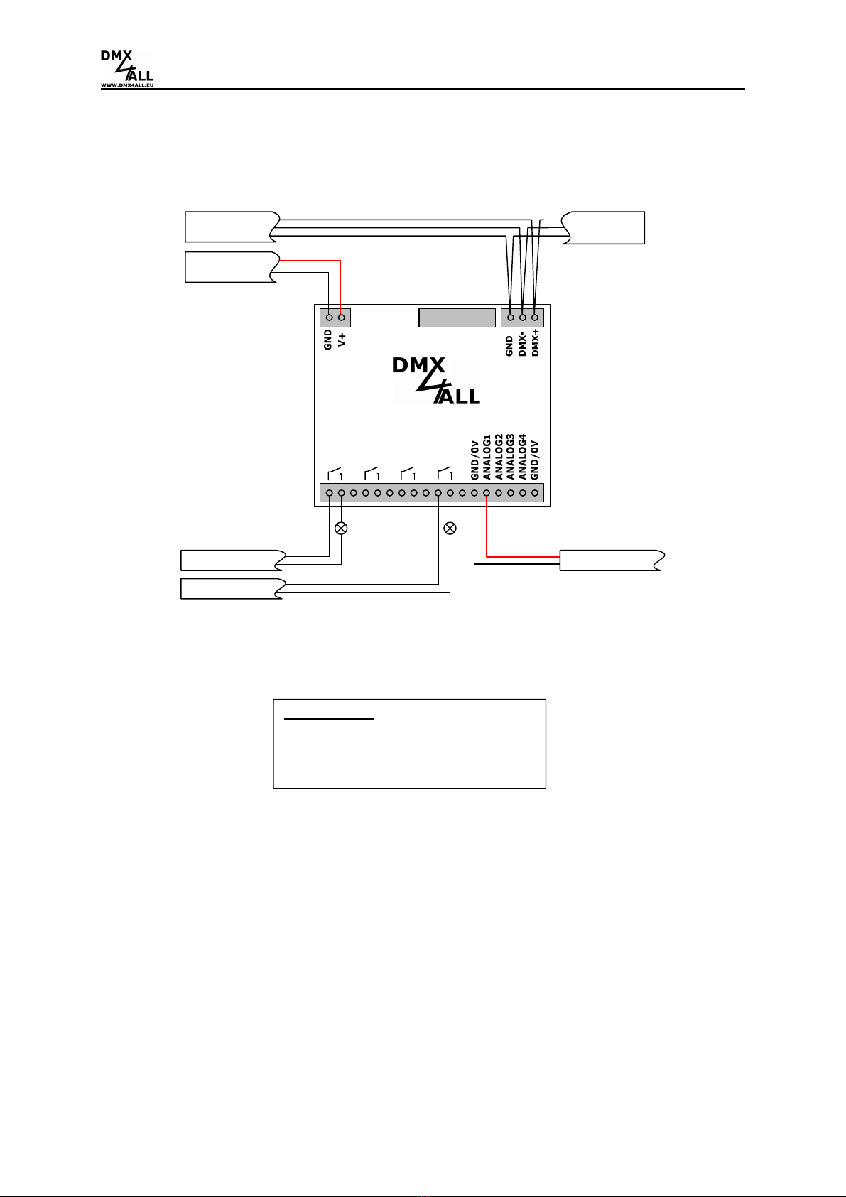
Connection ................................................................................................................. 5
LED-Display-Codes .................................................................................................... 6
Addressing.................................................................................................................. 6
Switch relay by an analog value greater than 0V........................................................ 7
Resolve the adjusted analog outputs.......................................................................... 8
Setting the output voltage 0-10V / 1-10V.................................................................... 9
DMX-FAIL Function .................................................................................................... 9
RDM ......................................................................................................................... 10
Dimensions............................................................................................................... 12
Equipment ................................................................................................................ 13
CE-Conformity .......................................................................................................... 14
Risk-Notes ................................................................................................................ 15

DMX Relais/Analog Interface 4 3
Description
The DMX-Relais/Analog Interface 4 is designed for several controlling tasks.
4 switch contacts for direct and alternating voltage
4 potential-free switching outputs (normally open / NO) with up to 8A switching
capacity for switching DC or AC voltage.
4 analog outputs
Four analog outputs with 0-10V vs 1-10V can be used to control systems with analog
inputs.
Analog outputs with 10mA
Each analog output has an output driver with max 10mA available.
For voltages from 12V up to 24V
The DMX-Relais/Analog Interface 4 runs with supply voltages from 12V up to 24V
DC.
DMX-FAIL Function
An adjustable DMX FAIL function offers the option to get in case of DMX signal loss
the current state (HOLD) or assuming a preset value.
LED-Status-Display
The LED status display shows DMX receipt.
RDM support
The DMX-Relais/Analog Interface 4 allows configuration by RDM via DMX.
Top hat rail housing available
The top-hat rail housing 1050 is available as accessory for the DMX-Relais/Analog
Interface 4.

DMX Relais/Analog Interface 4 4
Data sheet
Power supply: 12-24V DC
Power consumption: 200mA@12V; 140mA@24V
(without connected load at the analog output)
Protocol: DMX512
RDM
Input: 4 up to 12 DMX channels
Output: 4x switch contacts (Closer / NO)
165A@20ms peak switch-on current
AC: each max. 8A / 250V~
DC: According to the max. DC load graph
4x analog output 0-10V / 1-10V (max. 10mA)
DMX-FAIL: Hold / 0-100%
Connections: Screw terminals
Dimensions: 99mm x 82mm
Max. DC load
The maximum current the switch contacts of the DMX-Relais/Analog Interface 4
can switch is shown in the following graph depending on the switching voltage:
(Source: Data sheet RTS3T012)

DMX Relais/Analog Interface 4 5
Connection
DMX Relais/Analog Interface 4
ADDRESS
DMX OUT
12 3 4
POWER 12V
DMX IN
POWER
POWER
max. 10mA
ANALO OUT
Switch contact
AC: each max. 8A / 250V~
DC: According to the max. DC load graph
(165A@20ms peak switch-on current)

DMX Relais/Analog Interface 4 6
LED-Display-Codes
The integrated LED is a Multi-functional-display.
In the normal DMX-mode the LED flashes non-stop. In this case the device is
working. Is the LED permanently dark, there is no DMX512-signal at the entry.
Also the LED signalled the operation status. In this case the LED lights up in short
pitches and then turns into off modus. The Number of flashing signals is equal to the
number of the error status.
Error
Status
Error
Description
1 No DMX There is no DMX-signal at the entry
2 Address error Please check the adjusted starting address
Addressing
The DMX-starting address is adjustable via switch 1to 9.
Thereby switch 1 has the valency 2
0
(=1), switch 2 the valency 2
1
(=2) and so on until
switch 9 has the valency 2
8
(=256).
The sum of the values of the switches showing ON correspond to the starting
address.
Address
Switch Address
Switch
1
... ...
2
508
3
509
4
510
5
511

DMX Relais/Analog Interface 4 7
Switch relay by an analog value greater than 0V
This mode doesn’t use separate DMX-channels for the relays. The relay switches
immediately as soon as the analog value is greater than 0V or the DMX-value for the
analog output is greater than 0.
To activate this mode please set the MODE-Jumper 1:
In this case the DMX-channel assignment as follows:
DMX-channel configuration DMX-channel configuration
with 8 Bit: with10 Bit:
Relay and Analog separate adjustable
Relay switches by an analog value
higher than 0V
Start address Start address

DMX Relais/Analog Interface 4 8
Resolve the adjusted analog outputs
The analog output resolution will be adjusted via the MODE-Jumper 2.
The analog outputs are operable with a resolution of 8 Bit (256 steps) or 10 Bit (1024
steps).
Depending on the resolutions setting the analog output there is needed per output
one or two DMX-channels, as shown in the following picture.
DMX-channel configuration DMX-channel configuration
with 8 Bit: with 10 Bit:
8 Bit
(256 steps)
10 Bit (1024 steps)
Start address Start address

DMX Relais/Analog Interface 4 9
Setting the output voltage 0-10V / 1-10V
The analog outputs output voltage is adjustable via the MODE-Jumper 3:
v
DMX-FAIL Function
The DMX-Relais/Analog Interface 4 has a DMX-FAIL Function which stores the last
value in the case of a DMX-signal (HOLD) loss or uses a value set with RDM before.
The HOLD function can be activated via RDM or switch 10.
Switch 10 ON DMX-HOLD active
Switch 10 OFF DMX-HOLD not active
If HOLD is switched on (switch 10 = ON), the last received DMX values are kept in
case of a DMX signal failure.
If HOLD is switched off (switch 10 = OFF), the DMX values are replaced with a value
set by RDM in case of DMX signal failure. In delivery state this value is 0, so the
relays switch off.
In case of a power failure the held DMX values are rejected!
A value set by RDM is deleted when HOLD is selected.
After switching off the HOLD function the default value 0 is used!
0-10V
1-10V

DMX Relais/Analog Interface 4 10
RDM
(ab Hardware V1.2)
RDM is the short form for Remote Device Management.
As soon as the device is within the system, device-dependent settings can occur
remotely via RDM command due to the uniquely assigned UID. A direct access to the
device is not necessary.
If the DMX start address is set via RDM, all address switches at the DMX-
Relais / Analog Interface 4 must be set to OFF ! A DMX start address set by
the address switches is always prior !
This device supports the following RDM commands:
Parameter ID
Discovery
Command
SET
Command
GET
Command
ANSI/
PID
DISC_UNIQUE_BRANCH
E1.20
DISC_MUTE
E1.20
DISC_UN_MUTE
E1.20
DEVICE_INFO
E1.20
SUPPORTED_PARAMETERS
E1.20
PARAMETER_DESCRIPTION
E1.20
SOFTWARE_VERSION_LABEL
E1.20
DMX_START_ADDRESS
E1.20
DEVICE_LABEL
E1.20
MANUFACTURER_LABEL
E1.20
DEVICE_MODEL_DESCRIPTION
E1.20
IDENTIFY_DEVICE
E1.20
FACTORY_DEFAULTS
E1.20
DMX_PERSONALITY
E1.20
DMX_PERSONALITY_DESCRIPTION
E1.20
DISPLAY_LEVEL
E1.20
DMX_FAIL_MODE
E1.37

DMX Relais/Analog Interface 4 11
Parameter ID
Discovery
Command
SET
Command
GET
Command
ANSI/
PID
SERIAL_NUMBER
1)
PID:
0xD400
IDENTIFY_MODE
1)
PID:
0xD402
1) Manufacturer depending RDM control commands (MSC - Manufacturer Specific Type)
Manufacturer depending RDM control commands
:
SERIAL_NUMBER
PID: 0xD400
Outputs a text description (ASCII-Text) of the device serial number.
GET Send: PDL=0
Receive: PDL=21 (21 Byte ASCII-Text)
IDENTIFY_MODE
PID: 0xD402
Stellt den Mode ein der mit IDENTIFY_DEVICE ausgeführt wird.
GET Send: PDL=0
Receive: PDL=1 (1 Byte IDENTIFY_MODE_ID)
SET Send: PDL=1 (1 Byte IDENTIFY_MODE_ID)
Receive: PDL=0
IDENTIFY_MODE_ID
Funktion
0 FULL Identify
All relays switch ON / OFF simultaneously
and the status LED flashes
1 LOUD Identify
The relays switch ON / OFF one after the
other and the status LED flashes
2 QUIET Identify
The relays do not switch, only the status
LED flashes

DMX Relais/Analog Interface 4 12
Dimensions
(all details in mm)

DMX Relais/Analog Interface 4 13
Equipment
Top-hat rail housing 1050
Power supply 12V

DMX Relais/Analog Interface 4 14
CE-Conformity
This assembly (board) is controlled by a microprocessor and
uses high frequency. In order to maintain the properties of
the module with regard to CE conformity, installation into a
closed metal housing in accordance with the EMC directive
2014/30/EU is necessary.
Disposal
Electronical and electronic products must not be disposed
in domestic waste. Dispose the product at the end of its
service life in accordance with applicable legal
regulations. Information on this can be obtained from your
local waste disposal company.
Warning
This device is no toy. Keep out of the reach of children.
Parents are liable for consequential damages caused by
nonobservance for their children.

DMX Relais/Analog Interface 4 15
Risk-Notes
You purchased a technical product. Conformable to the best
available technology the following risks should not excluded:
Failure risk:
The device can drop out partially or completely at any time without warning. To
reduce the probability of a failure a redundant system structure is necessary.
Initiation risk:
For the installation of the board, the board must be connected and adjusted to
foreign components according to the device paperwork. This work can only be
done by qualified personnel, which read the full device paperwork and understand
it.
Operating risk:
The Change or the operation under special conditions of the installed
systems/components could as well as hidden defects cause to breakdown within
the running time.
Misusage risk:
Any nonstandard use could cause incalculable risks and is not allowed.
Warning: It is not allowed to use the device in an operation, where the safety of
persons depend on this device.

DMX4ALL GmbH
Reiterweg 2A
D-44869 Bochum
Germany
Last changes: 30.06.2022
© Copyright DMX4ALL GmbH
All rights reserve. No part of this manual may be reproduced in any form (photocopy, pressure, microfilm or in another
procedure) without written permission or processed, multiplied or spread using electronic systems.
All information contained in this manual was arranged with largest care and after best knowledge. Nevertheless, errors are to be
excluded not completely. For this reason, I see myself compelled to point out that I can take over neither a warranty nor the
legal responsibility or any adhesion for consequences, which decrease/go back to incorrect data. This document does not
contain assured characteristics. The guidance and the characteristics can be changed at any time and without previous
announcement.
Table of contents
Other DMX4ALL Recording Equipment manuals

DMX4ALL
DMX4ALL DMX Relais/Analog Interface 1 User manual

DMX4ALL
DMX4ALL DMX UNIVERSE DR1.1 RDM User manual

DMX4ALL
DMX4ALL ArtNet-DMX STAGE-PROFI 1.1 User manual

DMX4ALL
DMX4ALL Art-Net DMX STAGE-PROFI 1.1 RDM User manual

DMX4ALL
DMX4ALL NanoDMX USB Interface User manual

DMX4ALL
DMX4ALL DMX-Audio Unit User manual

DMX4ALL
DMX4ALL Art-Net DMX-UNIVERSE 4.1 User manual

DMX4ALL
DMX4ALL ArtNet-DMX-UNIVERSE 4.1 User manual

DMX4ALL
DMX4ALL Pixelkonig Wireless ArtNet-DMX STAGE-PROFI... User manual

DMX4ALL
DMX4ALL ArtNet Relais/Analog Interface 4 User manual