ii
TABLE OF CONTENTS
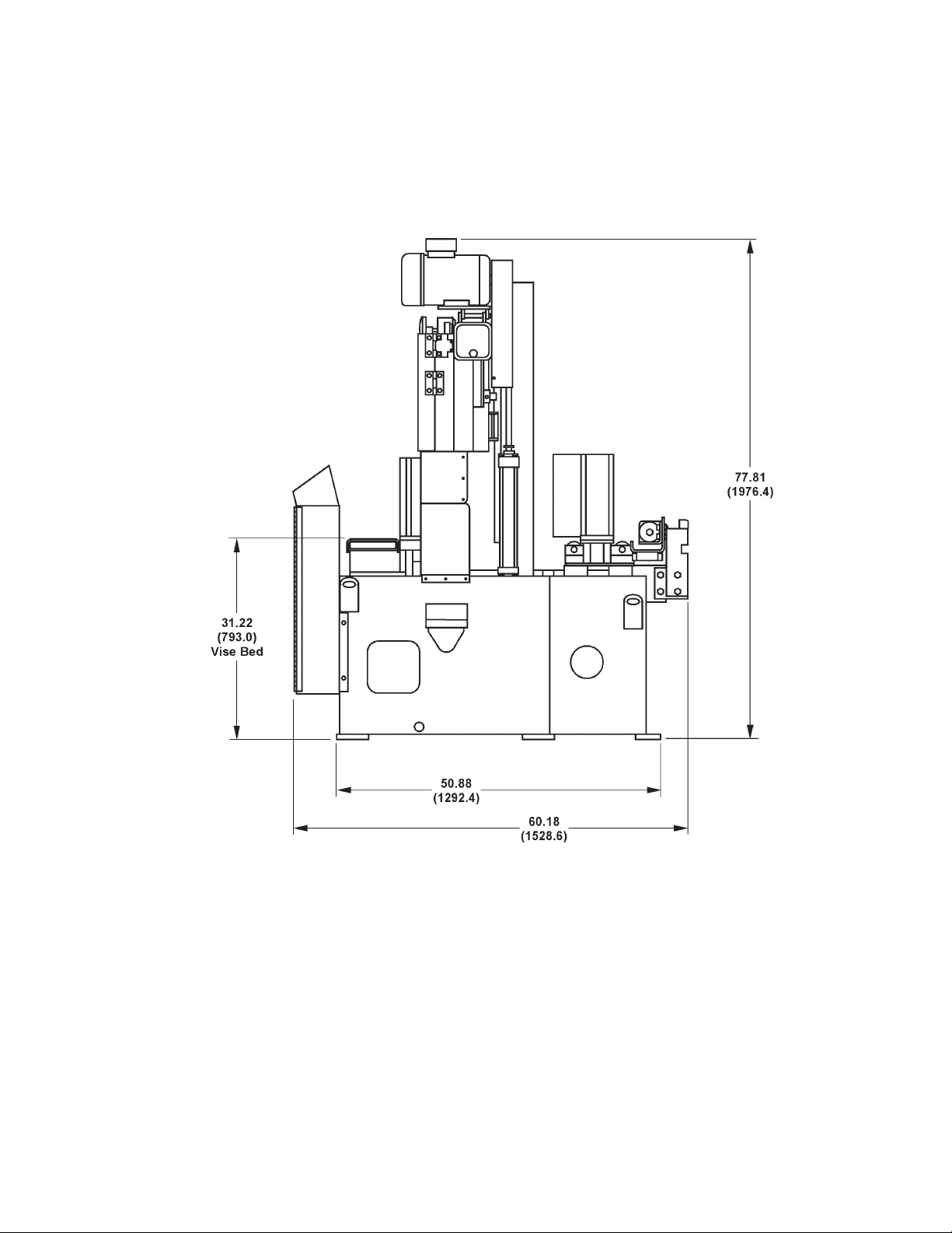
MACHINE DIMENSIONS
Floor Plan ............................................................... 1
Front View ............................................................. 2
Side View ................................................................ 3
MACHINE FEATURES
Front View .............................................................. 4
Rear View ............................................................... 5
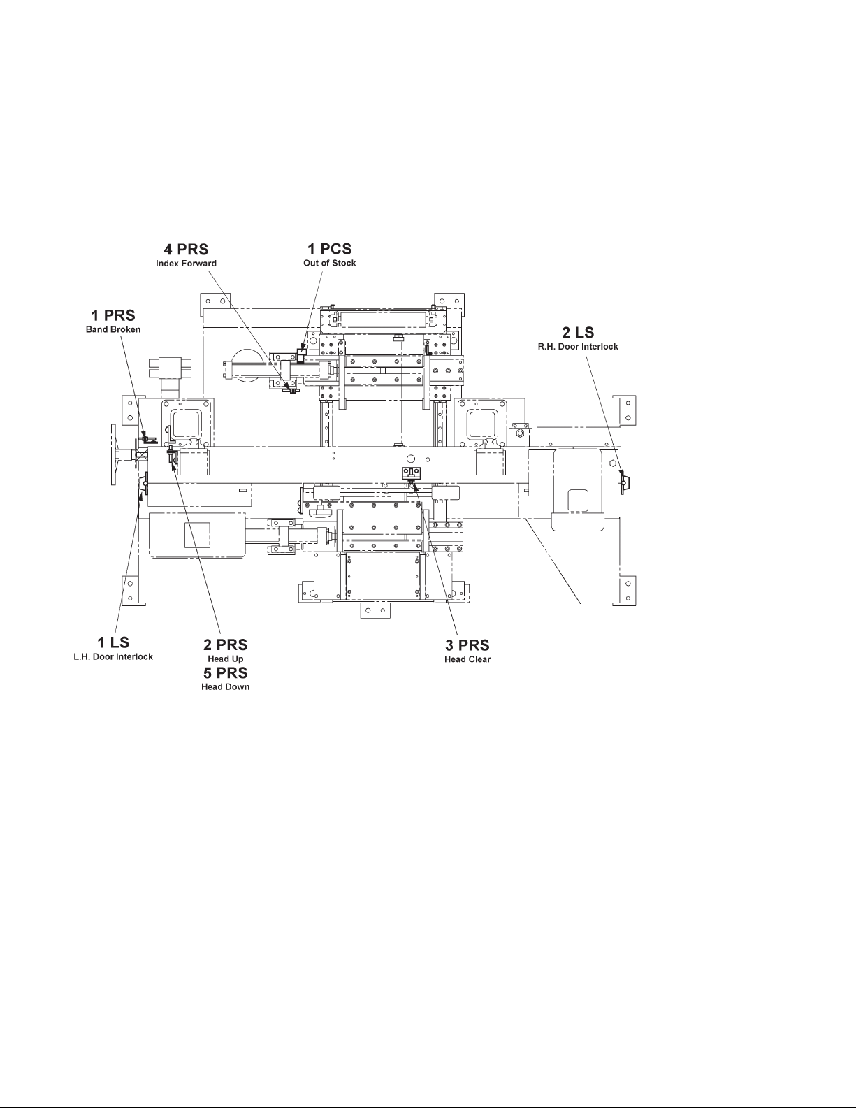
Proximity/Limit Switch Locations - Top View .......... 6
INSTALLATION
Location .................................................................. 7
OSHA Notice!! ........................................................ 7
Unpacking ............................................................... 7
Lifting ...................................................................... 7
Floor Installation ..................................................... 7-8
Electrical Installation ............................................... 8
Preparation for Use ................................................ 8-9
OPERATION
Safety Precautions ................................................. 10
Using the Job Selector ........................................... 10
Machine Capacities ................................................ 10
Machine Controls .................................................... 11-16
Saw Band Preparation ............................................ 16-18
Saw Guide Arm Adjustment .................................... 18
Feed Rate Adjustment ............................................ 18
Head Raise Limit Sensing Arm ............................... 19
Vise Jaw Adjustment .............................................. 19
Material Indexing .................................................... 19
Coolant Selection and Application .......................... 20
Dry Cutting .............................................................. 20
Band Brush and Chip Removal .............................. 20-21
Typical Operation Procedures ................................ 21-22
LUBRICATION
Lubrication Chart .................................................... 24
Lubrication Diagrams .............................................. 25
MAINTENANCE
Saw Guide and Back-Up Inserts ............................ 26
Band Drive Belt Replacement ................................ 26
Hydraulic System .................................................... 26-27
Coolant System ...................................................... 27
Machine Cleaning ................................................... 27
Machine Alignment ................................................. 27
Band Brush ............................................................. 27
Band Tension Measurement ................................... 28
Wear Plate Replacement ........................................ 28
Bandwheels ............................................................ 28
Cleaning Chip Trough/Chip Conveyor .................... 28
TROUBLE SHOOTING .................................. 29-32
ACCESSORIES
Roller Stock Conveyors .......................................... 33
Vertical Guide Rollers (Conveyors) ........................ 33
Variable Vise Pressure ........................................... 33
Nesting Fixture ....................................................... 34-35
Chip Conveyor ........................................................ 35
Mist Lubricator ........................................................ 35
Worklight ................................................................. 35
Material Handling .................................................... 35
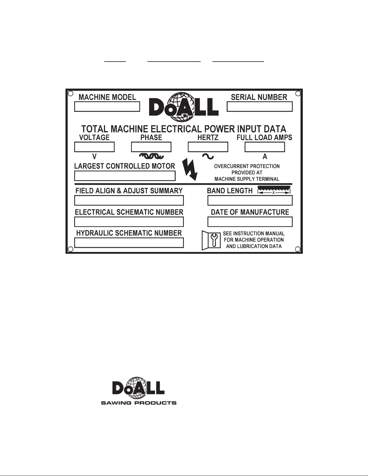
How to read your serial number: