laguna REVO 1216 User manual

Producent
Laguna Tools Inc
2072 Alton Pkwy
Irvine, CA 92606,
USA
Phone: +1 800-234-1976
Website: www.lagunatools.com
Distributor
IGM nástroje a stroje s.r.o.
Ke Kopanině 560, 252 67, Tuchoměřice
Czech Republic, EU
Tel: +420 220 950 910
www.igmtools.com
2021-12-17
151-1216 LAGUNA Woodturning Lathe Manual EN v1.8 A4ob
Woodturning Lathe
(Operating Instructions EN)
1216
www.igmtools.info
PDF ONLINE

-2-www.igmtools.com
EC DECLARATION OF CONFORMITY
We
(Manufacturer)
Laguna Tools Inc.
2072 Alton Parkway, Irvine, California 92606, USA
Declare that the product name: Wood Lathe
Model Name :
REVO 18│36 Lathe, REVO 24│36 Lathe, REVO 1216 Lathe, REVO 1524
Conform with the essential safety requirements of the relevant European Directive:
-Machinery Directive 2006/42/EC
-Electromagnetic Compatibility Directive 2014/30/EU
The person who compile technical file established within the EU:
Name:
IGM nastroje a stroje s.r.o.
Address:
Tel . :
Email:
Ke Kopanine 560, Tuchomerice , CZ-252 67
+420 220 950 910
sales@igmtools.com
Mounting and connecting instructions defined in catalogues and technical construction files must be respected
by the user.
They are based on the following standards:
EN ISO 12100:2010 Safety of Machinery - General principles for design / Risk Assessment and Risk reduction.
EN 60204-1:2006+AC:2010 Safety of machinery –Electrical equipment of machines, part 1 : General
requirements.
EN 13849-1:2015 Safety of machinery –Safety –related parts of control systems Part 1: General principles for
design
EN 50370 -1:2005 Electromagnetic compatibility (EMC) –Product family standard for machine tools –Part 1:
Emission.
EN 50370 -2:2003 Electromagnetic compatibility (EMC) –Product family standard for machine tools –Part 2:
Immunity.
EN 61000-4-2: 2009 Electrostatic (ESD)
EN 61000-4-4: 2012 Electrical fast transient/burst requirements (EFT/Burst)
EN 61000-4-6: 2014 Immunity to conducted disturbances, induced by radio-frequency fields (CS)
Responsible for the documentation: Head Product Management, Laguna Tools Inc.
Name : Torben Helshoj
Responsibility
Authorized Signature
Date : Oct. 15, 2021
Place : Laguna Tools Inc.
2072 Alton Parkway, Irvine, California 92606, USA
Telephone: +1 800 234-1976
Fax: +1 949 474-0150

-3-www.igmtools.com
Table of Contents
1. Declaration of Conformity
2. Warranty
3. Safety
Authorized Use
General Safety Notes
Hazards
Grounding Instructions
Woodturning Lathe
4. Machine Specication
External Description
Internal Description
Inventory
5. Transport and Setup
Receiving
Machine Placement
Unpacking
6. Setting and Adjustment
Installing Rubber Levelling Pads
Installing/Removing Faceplate & Hand Wheel
Installing/Removing Drive Centre and Live Centre
Removing Drive Centre
Removing Live Centre
Changing Speed Range
7. Machine Operation
First Use
Workpiece Clamping
Turning on the Lathe
8. Accessories
9. Maintenance
1. Declaration of Conformity
We declare that this product is in compliance with the directive and the
standard mentioned on the previous page of this manual.
2. Warranty
The company IGM Tools & Machinery s.r.o. always strives to deliver a
product of high quality and eciency.
The application of the warranty is governed by the valid Business
Conditions and the Warranty Conditions of the company IGM Tools &
Machinery s.r.o.
3. Safety
3.1 Authorized Use
Lathe is designed for sanding wood and wooden products only.
Sanding of other materials is not permitted.
The required minimum age must be observed.
The machine must only be used in a technically perfect condition.
In addition to the operating instructions, also read the safety requirements
and your country’s applicable regulations.
You should observe the generally recognized technical rules and safety
requirements concerning the operation of woodworking and metalworking
machines.
Neither the manufacturer nor the supplier is liable for damage resulting
from unauthorized use of the machine.
Responsibility is transferred exclusively to the operator.
3.2 General Safety Notes
Woodworking machines can be dangerous if not used properly.
Read and understand the entire operating manual before attempting
assembly or operation.
Protect this operating manual from dirt and humidity, and pass it over to
the new owner if you part with the machine.
No changes to the machine may be made.
Tighten all loose parts and locks before operating.
Daily inspect the function and existence of the safety appliances before
you start the machine. Correct all defects or damaged safety appliances
immediately. The machine must only be used in a technically perfect
condition.
Make all machine adjustments or maintenance with the machine
unplugged from the power source.
Protect long hair with a cap or hair net. Remove all loose clothing, rings,
watches and other jewellery. Wear safety shoes; never wear leisure shoes
or sandals. Do not wear gloves while operating this machine!
Follow personal protection guidelines.
Always wear safety goggles. Always wear ear protection. Tools are sharp
and can lead to serious injuries, handle them with care.
Install the machine so that there is sucient space for safe operation and
workpiece handling.
The machine must be bolted on rm and levelled surface and must be
properly lighted.
Only process workpieces without defects.
Keep pulley cover closed!
Always use tool rest when turning.
Always wear a protective mask in a dusty environment.
Keep work area well lighted.
Make sure the machine stands on a board.
Make sure that the power cord does not impede work. Keep work area
clean. Work only with well sharpened and clean tools.
Never reach into the machine while it is operating or running down.
EN - English
Operating instructions (Translation of original)
Dear Customer,
many thanks for the condence you have shown in us with the purchase of your new Laguna Tools machine. This manual has been
prepared for the owner and operators of an IGM LAGUNA Revo 1216 Woodturning Lathe to promote safety during installation,
operation and maintenance procedures. Please read and understand the information contained in these operating instructions and the
accompanying documents. To obtain maximum life and eciency from your machine, and to use the machine safely, read this manual
thoroughly and follow instructions carefully.
We wish you many work and personal pleasures when working with the Laguna Tools machine.

-4-www.igmtools.com
Stay alert! Give your work undivided attention. Use common sense. Do
not operate the machine under the inuence of drugs, alcohol or any
medication.
Keep children and visitors a safe distance from the work area. Never
leave a running machine unattended. Before you leave the workplace
switch o the machine.
Do not use the machine in a dump environment and do not expose it to
rain.
Focus on the position of your ngers and other parts of your body when
working. Do not start the machine without safety appliances.
Machine only stock which rests securely on the table.
Do not remove chips and workpiece parts until the machine is at a
standstill.
Clamp the workpiece only when the machine is switched o. Rotate the
workpiece by hand before starting the machine. Rough out the workpiece
before installing it on the faceplate.
Do not stand on the machine.
Use a suitable power cord that can handle the machine‘s power input.
Connection and repair work on the electrical installation may be carried
out by a qualied electrician only.
Have a damaged or worn power cord replaced immediately.
Make all machine adjustments or maintenance with the machine
unplugged from the power source.
3.3 Hazards
When using the machine according to regulations some remaining
hazards may still exist.
Thrown workpieces and workpiece parts can lead to injury.
Only process selected woods without defects.
Dust and noise can be health hazards.
Be sure to wear safety goggles, ear protection and dust mask.
Do not use damaged or worn power cord.
3.4 Grounding Instructions
Connection cord:
In case of a defect or malfunction, grounding provides a path of least
resistance to electric current, reducing the risk of electric shock. The
machine is supplied with connection cord with a guard wire and euro plug.
The plug must only be connected to an appropriate outlet in accordance
with all local codes and regulations.
• Do not modify the plug, if it does not t into the socket. Contact a
qualied electrician and have the appropriate socket installed.
• Improper connection may result in a risk of electric shock. Ground wire
is an insulated wire with a green surface with/without yellow stripes. If the
cord or plug needs to be repaired, contact a qualied electrician.
• Damaged cords should be repaired immediately and only by a
qualied electrician.
• Use only three-wire cables with a euro plug and an appropriate socket.
3.5 Woodturning Lathe
Woodturning lathes are typically used to shape wood into cylindrical
proles. Objects made on a wood lathe include items such as furniture
legs, lamp posts, baseball bats, bowls and other ornamental forms. Wood
lathe tooling consists of xturing and securing devices for the workpiece,
a moveable toolrest and hand-held cutting tools in the form of long
handled gouges, skews, scrapers and parting tools. Specialty tooling is
also available for internal shaping and surface development.
Electrical supply conditions - info for electricians
Voltage: Steady state voltage: 0,9 to 1,1 of nominal voltage.
Frequency: 0,99 to 1,01 of nominal frequency continuously; 0,98 to 1,02
short time.
Harmonics: Harmonic distortion not exceeding 10 % of the total r.m.s.
voltage between live conductors for the sum of the 2nd through to
the 5th harmonic. An additional 2 % of the total r.m.s voltage between
live conductors for the sum of the 6th through to the 30th harmonic is
permissible.
Voltage unbalance: Neither the voltage of the negative sequence
component nor the voltage of the zero sequence component in three-
phase supplies exceeding 2 % of the positive sequence component.
Voltage interruption: Supply interrupted or at zero voltage for not more
than 3ms at any random time in the supply cycle with more than 1s
between successive interruptions.
Voltage dips: Voltage dips not exceeding 20 % of the peak voltage of the
supply for more than one cycle with more than 1s between successive
dips.
Physical environment and operating conditions
Ambient air temperature: between 5° C to 40° C
Humidity: The relative humidity does not exceed 50 % at a maximum
temperature of 40° C.
Altitude: Up to 1000 m MSL.
Transportation and storage: Within a range of -25°C to 55° C and for short
periods not exceeding 24 hours up to 70° C.
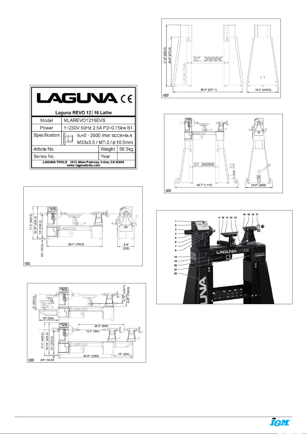
Locking the lathe
Fig. 1
Fig. 1: Method of locking Laguna Revo lathe. (1) Constructed 3 side
box with padlock holes. (2) Padlocks.
It is strongly recommended that the lathe is never left unattended in the
unlocked condition. To lock the machine it is recommended that a cover
(not supplied) is constructed.
4. Machine Specication
Motor specication
Power: 230V / 50 Hz / 1 phase
Power output: 0,75 kW, S1
(S1 - Permanent load)
Current at maximum load 2,5 A
Recommended circuit breaker 16 A, tripping
rating C (16/1/C)
Dimensions
Package dimensions (LxWxH): 920 mm x 380 mm x 520 mm
Package weight: 61 kg
Length x width x height: 750 mm x 226 mm x 442 mm
Weight: 56,3 kg
Floor to bed height (no pads): 170 mm
Floor to Spindle Centre height (no pads): 328,75 mm
Bed length: 746,8 mm
Toolrest length: 203,2 mm
Toolrest post diameter: 25,4 mm
Faceplate diameter: 76,2 mm
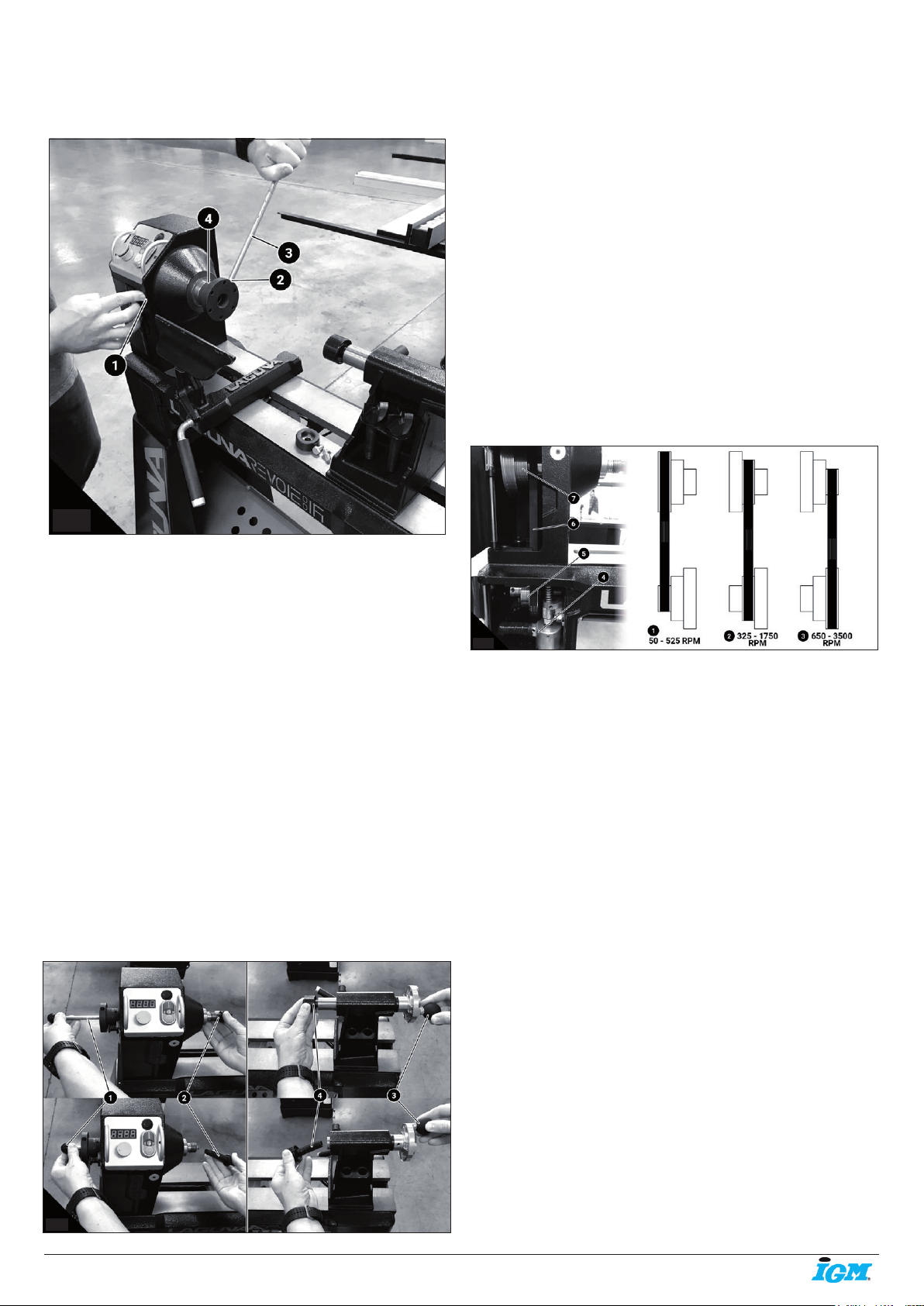
Lathe Specication
High Speed Range: 950 - 3500 RPM
Mid Speed Range: 450 - 1750 RPM
Low Speed Range: 100 - 525 RPM
Distance between Centres: 390 mm
Swing over Bed: 310 mm
Swing over Banjo: 241 mm
Spindle Bore: 9,5 mm
Spindle / Tailstock Taper: MK2 / MK2
Spindle Thread: M33 x 3,5 mm

-5-www.igmtools.com
Front Bearing: 6006LLU
Rear Bearing: 6005LLU
Indexing: 24 positions with lock
Inverter: PWM
Drive belt: 6 Groove Poly-V belt
Tailstock quill travel: 63 mm
Materials
Bed: Cast Iron
Head / Tailstock: Cast Iron
Legs / Base (optional): Steel
Toolrest: 1045 Steel
Toolrest Contact Rod: 6 mm Hardened 1045 Steel
Banjo: Cast Iron
Fig. 2
Laguna Revo 1216 Woodturning Lathe dimensions
Fig. 3
Revo 1216 Expansion Set 254 mm
Fig. 4
Revo 1216 Adjustable Stand
Fig. 5
Mobility Kit for 1412-14BX-1216
Fig. 6
4.1 External Description
Fig. 7
1 Headstock
2 Control Panel
3 Spindle Hand Brake
4 Indexing Lock
5 Indexing View Port
6 Spindle Lock
7 Upper Belt Door
8 Spindle
9 Banjo
10 Hardened Steel Leading Edge
11 Toolrest
12 Toolrest Lock
13 Banjo Lock
14 Quill Lock
15 Quill
16 Tailstock
17 Hand wheel
18 Expansion Mount
19 Lower Belt Door
20 Motor
21 Controller

-6-www.igmtools.com
damage on the bill of lading or refuse the shipment. Immediately call the
dealer store where the machine was purchased.
1. Never accept a shipment that is damaged or partial without notifying the
shipping company and the purchasing store.
5.2 Machine Placement
Prior to removing the machine from the packaging, decide the operating
location of the machine. He dimensions and oor space can be found
here: Dimensions.
1. There should be sucient area at the front of the machine to allow you
to work on it comfortably.
2. There should be sucient area at the back of the machine to allow
access for adjustments and maintenance to be conducted.
3. The better the lighting the more accurately and safely you will be able
to work.
4. You should select a solid at oor, preferably one made of concrete or
similar material.
5. Locate the machine close to a power source and dust collection.
5.3 Unpacking
Once in place, carefully unpack and remove all components. Unpacking
guidelines:
1. Do not cut deep into a box with a blade as it could scratch the paint.
Only cut deep enough to cut the tape or use a dull edge.
2. Organize the hardware and setup tools needed prior to proceeding with
setup.
6. Setting and Adjustment
Setting
WARNING! Never perform any setup, maintenance or adjustments with
the machine connected to the power source!
WARNING! If you have any doubt about the described procedure, seek
professional assistance. Do not attempt any procedure that you feel is
unsafe, or that you do not have the physical capability of achieving.
WARNING! When removing packaging banding, extreme caution must be
used as the banding will spring when cut.
CAUTION! The machine is heavy. Ensure that you have enough people to
do the job safely.
TIP There may be sawdust in or around your new machine as a result of
thorough testing.
TIP Numbers used to describe images are not the same as numbers used
to describe the individual parts in the Parts Section. This is done solely
to help with assembly and give better instructions to those receiving the
machine new. When ordering replacement parts, please only consult the
part numbers and reference images in the Parts Section.
The machine comes as assembled as possible without impacting
shipping costs. With this, there will always be some setup procedures and
adjustments that the craftsman must perform prior to using the machine.
These adjustments and setup procedures are intended to make the
machine work and operate safely.
Fig. 10
Fig. 10: Unpacking Revo 1216 Lathe. (1) Unpacking Contents. (2)
Lathe in a box. (3) Components unpacked.
6.1 Installing Rubber Levelling Pads
Rubber pads installed on the lathe reduce vibrations and protect the base
from the oor. Do not install rubber pads if you are planning to use the
stand.
Tools needed: 6mm Hex wrench
1. Make sure the lathe is unplugged and cannot be turned on.
2. Remove the tailstock and banjo (toolrest) from the lathe by releasing
the cam lock and sliding it o the end. NOTICE: You do not need to unbolt
anything to remove banjo or tailstock.
3. CAREFULLY tilt the lathe on its side. Use a blanket or similar soft thing
to cushion the side of the lathe in contact with the oor.
4. Install a washer, rubber pad, and screw on each corner.
22 Stand
4.2 Internal Description
Fig. 8
1 Front Bearing (Press Fit)
2 Spindle Lock Boring
3 Upper Belt Pulley Steps
4 Rear Bearing (Floating)
5 Indexing Lock
6 Spindle Hand Brake
7 Belt
8 Lower Belt Pulley Steps
9 Belt Tension Lock
4.3 Inventory
Fig. 9
1. Centre Knockout Rod PLAREVO1216-1103A. Used to release the
headstock centres.
2. Faceplate PLAREVO1216-104A. 76 mm (3“) faceplate used to fasten
workpiece.
3. Faceplate Wrench PLAREVO1836-1136. To release faceplate from
spindle threading.
4. Drive Centre PLAREVO1836-124A. Used in the headstock to turn a
workpiece. No bearing.
5. Live Centre PLAREVO1216-168. Used in the tailstock to keep the
workpiece rotating. Has a bearing.
6. 4x Rubber Foot PLAREVO1216-199. To limit vibrations - Remove if
using a stand.
7. 4x Screw for Rubber Foot PLAREVO1216-1100.
8. 4x Flat Washer PLAREVO1216-198.
5. Transport and Setup
5.1 Receiving
It is likely that your machine will be delivered by a third party. Before
unpacking, be sure to inspect the packaging and shipping documents
supplied by the driver. Ensure that there is no visible damage to the
shipment. If any damage has occurred because of shipment, note the

-7-www.igmtools.com
6.2 Installing/Removing Faceplate & Hand Wheel
WARNING! Unplug the machine from power source!
TIP Do not over torque the threading, only rm pressure is required.
TIP Remove set screws prior to removing faceplate. The screws are
located on the at part of the spindle. Do not disassemble by force.
Remove screws completely or you can damage the spindle.
Fig. 11
Fig. 11: Faceplate installation. (1) Spindle Lock. (2) Faceplate
wrenching hole. (3) Knockout rod or Faceplate wrench. (4) Set
screws.
Simply screw the faceplate intro the spindle threading. The spindle is with
M33 x 3,5 mm right hand threads. There is a cutting slot on the spindle for
the set screws.
Tools needed: Faceplate wrench (PLAREVO1836-1136) or Knockout rod
(PLAREVO1216-1103A) and 3mm Hex wrench
1. Make sure the lathe is unplugged and cannot be turned on.
2. Position the banjo out of the way to prevent damage.
3. Check that the set screws (Key 4) are not engaged. Remove all set
screws that are tightened down with Hex wrench.
4. Press the spindle lock (Key 1) inward to lock the spindle. Rotate the
spindle a bit to line it up with the pin hole.
5. With spindle lock (Key 1) engaged and set screws removed, t the
faceplate wrench (Key 3) into the faceplate wrenching hole (Key 2).
6. Turn counter clock-wise to remove the faceplate, turn clock-wise to
install the faceplate.
7. When installing, reverse these steps. TIP The faceplate wrench is not
needed for the assembly. If you over-tighten the set screws you could
damage the threading. Hand tightening is enough.
6.3 Installing/Removing Drive Centre and Live Centre
Warning! Unplug the machine from power source!
TIP Do not attempt to remove the live centre with tools, turn the quill until
it pops out.
TIP The centres pop out quickly, prevent from dropping.
Fig. 12
Fig. 12 - Centre Installation. (1) Knockout rod. (2) Drive Centre. (3)
Quill Hand Wheel. (4) Live Centre.
To install the centres, simply press them into the boring. When the
workpiece is loaded both centres will be pressed into a rm position.
Methods of centre installation vary.
6.4 Removing Drive Centre from Headstock
Tools needed: Knockout rod (PLAREVO1216-1103A).
1. Make sure the lathe is unplugged and cannot be turned on.
2. Lightly grasp the drive centre with free hand prior to step 3 - it will pop
out unexpectedly.
3. Use the knockout rod (Key 1) and lightly tap on the centre.
6.5 Removing Live Centre from Tailstock
Tools needed: none
1. Lightly grasp the live centre with free hand prior to step 2 - it will pop out
unexpectedly.
2. Turning the quill hand wheel (Key 3) counterclockwise will retract quill
and release the live centre from the quill.
6.6 Changing Speed Range
WARNING! Unplug the machine from power source!
CAUTION! Pinching hazard. Do no rotate the spindle with hands in the
belt cabinet.
TIP Do not attempt any other pulley congurations than those described
below.
Fig. 13
Fig. 13: Changing Speed Range. (1) Low Speed Range: 50-525 RPM.
(2) Mid Speed Range: 325-1750 RPM. (3) High Speed Range: 650-3500
RPM. (4) Belt Tension Cam Handle. (5) Drive Pulley. (6) Groove Poly-V
Belt. (7) Driven Pulley.
The lathe has three sets of pulleys for high, medium, and low speed
as described above. The belt should be tensioned so that there is
approximately 3 to 6 mm (1/8 to 1/4“) deection when the belt is pressed
with moderate thumb pressure. To adjust the amount of tension, see the
Adjustment section. To adjust between the speed ranges, follow these
steps:
Tools needed: none
Unplug the machine from power source!
2. Open both pulley covers to access upper (Key 7) and lower (Key 5)
pulleys.
3. To loosen the belt tension, turn the belt tension cam handle (Key 4)
towards you.
4. Move the drive belt (Key 6) to the required set of pulleys.
5. Tension the belt by returning the belt tension cam handle (Key 4) to its
original position.
6. Test that the belt is set correctly by manually turning the spindle prior to
returning power to the lathe.
7. Machine Operation
7.1 First Use
WARNING! Read the entire owners manual prior to using this machine.
WARNING! Never load or adjust the workpiece while the machine is
switched on.
CAUTION! The workpiece must be balanced to limit vibrations.

-8-www.igmtools.com
Fig. 14
Fig. 14: First use of 1216 lathe
7.2 Workpiece Clamping
1. Unplug the machine from power source. Install live centre into the
tailstock prior to clamping a workpiece.
2. Find the centre of the workpiece to be mounted with either the
faceplate or the drive centre. NOTE: A wood lathe chuck can also be used
to clamp a workpiece. The chuck must be compatible with the M33 x 3.5
spindle threading.
3. Fasten the workpiece to the faceplate or mount the drive centre onto
the centre of workpiece with a rubber mallet (NOTICE: do not use a metal
hammer) or clamp the workpiece in the jaws of the chuck (skip step 4).
4. Insert the faceplate or drive centre into the spindle. NOTICE: You may
need to remove the tailstock.
5. Replace the tailstock.
6. Fully release the quill by turning the hand wheel counter-clockwise.
7. Move the tailstock to the workpiece so that the live centre is circa 12
mm away from the workpiece.
8. Lock the tailstock in place with the cam lever.
9. Turn the hand wheel clockwise in order to seat the live centre intro the
centre of the workpiece. About 1/2 turn usually is enough, but it depends
on the hardness of the workpiece.
10. Tighten the quill locking handle.
11. Check that the workpiece rotates freely by using the spindle hand
brake prior to turning on the machine.
CAUTION! The workpiece must be balanced. Unbalanced workpiece
may vibrate too heavily and cause problems. Especially with live edge
pieces, remove any large abnormalities prior to clamping the workpiece. A
balanced workpiece will not assume any rotation orientation.
Personal protection and safety
Make sure to completely read and understand this manual. It is necessary
to follow these instructions to limit danger when using this machine.
7.3 Turning on the Lathe
1. Conrm that the belt is in the correct speed range. For speed range
adjustments see Changing Speed Range
2. Use appropriate personal protective equipment.
3. Conrm that all chisels and work tools are within close range and do
not require any reaching over the workpiece.
4. Plug in the machine to the appropriate socket.
5. Double check the workpiece balancing and rotation.
6. Turn on the lathe.
CAUTION! Do not start the lathe at maximum speed with a clamped
workpiece. Start at the lowest speed within chosen range. Then gradually
increase the speed.
8. Accessories
The following accessories are designed for the Revo 1216 Lathe. These
instructions should be followed exactly to properly set up the equipment.
Some of these accessories are designed to t multiple machines oered
by Laguna Tools.
IGM LAGUNA Revo 1216 Expansion Set 254 mm
Order code: 151-1216EXT
Compatibility: 151-1216
Fig. 15
Fig. 16
Fig. 16: (1) Bed extension - increased centre to centre from 393
mm to 647 mm. (2) Outboard turning - allows for 406 mm outboard
turning capacity
The lathe features forward and reverse spindle rotation as well as a
double threaded spindle that allows turning on both sides of the lathe. The
user can choose to extend the centre to centre capacity by 254 mm or
outt their lathe for outboard turning.
Contents:
The expansion set consist of 3 parts: 254 mm cast iron extension that can
be mounted on the right or left side of the lathe.
Toolrest extender for outboard use. Adapter that allows chucks with M33 x
3,5 mm to be used.
CAUTION! You have to use a reversible chuck with set screws attached
for outboard turning. Always tighten the set screws on the faceplate or
chuck to the spindle adapter / spindle for outboard turning.
Revo 1216 Expansion Set Setup
WARNING! Unplug the machine from power source!
TIP Do not over torque the threading, only rm pressure is required.
TIP The toolrest extension (2.2) and lock handle (2.4) are only used when
outboard turning.

-9-www.igmtools.com
Tools needed: Hex wrench
Receiving
It is likely that your machine will be delivered by a third party. Before
unpacking, be sure to inspect the packaging and shipping documents
supplied by the driver. If any damage has occurred because of shipment,
note the damage on the bill of lading or refuse the shipment. Immediately
call the dealer store where the machine was purchased.
1. Never accept a shipment that is damaged or partial without notifying
the shipping company and the purchasing store.
Stand unpacking
Fig. 17
Fig. 17: Unpacking Revo 1216 Expansion Set 254 mm. (1) Delivery
contents. (2) Components unpacked. (2.1) Extension Bed 254 mm.
(2.2) Toolrest Extension. (2.3) Extension Bed Bolts. (2.4) Lock
Handle. (2.5) Outboard Adapter.
Once in place, carefully unpack and remove all components. Unpacking
guidelines:
1. Do not cut deep into a box with a blade as it could scratch the paint.
Only cut deep enough to cut the tape or use a dull edge.
2. Organize the tools needed prior to proceeding with setup.
Components (Expansion Set 254 mm)
Fig. 18
Fig. 19
Fig. 17 - Fig. 19: Unpacking Revo 1216 Expansion Set 254 mm. (1)
Delivery contents. (2) Components unpacked. (2.1) Extension Bed
254 mm. (2.2) Toolrest Extension. (2.3) Extension Bed Bolts. (2.4)
Lock Handle. (2.5) Outboard Adapter.
Inventory
Key Name Description
2.1 Extension Bed Extends the bed length of the
lathe or can be installed to the left
side for outboard turning.
2.2 Toolrest Extension Only to be used when outboard
turning to raise the toolrest to the
appropriate position.
2.3 Hex Screws Attaches extension to the end of
the bed or to the lower outboard
turning position.
2.4 Lock Handle Locks the toolrest extension (2.2)
in place.
2.5 Adapter Adapter M33 x 3,5 mm
Setup Procedure
1. Make sure the lathe is unplugged and cannot be turned on.
2. Remove the tailstock and banjo (tool rest) by releasing the cam locks
and carefully sliding them out from the right side of the lathe.
Fig. 20
3. The bolt holes are pre-tapped. Lightly tighten all 3 screws (Key 2.3) and
slide the extension into the right side.
4. Reattach toolrest and tailstock. Position the tailstock so that half rests
on the bed and half rests on the extension (Fig. 20). Align the extension
and the bed, then tighten the screws.
2.5
Bed Extension

-10-www.igmtools.com
Fig. 21
5. Place the tailstock on the main bed for safe keeping.
6. The bolt holes are pre-tapped. Lightly tighten all 3 screws (Key 2.3) and
slide the extension into the left side.
7. Remove hand wheel or faceplate from left spindle threading.
8. Loosen outboard adapter set screws, lock spindle and screw in the
outboard adapter (Key 2.5).
9. Install the banjo on the extension by carefully sliding it into the left side
of the extension.
10. Install the toolrest extension (Key 2.2) into the neck of the banjo.
11. Install the lock handle (Key 2.4) into the toolrest extension (Key 2.2).
12. Install the toolrest into the toolrest extension (Key 2.2).
IGM LAGUNA Revo 1216 Adjustable Stand
Order code: 151-1216STA
Compatibility: 151-1216
Fig. 22
Fig. 23
Fig. 23: Revo 1216 Adjustable Stand. Includes adjustable lathe
stand and a tool rack. (1) Lowest position 990 mm (oor to spindle
centreline). (2) Highest position 1143 mm. (3) Tool Rack - holds
faceplate, both centres, knockout rod, 9 chisel tools with 25 mm
holes and 4 large tools with 34 mm holes. (4) Rubber Pads.
Revo 1216 Adjustable Stand Setup
WARNING! Unplug the machine from power source!
CAUTION! Two persons are required in this setup.
TIP Do not over torque the threading, only rm pressure is required.
Tools needed: Additional person, 6 mm Hex wrench, Phillips head
screwdriver and open ended wrench.
Receiving
It is likely that your machine will be delivered by a third party. Before
unpacking, be sure to inspect the packaging and shipping documents
supplied by the driver. If any damage has occurred because of shipment,
note the damage on the bill of lading or refuse the shipment. Immediately
call the dealer store where the machine was purchased.
1. Never accept a shipment that is damaged or partial without notifying the
shipping company and the purchasing store.
Stand unpacking
Fig. 24
Fig. 24: Unpacking Revo 1216 Adjustable Stand. (1) Contents. (2)
Stand in a box. (3) Contents unpacked.
Once in place, carefully unpack and remove all components. Unpacking
guidelines:
1. Do not cut deep into a box with a blade as it could scratch the paint.
Only cut deep enough to cut the tape or use a dull edge.
2. Organize the hardware and setup tools needed prior to proceeding with
setup.
Outboard Turning
Bed

-11-www.igmtools.com
Inventory
Fig. 25
Fig. 26
Fig. 26: Revo 1216 Adjustable Stand Inventory.
(1) Adjustable height pillars. (2) Stand Leg. (3) Tool Rack. (4) Rubber
pads, screws and washers. (5) Lathe attachment bolts and washers.
(6) Bolts and washers for assembly. (7) Height constraint screws.
Key Name Description
1
Height Pillar
PLAREVO1216-204
Main contact point from lathe to stand.
Allows for adjustable height.
2
Stand Leg
PLAREVO1216-201
PLAREVO1216-202
Sheet Steel constructed stand leg. Has
pre-tapped holes to mount. TECH TIP
These legs are not the same. You will
notice that the bolt holes that connect
the organization shelf are not at the
same height. The lower positioned bolts
holes must be front.
3
Organization Shelf
PLAREVO1216-203
Adds structural stability to stand. Also
holds 13 turning chisels/tools and all
functional set-up tools.
4 Rubber Pads
/Bolts/Washer
Used on the bottom of the stand legs to
minimize vibration.
5 Lathe Bolts/Washer Lathe to stand Fasteners.
6Assembly
Hardware
Height adjustment fasteners, shelf to leg
fasteners,
7 Height Constraint
Screw
Positions maximum height of
lathe stand.
Setup Procedure
1. Make sure the lathe is unplugged and cannot be turned on.
2. Remove the rubber pads from the lathe. This will give 6 rubber pads, 6
hex bolts and 6 washers.
3. Install the rubber pads (Key 4) to the stand legs (Key 2) with Hex
screws and washers.
Fig. 27
4. Identify the left and the right leg. There are four bolt holes on each leg
for the rack (Key 3). The upper two bolt holes must face the rear of the
machine, the lower two bolt holes must face the front of the workspace.
The rack is then installed so that is it angled towards the operator.
5. Identify the correct orientation of the tool rack (Key 3). The lip of the
rack should not be visible. In Fig. 17 the shelf is upside down. A properly
installed rack should have the largest hole (faceplate storage) on the
furthest left and towards the operator.
6. Fasten the stand legs to the tool rack. Use 8 bolts and washers (Key 6).
Tighten all screws at the end of the setup. TIP The stand will not be rigid
until it is fastened to the lathe. Once the lathe is attached and the height is
adjusted properly, it will be very rigid.
7. Install the height pillars (Key 1) to the stand legs with the remaining
eight bolts and washers (Key 6). Tighten all screws at the end of the
setup. TIP Assuming the nal height now is easier than later. Nevertheless
it can be positioned later.
8. Carefully reach into the stand leg and install the height constraint screw
on each pillar (Key 7). These screws will prevent the operator from pulling
the lathe out of the stand.
9. Using an additional person, place the lathe onto the stand. Attach the
lathe to the stand. CAUTION! One person must focus on holding the
position of the lathe while the other positions the four bolts and washers
(Key 5).
10. Tighten all bolts.
11. For safety, remove the lathe away from the stand if you would like to
change the height.
12. Avoid over tightening.
Three Rubber
Pads location. Hex Bolt
Washer
Pre-
Threadings
Rubber Pad (with
pre-installed
washer)

-12-www.igmtools.com
IMPORTANT: If the lathe is not level
1. Make sure the lathe is mounted to the stand.
2. Make sure oor is at.
3. Loosen all 16 bolts holding height position pillars and tool rack to
relieve all gaps.
4. Retighten all bolts.
IMPORTANT: If using the mobility kit, please remove the two rubber feet
closest to the two stationary wheels of the mobility kit.
Fig. 28
FAQ
Q: What is the height range with this stand?
A: The Revo 1216 Stand allows the spindle center line to be positioned at
7 dierent heights from 990 mm (39“) to 1143 mm (45“).
Q: Does this come with the mobility kit?
A: No, it comes standard with rubber pads.
IGM LAGUNA Mobility Kit for 1412-14BX-1216
Order code: 151-1412MBA
Compatibility: 151-1216STA, 151-1412, 151-14BX
Fig. 29
Fig. 30
Fig. 30: Mobility Kit for Revo 1216 Lathe. (1) Base Wheels &
mounting. (2) Foot Lever and Wheel Mount Assembly
Mobility Kit Setup
WARNING! Unplug the machine from power source!
TIPDo not over torque the threading, only rm pressure is required.
TIP Revo 1216 Adjustable Stand must be purchased to use the
Mobility Kit.
Receiving
It is likely that your machine will be delivered by a third party. Before
unpacking, be sure to inspect the packaging and shipping documents
supplied by the driver. Ensure that there is no visible damage to the
shipment. If any damage has occurred because of shipment, note the
damage on the bill of lading or refuse the shipment. Immediately call the
dealer store where the machine was purchased.
1. Never accept a shipment that is damaged or partial without notifying the
shipping company and the purchasing store.
Stand unpacking
Once in place, carefully unpack and remove all components.
Unpacking guidelines:
1. Do not cut deep into a box with a blade as it could scratch the paint.
Only cut deep enough to cut the tape or use a dull edge.
2. Organize the hardware and setup tools needed prior to proceeding with
setup.
Fig. 31
Fig. 32
Fig. 32: Unpacking (1) Contents. (2) Unpacked Contents. (2.1)
Stationary Wheels. (2.2) Foot Pedal Assembly. (2.3) Support Plate.
(2.4) Foot Pedal Caster. (2.5) Hardware. (2.6) Foot Pedal Spring. (3)
Swivel Axle.
Stationary Wheels
Same Spacing
REMOVE RUBBER PADS
FROM THE BASE

-13-www.igmtools.com
Inventory
Key Name Description
2.1 Stationary Wheels Can be mounted on left or right stand
leg. Must be positioned so that the
machine is o the oor when the foot
pedal is engaged.
2.2 Foot Pedal Assembly Must be positioned so that the
machine is o the oor when the foot
pedal is engaged.
2.3 Support Plate Mounts to the (inside) stand leg with
foot pedal assembly (2.2).
2.4 Foot Pedal Caster Mounts to foot pedal assembly (2.2).
2.5 Lathe Bolts and
Washers
Used to fasten the wheels to the
machine base.
2.6 Foot Pedal Spring Installs in between the caster (2.4)
and the assembly (2.2).
3 Swivel Axle Axle that spring (2.6) and caster (2.4)
are installed to.
Setup Procedure
Tools needed: Hex wrench, open ended wrench
Installing the Stationary Wheels
1. Make sure the lathe is unplugged and cannot be turned on.
2. Install the stationary wheels (Key 2.1) to either the left or the right stand
leg with 2 bolts and washers (Key 2.5). TIP Choose more suitable side for
mounting stationary wheels. It is often best to have the foot pedal caster
on the right side and the stationary wheels on the left side.
3. Remove the 2 rubber pads closest to the stationary wheels.
4. Make sure that the wheels are in contact with the oor and in the same
height.
Fig. 33
Installing the Foot Pedal Assembly and Wheel
The order of the assembly is: support plate, stand leg, foot pedal
assembly. The bolts thread into the support plate (Key 2.3). The support
plate is installed to the inside of the opposite stand leg that the stationary
wheels were installed to.
5. Place the foot pedal spring (Key 2.6) on the swivel axle (Key 3) of the
foot pedal assembly. Screw the foot pedal caster (Key 2.4) onto the swivel
axle.
6. Tighten the foot pedal caster with open ended wrench.
7. Release the foot pedal.
8. Place one bolt in the foot pedal assembly bolt slot.
9. Put together support plate, stand leg and foot pedal caster assembly.
Finger tighten the bolt.
10. Finger tighten the remaining bolts (Key 2.5). TIP We supply an extra
bolt.
11. When the foot pedal is not engaged, the foot pedal caster wheel
should be approximately at the same level as the rubber pads. Tighten all
bolts.
FAQ
Q: Does the wheel system aect the height of the lathe?
A: No, the two left wheels will always be in contact with the oor but only
at the same level as the caster. When the pedal is engaged the lathe
will prop up on the 3 wheels and is mobile. Releasing the pedal puts the
machine back on the oor.
IGM LAGUNA Industrial Flood Light for Revo1836-1412-14BX-18BX
Order code: 151-1836L
Compatibility: 151-1836, 151-18BX, 151-1216, 151-1412, 151-14BX
L-bracket for connecting the light to the rear of the headstock is not part of
the light supply, inquire about the options with your supplier:
Fig. 34
Fig. 35
9. Maintenance
WARNING! Unplug the machine from power source!
WARNING! If you have any doubt about the described procedure, seek
professional assistance. Do not attempt any procedure that you feel is
unsafe, or that you do not have the physical capability of achieving.
WARNING! When removing packaging banding, extreme caution must be
used as the banding will spring when cut.
CAUTION! The machine is heavy. Ensure that you have enough people to
do the job safely.
TIP There may be sawdust in or around your new machine as a result of
thorough testing.
General Notes
Keep your machine clean At the end of each work day, clean the machine.
Wood contains moisture. If sawdust or wood chips are not removed they
will cause rust. We recommend that you only use a Teon based lubricant.
Regular oil attracts dust and dirt. Teon lubricant tends to dry and has less
of a tendency to accumulate dirt and saw dust. Periodically check that all
nuts and bolts are tight.
Drive Belt
The drive belt should last for many years (depending on the usage) but
needs to be inspected regularly for cracks, cuts and general wear. If
damage is found, replace the belt.
Bearings
All bearings are sealed for life and do not require any maintenance. If a
bearing becomes faulty, replace it.
Rust
The lathe is made from steel and cast iron. All non-painted surfaces will
rust if not protected. We recommend to protect the lathe by applying wax
or a Teon based lubricant.
Changing the Belt and the Bearings
WARNING! Unplug the machine from power source!
TIP Do not over torque the threading, only rm pressure is required.
TIP Do not attempt to remove pulleys before removing set screws.
WARNING! Changing belt and bearings can be a dicult task and should
be performed by an authorized repair station.
Remove headstock and take it to a repair station for servicing.
Stationary Wheels
Same Spacing
REMOVE RUBBER PADS
FROM THE BASE

-14-www.igmtools.com
1. Unplug the machine from power source.
2. Open lower door and loosen the tension handle.
3. Remove the belt from the lower pulley
Fig. 36
4. Remove two set screws from the hand wheel.
5. Remove the hand wheel from the spindle by pushing in the spindle lock
and turning the hand wheel counter-clockwise.
6. Loosen 2 set screws in the upper pulley.
7. Use a wooden dowel or aluminium stock to knock spindle towards the
tailstock. Use a material that is softer than the spindle, so you do not
damage it. Remove the belt from the spindle.
8. Replace the belt or bearings.
9. Reverse these steps to reassemble.
TIP There is a wave washer between the right side of the upper pulley
and a black magnetic ring on the spindle. The black magnetic ring is
seated on the shoulder of the spindle. It is important for spindle speed
sensing. Make sure the upper pulley is pushing against the wave washer.
If not, the ring could slip on the spindle while you tighten the set screws
in the upper pulley. This will cause inaccurate spindle speed data on the
control panel.
TIP Tighten the hand wheel by hand
Lathe will not start.
1. Check that the start switch is in the correct position.
2. Check that the power cord is plugged into the socket.
3. Check that the electrical supply is on (reset the breaker).
4. With the power disconnected from the machine, check that the wiring to
the plug is correct.
5. Check that the rubber insulation is stripped enough and is not causing
a bad connection. Check that all the screws are tight.
The machine will not stop.
This is a very rare occurrence as the machine is designed to be fail-
safe. If it should occur and you cannot x the fault, seek professional
assistance. The machine must be disconnected from the power and never
run until the fault has been rectied.
1. The stop switch is faulty. Replace the stop switch.
Motor tries to start but will not turn.
1. With the power disconnected, try to turn the spindle by hand. If the
spindle will not turn, check the reason for jamming.
2. Capacitor faulty. Replace the capacitor.
3. Motor faulty. Replace the motor.
4. Power line overloaded. Correct overloaded condition.
5. Low voltage. Correct low voltage condition.
Squeaking noise.
1. Check the bearings.
2. Check the drive belt is tensioned correctly.
Spindle slows down during a cut.
1. Dull cutting tools. Replace the tool or have it resharpened.
2. Feeding the wood too fast. Slow down the feed rate.
3. Oil or dirt on the drive belt. Clean or replace the drive belt.
4. Drive belt loose. Re-tension drive belt.
Machine vibrates.
1. Machine not level on the oor. Re-level the machine ensuring that it
has no movement.
2. Damaged drive belt. Replace the belt.
3. Workpiece is not balanced. Change to slower speed and/or balance the
workpiece.
4. Damaged pulley. Replace the pulley.
5. Worn spindle bearing. Replace the bearing.
Digital Read Out (DRO) is displaying an error.
Err1:Over-current mode
If the operating current of the motor exceeds 10 Amps for 30s, the control
board goes into Over-current mode.
Over-current mode stops the motor immediately and the display shows Err1.
Do not use the lathe in reverse mode with the lowest revolution range on
the pulley (Slow: 50-100; Medium: 325-450; Fast: 650-950 RPM). At this
range, the over-current mode is triggered.
To release the Over-current mode:
• Press the STOP button.
• Press the START button. Control panel restarts the motor.
Err2: Motor work fail mode
After pressing the start button, if the motor is not running after 25s, the
control panel enters the Motor work fail mode
In the motor work fail mode, the control board immediately stops the motor
operation and the display shows Err2.
To release the Motor work fail mode:
• Press the STOP button.
• Press the START button. Control panel restarts the motor.
Err3:Spindle work fail mode
After pressing the START button, if the control board detects that the
spindle is not running for 30 seconds after the motor runs normally, it will
enter the Spindle work fail mode.
Spindle work fail mode immediately stops the motor and the display shows
Err3.
To release the Spindle work fail mode:
• Press the STOP button to release the Spindle work fail mode.
• Press the START button. Control panel restarts the motor.
Wiring
VOLTAGE. Before connecting this tool to a power supply make sure that
the voltage is the same as on the nameplate of the tool. IF IN DOUBT, DO
NOT PLUG IN THE MACHINE. Using this tool with a voltage dierent than
that stated on the nameplate can damage the electrical components of
this machine and any such damage will not be covered by a warranty.
CIRCUIT BREAKER Also make sure that the power supply is equipped
with the appropriate breaker and plug according to your local electrical
code. First check the motor plate to get the FLA amperage of the machine.
If it is worn out or not present, refer to the specications sheet. If there is
any doubt in choosing the appropriate circuit breaker, please consult an
electrician.
ELECTRICAL SHOCK It is extremely dangerous to work on live wires and
other electrical systems that are connected to a power source. Unplug the
machine from power source!
MOTOR WIRING: The information in this manual was current at the
time of printing but may be dierent than the diagram on your machine.
ALWAYS use the supplied wiring diagram with the machine or motor
(under the electrical covering) if present.
Parts
Unplug the machine from power source!
Only use authentic Laguna Tools parts for replacements.
Wave Washer
Rear Bearing
Hand Wheel Set Screws
Pulley Set Screws

-15-www.igm.cz
Parts
34
Parts
Never perform and setup, maintenance or adjustments with the machine connected to the power source!
Only use authentic Laguna Tools parts for replacements.
Revo 1216 Banjo, Tool Rest, Tail Stock, Centers
Key Part Number Description Specification Qty
16
PLAREVO1836-1119
Set Screw
1/4-20UNCx3/8"
5
52 PLAREVO1836-1113 Flat Washer D8xD18x2t 3
59 PLAREVO1216-159 8" Tool Rest 1
60 PLAREVO1216-160 E-RING E-10 2
61 PLAREVO1216-161 Tool Rest Support Base 1
62
PLAREVO1216-162
Clamp Bolt
1
63 PLAREVO1216-163 Clamp 2
64 PLAREVO1216-164 Lock Handle 1
65 PLAREVO1216-165 Tool Rest Locking Handle 1
66 PLAREVO1216-166 Rubber Sleeve 2
67
PLAREVO1216-167
Cap
2
68 PLAREVO1216-168 Live Center Assembly 1
69 PLAREVO1216-169 Quill 1
70
PLAREVO1216-170
Lead Screw
1
71 PLAREVO1216-171 E-RING E-12 2
72
PLAREVO1216-172
Tailstock Locking Handle
1
73 PLAREVO1216-173 Lock Handle 1
74 PLAREVO1216-174 Stop Bolt 1
75 PLAREVO1216-175 Handwheel 1
Key Part Number Description Specication Qty
16 PLAREVO1836-1119 Set Screw 1/4-20UNCx3/8" 5
52 PLAREVO1836-1113 Flat Washer D8xD18x2t 3
59 PLAREVO1216-159 8" Tool Rest 1
60 PLAREVO1216-160 E-RING E-10 2
61 PLAREVO1216-161 Tool Rest Support Base 1
62 PLAREVO1216-162 Clamp Bolt 1
63 PLAREVO1216-163 Clamp 2
64 PLAREVO1216-164 Lock Handle 1
65 PLAREVO1216-165 Tool Rest Locking Handle 1
66 PLAREVO1216-166 Rubber Sleeve 2
67 PLAREVO1216-167 Cap 2
68 PLAREVO1216-168 Live Center Assembly 1
69 PLAREVO1216-169 Quill 1
70 PLAREVO1216-170 Lead Screw 1
71 PLAREVO1216-171 E-RING E-12 2
72 PLAREVO1216-172 Tailstock Locking Handle 1
73 PLAREVO1216-173 Lock Handle 1
74 PLAREVO1216-174 Stop Bolt 1
75 PLAREVO1216-175 Handwheel 1
76 PLAREVO1216-176 Tailstock Tool Caddy 1
77 PLAREVO1216-177 Screw 5/16-18UNCx1/2" 2
78 PLAREVO1216-178 C-RING S10 1
79 PLAREVO1216-179 Clamp Bolt 1
81 PLAREVO1216-181 Tailstock 1
102 PLAREVO1216-1102 bushing 1
103 PLAREVO1216-1103 Knockout Rod 1
104 PLAREVO1216-1104 Knob 1
107 PLAREVO1836-181 Knob 1
111 PLAREVO1836-1136 Handle, Faceplate 1
114 PLAREVO1216-1114 Nylon Insert Lock Nut 3/8-16UNC 2
Revo 1216 Banjo, Tool Rest, Tail Stock, Centers

-16-www.igm.cz
Revo 1216 Headstock Assembly
Parts
35
Revo 1216 Headstock Assembly
76 PLAREVO1216-176 Tailstock Tool Caddy 1
77 PLAREVO1216-177 Screw 5/16-18UNCx1/2" 2
78
PLAREVO1216-178
C-RING
S10
1
79 PLAREVO1216-179 Clamp Bolt 1
81
PLAREVO1216-181
Tailstock
1
102 PLAREVO1216-1102 bushing 1
103 PLAREVO1216-1103 Knockout Rod 1
104 PLAREVO1216-1104 Knob 1
107 PLAREVO1836-181 Knob 1
111
PLAREVO1836-1136
Handle, Faceplate
1
114 PLAREVO1216-1114 Nylon Insert Lock Nut 3/8-16UNC 2
Key Part Number Description Specification Qty
1 PLAREVO1836-1140 Thimble 1
2 PLAREVO1836-124 Spur Center 1
3 PLAREVO1836-1124 Set Screw M6x1.0x6mm 1
4
PLAREVO1216-104-UK
3" Faceplate
1
5 PLAREVO1836-1101 Set Screw 1/4-20UNCx1/4" 6
6 PLAREVO1216-106-UK Spindle 1
7 PLAREVO1216-107 Key 5x5x25mm 2
8 PLAREVO1216-108 Ball Bearing 6006LLU 1
9
PLAREVO1216-109
Magnetic ring
1
10 PLAREVO1216-110 Wave Washer 6202 1
11 PLAREVO1216-111-UK Headstock 1
12
PLAREVO1216-112
Poly-V Belt
PJ6-290
1
13 PLAREVO1216-113 Spindle Pulley 1
14
PLAREVO1836-184
Wave Washer
6205
1
Key Part Number
Description
Specication Qty
1 PLAREVO1836-1140 Thimble 1
2 PLAREVO1836-124 Spur Center 1
3 PLAREVO1836-1124 Set Screw M6x1.0x6mm 1
4 PLAREVO1216-104-UK 3" Faceplate 1
5 PLAREVO1836-1101 Set Screw 1/4-20UNCx1/4" 6
6 PLAREVO1216-106-UK Spindle 1
7 PLAREVO1216-107 Key 5x5x25mm 2
8 PLAREVO1216-108 Ball Bearing 6006LLU 1
9 PLAREVO1216-109 Magnetic ring 1
10 PLAREVO1216-110 Wave Washer 6202 1
11 PLAREVO1216-111-UK Headstock 1
12 PLAREVO1216-112 Poly-V Belt PJ6-290 1
13 PLAREVO1216-113 Spindle Pulley 1
14 PLAREVO1836-184 Wave Washer 6205 1
15 PLAREVO1216-115 Ball Bearing 6005LLU 1
16 PLAREVO1836-1119 Set Screw 1/4-20UNCx3/8" 5
17 PLAREVO1216-117 Handwheel 1
18 PLAREVO1216-118 INDEX-PIN 1
19 PLAREVO1216-119 Spring 1
20 PLAREVO1216-120 Window 1
21 PLAREVO1216-121 Spring 1
22 PLAREVO1216-122 Upper Door
Shaft
1
23 PLAREVO1216-123-UK Upper Door 1
24 PLAREVO1836-1151 Magnet 2
25 PLAREVO1836-103 Spring 1
26 PLAREVO1216-126 Spindle Lock
Plunger
1
27 PLAREVO1836-132 Disc, Spindle
Lock
1
28 PLAREVO1836-1141 Socket Flat
Head Screw
M3x0.5x8mm 1
29 PLAREVO1836-191 C-Ring R22 1
30 PLAREVO1216-130 Digital Readout
Sensor
1
31 PLAREVO1216-131 Digital Readout 1
32 PLAREVO1216-132 Phillips Flat
Head Screw
M3x0.5x5mm 4
33 PLAREVO1216-133 Control Panel 1
34 PLAREVO1216-134 Fwd/Rev Switch 1
35 PLAREVO1216-135 Socket Head
Button Screw
M3x0.5x20mm 2
36 PLAREVO1216-136 Handle 2
37 PLAREVO1836-170 ON/ OFF Switch 1
38 PLAREVO1216-138 O-Ring P22 1
39 PLAREVO1216-139 Speed Knob 1
89 PLAREVO1216-189 Strain Relief SB5M-2 3
90 PLAREVO1216-190 Strain Relief 6P-4 3
105
PLAREVO1216-1105 O-Ring P12 1
106
PLAREVO1216-1106 Control Box 1
110 PLAREVO1216-1110 Pan Head Self-
Tapping Screw
M3x0.5x8mm 2
115 PLAREVO1216-1115-UK Special Star
Screw
M5x0.8x15mm 2
118 PLAREVO1216-1118-UK O-Ring P4 2
Key Part Number
Description
Specication Qty

-17-www.igm.cz
Revo 1216 Bed, Internals, Motor
Parts
37
Revo 1216 Bed, Internals, Motor
Key Part Number Description Specification Qty
5
PLAREVO1836-1101
Set Screw
1/4-20UNCx1/4"
6
7 PLAREVO1216-107 Key 5x5x25mm 2
16 PLAREVO1836-1119 Set Screw 1/4-20UNCx3/8" 5
24 PLAREVO1836-1151 Magnet 2
40 PLAREVO1216-140 Socket Head Cap Screw 3/8-16UNCx1" 5
41
PLAREVO1836-1115
Lock Washer
3/8"
5
42 PLAREVO1216-142 Lower Door Shaft 1
43 PLAREVO1216-143 Nylon Insert Lock Nut 3/8-16UNC 1
44 PLAREVO1216-144-UK Lower Door 1
45 PLAREVO1216-145 CAM 1
46 PLAREVO1216-146 Link block 1
47 PLAREVO1216-147 Belt Tension Handle 1
48 PLAREVO1216-148 Belt Tension Base 1
49
PLAREVO1216-149-UK
Bed
1
50 PLAREVO1216-150 Spring 1
51 PLAREVO1216-151 Belt Tension Shaft 1
52 PLAREVO1836-1113 Flat Washer D8xD18x2t 3
53 PLAREVO1216-153 Nylon Insert Lock Nut M8x1.25 1
54
PLAREVO1216-154
Motor Pulley
1
55 PLAREVO1216-155 Socket Head Cap Screw M5x0.8x15mm 4
56 PLAREVO1216-156 Motor Plate 1
57 PLAREVO1216-157 Carriage Bolt M8x1.25x30mm 1
58 PLAREVO1216-158-UK DC Motor 1
58A PLAREVO1216-158A Magnetic ring 1
58B PLAREVO1216-158B Carbon brush 2
58C PLAREVO1216-158C Motor Sensor 1
Key Part Number
Description
Specication Qty
5 PLAREVO1836-1101 Set Screw 1/4-20UNCx1/4" 6
7 PLAREVO1216-107 Key 5x5x25mm 2
16 PLAREVO1836-1119 Set Screw 1/4-20UNCx3/8" 5
24 PLAREVO1836-1151 Magnet 2
40 PLAREVO1216-140 Socket Head
Cap Screw
3/8-16UNCx1" 5
41 PLAREVO1836-1115 Lock Washer 3/8" 5
42 PLAREVO1216-142 Lower Door
Shaft
1
43 PLAREVO1216-143 Nylon Insert
Lock Nut
3/8-16UNC 1
44 PLAREVO1216-144-UK Lower Door 1
45 PLAREVO1216-145 CAM 1
46 PLAREVO1216-146 Link block 1
47 PLAREVO1216-147 Belt Tension
Handle
1
48 PLAREVO1216-148 Belt Tension
Base
1
49 PLAREVO1216-149- UK Bed 1
50 PLAREVO1216-150 Spring 1
51 PLAREVO1216-151 Belt Tension
Shaft
1
52 PLAREVO1836-1113 Flat Washer D8xD18x2t 3
53 PLAREVO1216-153 Nylon Insert
Lock Nut
M8x1.25 1
54 PLAREVO1216-154 Motor Pulley 1
55 PLAREVO1216-155 Socket Head
Cap Screw
M5x0.8x15mm 4
56 PLAREVO1216-156 Motor Plate 1
57 PLAREVO1216-157 Carriage Bolt M8x1.25x30mm 1
58 PLAREVO1216-158-UK DC Motor 1
58A PLAREVO1216-158A Magnetic ring 1
58B PLAREVO1216-158B Carbon brush 2
58C PLAREVO1216-158C Motor Sensor 1
80 PLAREVO1216-180 Screw M4x0.7x15mm 2
82 PLAREVO1836-1153 Hex Nut M4x0.7 3
83 PLAREVO1216-183 Screw M4x0.7x20mm 2
84 PLAREVO1216-184 Cord Holder 2
85 71632-1115 EMI Suppressi-
on Ferrite Cores
1
86 PLAREVO1216-186 Screw M5x0.8x15mm 2
87 PLAREVO1216-187-UK Control Box 1
88 480BS-194 Strain Relief PG-11 1
89 PLAREVO1216-189 Strain Relief SB5M-2 3
90 PLAREVO1216-190 Strain Relief 6P-4 3
91 PLAREVO1216-191-UK Control board 1
92 PLAREVO1216-192 Hex Nut #10-32UNF 2
93 PLAREVO1216-193 Washer, Lock-
-Int. Tooth
#10 2
94 PLAREVO1216-194 Cover, Base-
Control Box 1
95 PLAREVO1216-195 Pan Head Self-
-Tapping Screw
#8-32UNCx1/2" 2
96 PLAREVO1216-196-UK Socket Head
Button Screw
M4x0.7x6mm 3
97 PLAREVO1216-197 Screw #10-32UNFx1/2" 2
98 PLAREVO1216-198 Flat Washer 3/8"×D27×3t 4
99 PLAREVO1216-199 Rubber Pad 4
100 PLAREVO1216-1100 Socket Head
Button Screw
3/8-16UNCx1" 4
101 PLAREVO1216-1101 Cord Holder 1
108 PLAREVO1216-1108-UK Power Cord 1
109 PLAREVO1216-1109 Control Cord 1
115 PLAREVO1216-1115-UK Special Star
Screw
M5x0.8x15mm 2
116 PLAREVO1216-1116-UK Filter 1
117 PLAREVO1216-1117-UK Screw M4x0.7x10mm 1
118 PLAREVO1216-1118-UK O-Ring P4 2
121 PLAREVO1216-1121 Screw M5x0.8x20mm 2
122 PLAREVO1836-1142 Cord Holder 1
124 PLAREVO1836-1152 Screw M4x0.7x6mm 6
125 PLAREVO1216-1125-UK Filter Box Cover 1
126 PLAREVO1216-1126-UK Bushing 2
127 PLAREVO1216-1127-UK Screw M3x0.5x40mm 2
128 PLAREVO1216-1128-UK Filter Box 1
129 PLAREVO1216-1129-UK Filter Box Sup-
port Bracket
1
Key Part Number
Description
Specication Qty

-18-www.igm.cz
Option: Laguna REVO 1216 Lathe Stand (ALAREVO1216-STAND)
Parts
39
Option: Laguna REVO 1216 Lathe Stand (ALAREVO1216-STAND)
Key
Part
Number
Description
Specification
Qty
1 PLAREVO121 6- 201 Stand 1
2 PLAREVO121 6- 202 Stand 1
3 PLAREVO121 6- 203 Connect Plate 1
4
PLAREVO1216-204
Adjust Set
2
5
PLAREVO1216-205
Rubber Bushing
D25
11
6 PLAREVO121 6- 206 Rubber Bushing D35 4
7 PLAREVO121 6- 207 Rubber Bushing D50 1
8
PLAREVO1216-208
Hex Cap Screw
5/16-18UNCx1/2"
16
9
PLAREVO1836-1113
Flat Washer
D8xD18x2t
16
Key Part Number Description Specication Qty
1 PLAREVO1216-201 Stand 1
2 PLAREVO1216-202 Stand 1
3 PLAREVO1216-203 Connect Plate 1
4 PLAREVO1216-204 Adjust Set 2
5 PLAREVO1216-205 Rubber Bushing D25 11
6 PLAREVO1216-206 Rubber Bushing D35 4
7 PLAREVO1216-207 Rubber Bushing D50 1
8 PLAREVO1216-208 Hex Cap Screw 5/16-18UNCx1/2" 16
9 PLAREVO1836-1113 Flat Washer D8xD18x2t 16
10 PLAREVO1216-1100 Socket Head Button Screw 3/8-16UNCx1" 6
11 PLAREVO1216-199 Rubber Pad 6
12 PLAREVO1216-198 Flat Washer 3/8"×D27×3t 6
13 PLAREVO1216-213 Screw M5x0.8x10mm 2
14 PLAREVO1216-214 Hex Cap Screw 3/8-16UNCx3/4" 4
15 PLAREVO1216-215 Flat Washer 3/8"xD23x2t 4
Option: Laguna REVO 1216 Expansion Set (ALAREVO1216 EXTENSION)
Parts
41
Option: Laguna REVO 1216 Expansion Set (ALAREVO1216 EXTENSION)
20 PBAND1412-175-6-20 Support Plate 1
21 PBAND1412-175-6-21 Support Plate 1
22 PBAND1412-175-6-22 Rod 1
23 PBAND1412-175-6-23 Wheel 2
24 PBAND1412-175-6-24 Retaining Pin R8 2
25 PBAND1412-175-6-25 Nylon Inserted Lock Nut M5x0.8 1
26 PBAND1412-175-6-26 Bushing 2
27 PBAND1412-175-6-27 Socket Head Button Screw 5/16-18UNCx3/4" 7
28 PBAND1412-175-6-28 Knob 1
29 PBAND1412-175-6-29 Support Plate 1
30 PBAND1412-175-6-30 Hex Cap Screw M8x1.25x70mm 1
Key Part Number Description Specification Qty
1 PLAREVO1216-301 Extension Bed 1
2 PLAREVO1216-302 Toolrest Extension 1
3 PLAREVO1216-164 Lock Handle 1
4 PLAREVO1836-303 Socket Head Button Screw 3/8-16UNCx1" 3
5 PLAREVO1216-305-UK Adapter 1
6 PLAREVO1836-1119 Set Screw 1/4-20UNCx3/8" 4
Key Part Number Description Specication Qty
1 PLAREVO1216-301 Extension Bed 1
2 PLAREVO1216-302 Toolrest Extension 1
3 PLAREVO1216-164 Lock Handle 1
4 PLAREVO1836-303 Socket Head Button Screw 3/8-16UNCx1" 3
5 PLAREVO1216-305-UK Adapter 1
6 PLAREVO1836-1119 Set Screw 1/4-20UNCx3/8" 4

-19-www.igm.cz
Option: Laguna REVO 1216 Mobility Kit (MBA14/12 WHEEL SYSTEM)
Parts
40
Option: Laguna REVO 1216 Mobility Kit (MBA14/12 WHEEL SYSTEM)
10 PLAREVO1216-1100 Socket Head Button Screw 3/8-16UNCx1" 6
11 PLAREVO1216-199 Rubber Pad 6
12
PLAREVO1216-198
Flat Washer
3/8"×D27×3t
6
13 PLAREVO1216-213 Screw M5x0.8x10mm 2
14
PLAREVO1216-214
Hex Cap Screw
3/8-16UNCx3/4"
4
15 PLAREVO1216-215 Flat Washer 3/8"xD23x2t 4
Key Part Number Description Specification Qty
1 PBAND1412-175-6-1 Rod 1
2 PBAND1412-175-6-2 Flat Washer 1/4" 6
3
PBAND1412-175-6-3
Socket Head Cap Screw
1/4-20UNCx1-3/4"
2
4 PBAND1412-175-6-4 Socket Head Button Screw 5/16-18UNCx1/2" 2
5 PBAND1412-175-6-5 Flat Washer 5/16" 11
6
PBAND1412-175-6-6
Nylon Inserted Lock Nut
1/4-20UNC
2
7 PBAND1412-175-6-7 Fixed Plate 1
8
PBAND1412-175-6-8
Wheel Bracket
1
9 PBAND1412-175-6-9 DU Bearing MB1620DU 1
10 PBAND1412-175-6-10 Spring 1
11 PBAND1412-175-6-11 Caster 1
12 PBAND1412-175-6-12 Spacer 2
13
PBAND1412-175-6-13
Flat Washer
M5
1
14 PBAND1412-175-6-14 Screw M5x0.8x20mm 1
15 PBAND1412-175-6-15 Connecting Plate 2
16
PBAND1412-175-6-16
Foot Pedal
1
17 PBAND1412-175-6-17 Socket Head Button Screw 1/4-20UNCx3/8" 2
18 PBAND1412-175-6-18 Plate 1
19 PBAND1412-175-6-19 Spacer 2
Key Part Number Description Specication Qty
1 PBAND1412-175-6-1 Rod 1
2 PBAND1412-175-6-2 Flat Washer 1/4" 6
3 PBAND1412-175-6-3 Socket Head Cap Screw 1/4-20UNCx1-3/4" 2
4 PBAND1412-175-6-4 Socket Head Button Screw 5/16-18UNCx1/2" 2
5 PBAND1412-175-6-5 Flat Washer 5/16" 11
6 PBAND1412-175-6-6 Nylon Inserted Lock Nut 1/4-20UNC 2
7 PBAND1412-175-6-7 Fixed Plate 1
8 PBAND1412-175-6-8 Wheel Bracket 1
9 PBAND1412-175-6-9 DU Bearing MB1620DU 1
10 PBAND1412-175-6-10 Spring 1
11 PBAND1412-175-6-11 Caster 1
12 PBAND1412-175-6-12 Spacer 2
13 PBAND1412-175-6-13 Flat Washer M5 1
14 PBAND1412-175-6-14 Screw M5x0.8x20mm 1
15 PBAND1412-175-6-15 Connecting Plate 2
16 PBAND1412-175-6-16 Foot Pedal 1
17 PBAND1412-175-6-17 Socket Head Button Screw 1/4-20UNCx3/8" 2
18 PBAND1412-175-6-18 Plate 1
19 PBAND1412-175-6-19 Spacer 2
20 PBAND1412-175-6-20 Support Plate 1
21 PBAND1412-175-6-21 Support Plate 1
22 PBAND1412-175-6-22 Rod 1
23 PBAND1412-175-6-23 Wheel 2
24 PBAND1412-175-6-24 Retaining Pin R8 2
25 PBAND1412-175-6-25 Nylon Inserted Lock Nut M5x0.8 1
26 PBAND1412-175-6-26 Bushing 2
27 PBAND1412-175-6-27 Socket Head Button Screw 5/16-18UNCx3/4" 7
28 PBAND1412-175-6-28 Knob 1
29 PBAND1412-175-6-29 Support Plate 1
30 PBAND1412-175-6-30 Hex Cap Screw M8x1.25x70mm 1

IGM nástroje a stroje s.r.o., Ke Kopanině 560,
Tuchoměřice, 252 67, Czech Republic, EU
+420 220 950 910,www.igmtools.com
© 2021 IGM nástroje a stroje s.r.o.
Other manuals for REVO 1216
1
This manual suits for next models
1
Table of contents
Other laguna Lathe manuals