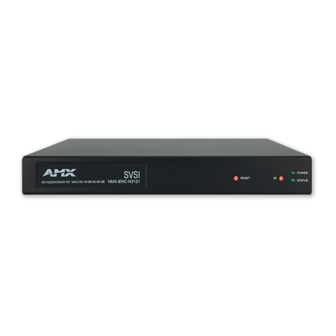
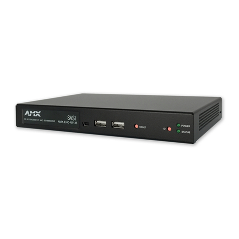
AMX NMX-ENC-1100 User manual

Instruction Manual
Video Management/Distribution
NMX-ENC
H.264 Encoder
NMX-ENC-1100
NMX-ENC-1105
Latest Release: 02/20/2014
NMX-ENC H.264 Encoder Instruction Manual

AMX Limited Warranty and Disclaimer
This Limited Warranty and Disclaimer extends only to products purchased directly from AMX or an AMX Authorized Partner which
include AMX Dealers, Distributors, VIP’s or other AMX authorized entity.
AMX warrants its products to be free of defects in material and workmanship under normal use for three (3) years from the date of
purchase, with the following exceptions:
• Electroluminescent and LCD Control Panels are warranted for three (3) years, except for the display and touch overlay compo-
nents are warranted for a period of one (1) year.
• Disk drive mechanisms, pan/tilt heads, power supplies, and MX Series products are warranted for a period of one (1) year.
• AMX lighting products are guaranteed to switch on and off any load that is properly connected to our lighting products, as long
as the AMX lighting products are under warranty. AMX also guarantees the control of dimmable loads that are properly con-
nected to our lighting products. The dimming performance or quality there of is not guaranteed, impart due to the random combi-
nations of dimmers, lamps and ballasts or transformers.
• AMX software is warranted for a period of ninety (90) days.
• Batteries and incandescent lamps are not covered under the warranty.
• AMX AutoPatch Epica, Modula, Modula Series4, Modula CatPro Series and 8Y-3000 product models will be free of defects in
materials and manufacture at the time of sale and will remain in good working order for a period of three (3) years following the
date of the original sales invoice from AMX. The three-year warranty period will be extended to the life of the product (Limited
Lifetime Warranty) if the warranty card is filled out by the dealer and/or end user and returned to AMX so that AMX receives it
within thirty (30) days of the installation of equipment but no later than six (6) months from original AMX sales invoice date. The
life of the product extends until five (5) years after AMX ceases manufacturing the product model. The Limited Lifetime Warranty
applies to products in their original installation only. If a product is moved to a different installation, the Limited Lifetime Warranty
will no longer apply, and the product warranty will instead be the three (3) year Limited Warranty.
All products returned to AMX require a Return Material Authorization (RMA) number. The RMA number is obtained from the AMX
RMA Department. The RMA number must be clearly marked on the outside of each box. The RMA is valid for a 30-day period. After
the 30-day period the RMA will be cancelled. Any shipments received not consistent with the RMA, or after the RMA is cancelled, will
be refused. AMX is not responsible for products returned without a valid RMA number.
AMX is not liable for any damages caused by its products or for the failure of its products to perform. This includes any lost profits, lost
savings, incidental damages, or consequential damages. AMX is not liable for any claim made by a third party or by an AMX Autho-
rized Partner for a third party.
This Limited Warranty does not apply to (a) any AMX product that has been modified, altered or repaired by an unauthorized agent or
improperly transported, stored, installed, used, or maintained; (b) damage caused by acts of nature, including flood, erosion, or earth-
quake; (c) damage caused by a sustained low or high voltage situation or by a low or high voltage disturbance, including brownouts,
sags, spikes, or power outages; or (d) damage caused by war, vandalism, theft, depletion, or obsolescence.
This limitation of liability applies whether damages are sought, or a claim is made, under this warranty or as a tort claim (including
negligence and strict product liability), a contract claim, or any other claim. This limitation of liability cannot be waived or amended by
any person. This limitation of liability will be effective even if AMX or an authorized representative of AMX has been advised of the
possibility of any such damages. This limitation of liability, however, will not apply to claims for personal injury.
Some states do not allow a limitation of how long an implied warranty last. Some states do not allow the limitation or exclusion of inci-
dental or consequential damages for consumer products. In such states, the limitation or exclusion of the Limited Warranty may not
apply. This Limited Warranty gives the owner specific legal rights. The owner may also have other rights that vary from state to state.
The owner is advised to consult applicable state laws for full determination of rights.
EXCEPT AS EXPRESSLY SET FORTH IN THIS WARRANTY, AMX MAKES NO OTHER WARRANTIES, EXPRESSED OR
IMPLIED, INCLUDING ANY IMPLIED WARRANTIES OF MERCHANTABILITY OR FITNESS FOR A PARTICULAR PURPOSE. AMX
EXPRESSLY DISCLAIMS ALL WARRANTIES NOT STATED IN THIS LIMITED WARRANTY. ANY IMPLIED WARRANTIES THAT
MAY BE IMPOSED BY LAW ARE LIMITED TO THE TERMS OF THIS LIMITED WARRANTY. EXCEPT AS OTHERWISE LIMITED
BY APPLICABLE LAW, AMX RESERVES THE RIGHT TO MODIFY OR DISCONTINUE DESIGNS, SPECIFICATIONS, WARRAN-
TIES, PRICES, AND POLICIES WITHOUT NOTICE.
Table of Contents
i
Instruction Manual - NMX-ENC 2.64 Encoder
Table of Contents
Overview ............................................................................................................1
Specifications............................................................................................................ 1
Minimum Performance Specifications ....................................................................... 2
Mounting the Encoder .............................................................................................. 3
Wiring and Device Connections ..........................................................................5
Overview .................................................................................................................. 5
Front Panel Components .......................................................................................... 5
LEDs ................................................................................................................................ 5
AUDIO IN ........................................................................................................................ 6
USB.................................................................................................................................. 6
ID..................................................................................................................................... 7
Rear Panel Components............................................................................................ 8
SDI................................................................................................................................... 8
MULTI FORMAT VIDEO INPUTS...................................................................................... 9
AUDIO ........................................................................................................................... 10
VIDEO PASS THRU ........................................................................................................ 10
KEYPAD......................................................................................................................... 11
INDICATORS ................................................................................................................. 11
USB................................................................................................................................ 12
LAN 10/100................................................................................................................... 12
PWR............................................................................................................................... 13
Preparing Captive Wires ............................................................................................... 13
Wiring a Power Connection........................................................................................... 13
Cable Details and Pinout Information ...............................................................15
Overview ................................................................................................................ 15
DVI-D Male to DVI-D Male Single-Link Cable.......................................................... 16
DVI-to-DVI Cable Pinout Information ............................................................................ 16
DVI-A Male to 5-BNC Male Cable ........................................................................... 17
DVI-to-5-BNC Cable Pinout Information........................................................................ 17
DVI-A Male to Triple RCA Male Cable .................................................................... 18
DVI-to-Triple RCA Cable Pinout Information ................................................................. 18
DVI-A Male to S-Video Male Cable ......................................................................... 19
DVI-to-S-Video Cable Pinout Information...................................................................... 19
DVI-A Male to HD15 (VGA) Male Adapter .............................................................. 20
DVI-to-VGA Cable Pinout Information........................................................................... 20
Web Configuration ...........................................................................................23
NMX-ENC WebConsole .......................................................................................... 23

ii Instruction Manual - NMX-ENC 2.64 Encoder
Table of Contents
Accessing the WebConsole..................................................................................... 23
Retrieving the IP Address of the Encoder ..................................................................... 23
WebConsole Interface ............................................................................................ 24
Accessing the WebConsole ........................................................................................... 24
Encoder Controls........................................................................................................... 25
Encoding ....................................................................................................................... 26
Streaming...................................................................................................................... 28
Networking ................................................................................................................... 29
System Management..................................................................................................... 30
Updating Firmware ....................................................................................................... 30
NetLinx.......................................................................................................................... 31
Programming ....................................................................................................33
Overview ................................................................................................................ 33
SEND_COMMANDS................................................................................................ 33
Encoding Commands..................................................................................................... 33
?AUDIN_FORMAT .................................................................................................................. 33
AUDIN_FORMAT.................................................................................................................... 33
?AUDIN_SAMPLING_RATE..................................................................................................... 33
?AUDSTRM_CODEC............................................................................................................... 34
?AUDSTRM_MUTE ................................................................................................................. 34
AUDSTRM_MUTE ................................................................................................................... 34
?AUDSTRM_RATE .................................................................................................................. 34
AUDSTRM_RATE .................................................................................................................... 34
?VIDIN_FORMAT.................................................................................................................... 34
VIDIN_FORMAT ..................................................................................................................... 34
?VIDIN_RES_REF .................................................................................................................... 35
?VIDSTRM_BURST .................................................................................................................. 35
VIDSTRM_BURST.................................................................................................................... 35
?VIDSTRM_CODEC ................................................................................................................ 35
?VIDSTRM_FRAME................................................................................................................. 35
VIDSTRM_FRAME................................................................................................................... 35
?VIDSTRM_GOP ..................................................................................................................... 35
VIDSTRM_GOP....................................................................................................................... 36
?VIDSTRM_PROFILE............................................................................................................... 36
VIDSTRM_PROFILE................................................................................................................. 36
?VIDSTRM_RATE .................................................................................................................... 36
VIDSTRM_RATE...................................................................................................................... 36
?VIDSTRM_RATE_CTRL .......................................................................................................... 36
VIDSTRM_RATE_CTRL ............................................................................................................ 36
Streaming Commands ................................................................................................... 37
?STRM_FORMAT .................................................................................................................... 37
STRM_FORMAT...................................................................................................................... 37
?VIDSTRM .............................................................................................................................. 37
VIDSTRM ................................................................................................................................ 37
?VIDSTRM_RES ...................................................................................................................... 37
VIDSTRM_RES ........................................................................................................................ 37
?VIDSTRM_EN........................................................................................................................ 38
VIDSTRM_EN.......................................................................................................................... 38

Table of Contents
iii
Instruction Manual - NMX-ENC 2.64 Encoder
?VIDSTRM_IP.......................................................................................................................... 38
VIDSTRM_IP ........................................................................................................................... 38
?VIDSTRM_PORT.................................................................................................................... 38
VIDSTRM_PORT ..................................................................................................................... 38
?VIDSTRM_MC_EN................................................................................................................. 38
VIDSTRM_MC_EN .................................................................................................................. 38
?VIDSTRM_MC_IP .................................................................................................................. 39
VIDSTRM_MC_IP .................................................................................................................... 39
?VIDSTRM_MC_PORT ............................................................................................................ 39
VIDSTRM_MC_PORT .............................................................................................................. 39
?VIDSTRM_MC_TTL................................................................................................................ 39
VIDSTRM_MC_TTL.................................................................................................................. 39
?VIDSTRM_STATUS ................................................................................................................ 39
Status Commands.......................................................................................................... 40
?DISABLE_SWITCH................................................................................................................. 40
DISABLE_SWITCH .................................................................................................................. 40
?RELAY_CTRL......................................................................................................................... 40
RELAY_CTRL........................................................................................................................... 40
?VIDIN_HDCP......................................................................................................................... 40
VIDIN_HDCP .......................................................................................................................... 40
?VIDIN_STATUS ..................................................................................................................... 41
Appendix A - Input Resolutions ........................................................................43
Available Pixel Display and Refresh Rates .............................................................. 43
Supported Input Video Resolutions............................................................................... 43
Composite and S-Video Supported Input Resolutions................................................... 43
Component Video Supported Input Resolutions ........................................................... 44
SDI Supported Input Resolutions .................................................................................. 44
Appendix B - Output Resolutions .....................................................................45
Available Scaled Output Resolutions ...................................................................... 45
DVI, HDMI, and VGA Supported Output Video Resolutions ......................................... 45
Composite and S-Video Supported Output Resolutions ............................................... 45
Component Video Supported Output Resolutions........................................................ 46
Recommended Bit Rates for Output Resolutions .......................................................... 46

iv Instruction Manual - NMX-ENC 2.64 Encoder
Table of Contents

Overview
1
Instruction Manual - NMX-ENC H.264 Encoder
Overview
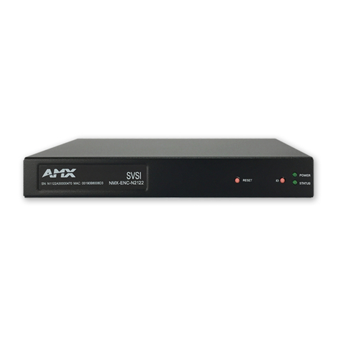
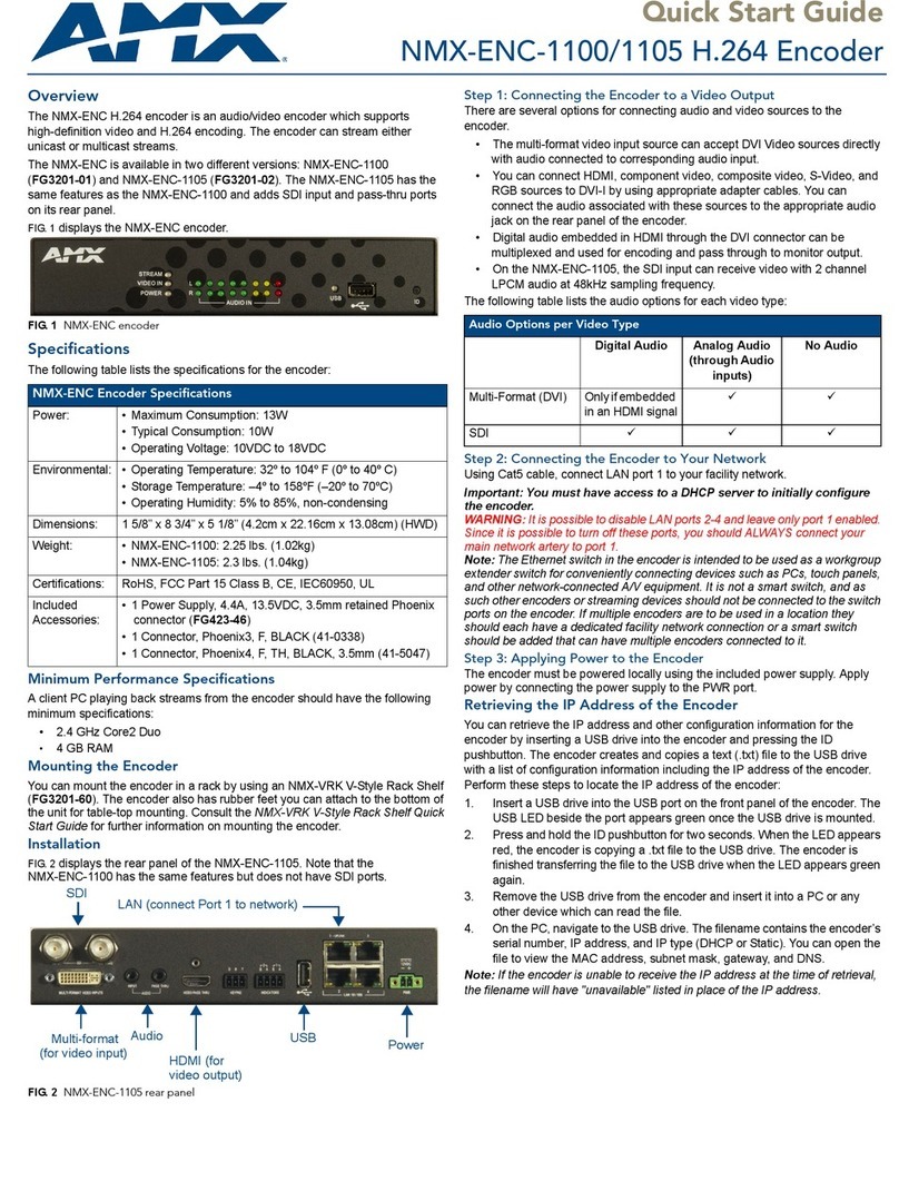
The NMX-ENC H.264 encoder is an audio/video encoder which supports high-definition video and H.264 encoding
from sources including PCs, cameras, and set-top boxes. The encoder can stream either unicast and multicast streams.
The NMX-ENC is available in two different versions: NMX-ENC-1100 (FG3201-01) and NMX-ENC-1105
(FG3201-02). The NMX-ENC-1105 has the same features as the NMX-ENC-1100 and adds SDI input and pass-thru
ports on its rear panel.
FIG. 1 NMX-ENC H.264 encoder
Specifications
The following table lists the specifications for the NMX-ENC H.264 encoder:
NMX-ENC H.264 Encoder Specifications
Active Power Requirements
Power Connector: 1 2-pin 3.5mm locking Phoenix connector
Power Capabilities: • Maximum Current Draw: 13W
• Typical Current Draw: 10W
• Operating Voltage: 10VDC to 18VDC
Front Panel Components
LEDs: All LEDs appear in green (active) or red (alarm state).
• STREAM - shows streaming status
• VIDEO IN - notes video input status
• POWER - notes power and alarm state
• USB - notes data copying state
See the LEDs section on page 5 for more information.
AUDIO IN: 2 sets of AUDIO IN LEDs indicating the signal strength of the audio input with
separate sets of indicators for the left (L) and right (R) channels. See the
AUDIO IN section on page 6 for more information.
USB: 1 Type-A USB connector. The port has an LED beside it which indicates the
state of sending data to a connected USB storage device. See the USB section
on page 6 for more information.
ID: 1 ID pushbutton to assign a device address to the encoder or copy a
configuration information file to a connected USB drive. See the ID section on
page 7 for more information.
Rear Panel Components
SDI: These connectors are only available on the NMX-ENC-1105.
• 1 BNC connector for video input (INPUT)
• 1 BNC connector for video output (PASS THRU)
See the SDI section on page 8 for more information.
MULTI FORMAT VIDEO
INPUTS:
1 DVI connector for multi-format video inputs. See the MULTI FORMAT VIDEO
INPUTS section on page 9 for more information.
AUDIO: • 1 3.5mm mini-phono connector for audio input (INPUT)
• 1 3.5mm mini-phono connector for audio output (PASS THRU)
See the AUDIO section on page 10 for more information.

Overview
2Instruction Manual - NMX-ENC H.264 Encoder
Minimum Performance Specifications
A client PC playing back streams from the encoder should have the following minimum specifications:
2.4 GHz Core2 Duo
4 GB RAM
NMX-ENC H.264 Encoder Specifications (Cont.)
VIDEO PASS THRU: 1 HDMI connector for video output. See the VIDEO PASS THRU section on
page 10 for more information.
KEYPAD: 1 3-pin 3.5mm Phoenix connector for RS-232 ports. See the KEYPAD section
on page 11 for more information.
INDICATORS: 1 4-pin 3.5mm relay port. The port features a 2-pin Recording port (Port 2) and
a 2-pin Streaming port (Port 1). See the INDICATORS section on page 11 for
more information.
USB: 1 Type-A USB connector. See the USB section on page 12 for more
information.
LAN 10/100: 4 RJ-45 LAN ports for network connections via Cat5 cabling.
Note: You should ALWAYS connect your main network artery to the port 1 LAN
port.
See the LAN 10/100 section on page 12 for more information.
Environmental
Temperature (Operating): 32° to 104° F (0° to 40° C)
Temperature (Storage): –4º to 158ºF (–20º to 70ºC)
Humidity (Operating): 5% to 85%, non-condensing
General
Dimensions (HWD): 1 5/8” x 8 3/4” x 5 1/8” (4.2cm x 22.16cm x 13.08cm)
Weight: • NMX-ENC-1100: 2.25 lbs. (1.02kg)
• NMX-ENC-1105: 2.3 lbs. (1.04kg)
Certifications: • RoHS
• FCC Part 15 Class B
•CE
• IEC60950
•UL
Included Accessories: • 1 Power Supply, 4.4A, 13.5VDC, 3.5mm retained Phoenix connector
(FG423-46)
• 1 NMX-ENC-1100/1105 H.264 Encoder Quick Start Guide (93-3201-01)
Optional Accessories: • CC-DVI-5BNCM DVI to 5 BNC adapter cable (FG10-2170-08)
• CC-DVI-RCA3M DVI to 3 Male RCA adapter cable for component and
composite connections (FG10-2170-09)
• CC-DVI-SVID DVI to S-Video adapter cable (FG10-2170-10)
• CC-DVIM-VGAF DVI to HD15 female adapter cable (FG10-2170-13)
• NMX-VRK V-Style Rack Shelf (FG3201-60)
• AVB-VSTYLE-SURFACE-MNT V-Style Single Module Surface Mount Kit
(FG1010-722)

Overview
3
Instruction Manual - NMX-ENC H.264 Encoder
Mounting the Encoder
You can mount the encoder in a rack by using an NMX-VRK V-Style Rack Shelf (FG3201-60). In addition to the
encoder, you can also use wire ties to mount the encoder’s power supply on the rack shelf. The encoder also has rubber
feet you can attach to the bottom of the unit for table-top mounting.
FIG. 2 NMX-VRK V-Style Rack Shelf
Perform these steps to mount the encoder using the NMX-VRK Rack Shelf:
1. Invert the encoder and the rack shelf for ease of installation.
2. Attach the rack shelf to the bottom of the encoder using the #4-40 3/16 inch undercut flat head screws (provided).
Insert the screws through the underside of the rack shelf and into the holes on the bottom of the encoder. Note that
only two screws are required.
3. Install the rack shelf in a standard EIA 19 in. (48.26 cm) rack and secure with rack-mounting screws.
4. (This step is optional.) Attach fill plates using the #4-40 3/16 inch undercut flat head screws (provided). Be sure to
use the screw holes closest to the front of the tray.
5. Use wire ties (not provided) to mount the power supply to the rear section of the rack shelf. This step is optional.

Overview
4Instruction Manual - NMX-ENC H.264 Encoder

Wiring and Device Connections
5
Instruction Manual - NMX-ENC H.264 Encoder
Wiring and Device Connections
Overview
This section describes the front and rear panel components for the NMX-ENC-1100 and NMX-ENC-1105. Wiring
information for port connectors is listed in each connector’s corresponding section.
Front Panel Components
The following section lists the components on the front panel of the NMX-ENC encoder.
FIG. 3 NMX-ENC (front panel)
LEDs
All LEDs appear in green or red, and in solid or blinking states. Consult the LED States table on page 6 for more
information.
STREAM - shows streaming status
VIDEO IN - notes video input status
POWER - notes power and alarm state
USB - notes file copying state
Note: The LEDs can be dimmed by selecting an option in the WebConsole pages. See the System Management section on
page 30 for more information.
FIG. 4 displays the LEDs on the front panel.
FIG. 4 Front panel LEDs
LEDs Audio signal USB ID
pushbutton
strength indicators

Wiring and Device Connections
6Instruction Manual - NMX-ENC H.264 Encoder
Consult the following table for the meaning of each LED indicator:
AUDIO IN
The audio signal strength indicators show the signal strength of the selected audio source. The encoder has separate
indicators for the left and right channels. The indicators are updated every half second. FIG. 5 displays the audio signal
strength indicators.
FIG. 5 Audio Signal Strength Indicators
USB
The front panel features one Type-A USB connector for a connecting storage device and loading preset configuration
files. The port has an LED beside it which indicates the state of copying files to an attached USB drive. See the
LEDs section on page 5 for information about the LED indicator. FIG. 6 displays the USB port and LED indicator.
FIG. 6 USB port
Note: You can only retrieve information about IP configuration for the encoder from the front panel USB port. It is not
possible to retrieve IP configuration information by using the rear panel USB port.
The front USB port can only be used to retrieve encoder configuration information. A future firmware update will add
support for additional features that utilize both USB ports.
Note: The encoder is capable of simultaneously copying to devices connected to the front and rear panel.
LED States
LED OFF Green Blinking Green Red Blinking Red
STREAM Not streaming Streaming in
progress
N/A Streaming active
and there are one
or more streaming
errors
The streaming
engine has
stopped.
VIDEO IN No video signal of
the selected
format present
Video signal of the
format is present
and synchronized
Unknown Signal.
This signifies that
the selected
format does not
match the
detected format.
While actively
streaming, an
issue with the
video signal
occurred.
An encrypted
video signal is
being used as the
video input.
POWER No power applied Power applied and
there are no
system hardware
errors
System is booting Power applied and
there are one or
more system
hardware errors
Network failure or
failure to retrieve
IP address.
USB No device
attached.
Attached drive can
be removed
without damaging
its contents.
N/A Data is being
written to the
attached device.
Do not remove the
device.
N/A

Wiring and Device Connections
7
Instruction Manual - NMX-ENC H.264 Encoder
ID
The front panel features an ID pushbutton which allows you to retrieve the IP address and other configuration
information for the encoder. You can retrieve this information by inserting a USB drive into the encoder and pressing the
ID pushbutton. The encoder creates and copies a text (.txt) file to the USB drive with a list of configuration information
including the IP address of the encoder.
Note: When a USB drive is attached to the encoder, the ID pushbutton is limited to only retrieving IP address
information. You cannot use the ID pushbutton with Identity Mode in NetLinx Studio unless there is no USB drive
present.
FIG. 7 displays the ID pushbutton.
FIG. 7 ID pushbutton
The ID pushbutton performs as follows:
To use in conjunction with the ID Mode feature in NetLinx Studio, press the button once to assign a device
address to the device.
To retrieve the configuration information about the device, press and hold the button to write the
configuration file to a USB drive connected to one of the front panel USB ports.
Note: Writing the configuration file to the USB drive can only occur once per drive insertion. If you need the encoder to
copy the file another time, you must remove the USB drive and insert it again into the USB port on the front panel.

Wiring and Device Connections
8Instruction Manual - NMX-ENC H.264 Encoder
Rear Panel Components
The following section lists the components on the rear panel of the encoder. FIG. 8 displays the rear panel of the
NMX-ENC-1100.
FIG. 8 NMX-ENC-1100 (rear panel)
FIG. 9 displays the rear panel of the NMX-ENC-1105.
FIG. 9 NMX-ENC-1105 (rear panel)
SDI
NMX-ENC-1105 model encoders feature two SDI connectors for video input/output. The SDI input can receive HDMI
non-HDCP video with 2 channel LPCM audio at 48 kHz sampling frequency. These ports support SD-SDI and HD-SDI.
The SDI connectors are as follows:
1 BNC connector for video input (INPUT)
1 BNC connector for video output (PASS THRU)
FIG. 10 SDI connectors
For a list of supported input resolutions for the SDI ports, see the SDI Supported Input Resolutions section on page 44.
DVI AUDIO HDMI RS-232 RELAYS
USB LAN (connect Port 1 to network)
POWER
(for video
output)
(for video
input)
SDI

Wiring and Device Connections
9
Instruction Manual - NMX-ENC H.264 Encoder
MULTI FORMAT VIDEO INPUTS
The encoder features one DVI connector for video input. There are several options for connecting audio and video
sources to the encoder.
The multi-format video input source can accept DVI Video sources directly with audio connected to
corresponding audio input.
You can connect HDMI, component video, composite video, S-Video, and RGB sources to DVI-I by using
appropriate adapter cables. You can connect the audio associated with these sources to the appropriate audio
jack on the rear panel of the encoder.
Digital audio embedded in HDMI through the DVI connector can be multiplexed and used for encoding and
pass through to monitor output.
On the NMX-ENC-1105, the SDI input can receive video with 2 channel LPCM audio at 48kHz sampling
frequency.
FIG. 11 displays the MULTI FORMAT VIDEO INPUTS connector.
FIG. 11 MULTI FORMAT VIDEO INPUTS connector
The following table lists the audio options for each video type:
The following table describes the pinout configuration of the MULTI-FORMAT VIDEO INPUT connector:
Audio Options per Video Type
Digital Audio Analog Audio
(through Audio
inputs)
No Audio
Multi-format (DVI) Only if embedded
in an HDMI signal
SDI
MULTI-FORMAT VIDEO INPUT Connector - Pinouts and Signals
Pin Signal Pin Signal Pin Signal
1 TMDS Data2- 9 TMDS Data1- 17 TMDS Data0-
2 TMDS Data2+ 10 TMDS Data1+ 18 TMDS Data0+
3 TMDS Data2/4 Shield 11 TMDS Data1/3 Shield 19 TMDS Data0/5 Shield
4n/c 12 n/c 20 n/c
5n/c 13 n/c 21 n/c
6 DDC Clock [SCL] 14 +5 V Power 22 TMDS Clock Shield
7 DDC Data [SDA] 15 Ground (for +5 V) 23 TMDS Clock +
8 Analog vertical sync 16 Hot Plug Detect 24 TMDS Clock -
C1 Analog Red
C2 Analog Green
C3 Analog Blue
C4 Analog Horizontal Sync
C5 Analog Ground

Wiring and Device Connections
10 Instruction Manual - NMX-ENC H.264 Encoder
AUDIO
The encoder features two audio ports for receiving and delivering audio. Audio received through the audio INPUT port
will be output through the audio PASS THRU port. The audio ports on the encoder are as follows:
1 3.5mm mini-phono connector for audio input (INPUT)
1 3.5mm mini-phono connector for audio output (PASS THRU)
Note: Any volume adjustments you want to make to an audio stream must be made at the audio source or on the audio
output.
FIG. 12 AUDIO connectors
VIDEO PASS THRU
The encoder features one HDMI connector for video output. The output replicates the video signal currently being
encoded when it comes from the multi-format connector or the SDI input connector (NMX-ENC-1105 only).
FIG. 13 VIDEO PASS THRU connector
The following table describes the pinout configuration of the VIDEO PASS THRU connector:
FIG. 14 displays the pin locations for the HDMI connector:
FIG. 14 HDMI pinouts
VIDEO PASS THRU Connector - Pinouts and Signals
Pin Signal Pin Signal
1 TMDS Data 2+ 11 TMDS Clock Shield
2 TMDS Data 2 Shield 12 TMDS Clock-
3 TMDS Data 2- 13 CEC
4 TMDS Data 1+ 14 Reserved, HEC Data
5 TMDS Data 1 Shield 15 SCL
6 TMDS Data 1- 16 SDA
7 TMDS Data 0+ 17 DDC/CEC/HEC Ground
8 TMDS Data 0 Shield 18 +5V Power (max 50mA)
9 TMDS Data 0- 19 Hot Plug Detect, HEC Data+
10 TMDS Clock+

Wiring and Device Connections
11
Instruction Manual - NMX-ENC H.264 Encoder
KEYPAD
The rear panel features one 3-pin 3.5mm Phoenix connector for RS-232 ports for controlling the encoder by keypad or
ControlPad. This connector is reserved for future use. The pin-outs for this port are as follows:
Pin 1: GND (G)
Pin 2: RXD (R)
Pin 3: TXD (T)
FIG. 15 displays the KEYPAD port.
FIG. 15 KEYPAD port
The KEYPAD port supports the following data rate and format:
Baud rate: 115200
Parity: None
Data Bits: 8
Stop Bits: 1
Software handshaking with XON & XOFF: Off
INDICATORS
The rear panel features one 4-pin 3.5mm relay port for connecting up to two independent relay devices. The port features
a 2-pin Streaming port (Port 1). Port 2 is reserved for future use. Each respective relay port is "ON" when the encoder
is streaming or recording. When a relay is "OFF", terminals A and B are open-circuit. FIG. 16 displays the
INDICATORS port.
FIG. 16 INDICATORS ports
Each relay is isolated and normally open.
Each relay is independently controlled
Each relay can switch up to 24 VDC or 28 VAC peak @ 1 A

Wiring and Device Connections
12 Instruction Manual - NMX-ENC H.264 Encoder
USB
The rear panel features one Type-A USB connector. This port is reserved for future use. FIG. 17 displays the USB
port.
FIG. 17 USB port
LAN 10/100
The encoder features four RJ-45 LAN ports for connecting to a network, digital media switcher, presentation switcher, or
video distribution device via Cat5 cabling.
FIG. 18 LAN ports
Important: You must have access to a DHCP server to initially configure the encoder.
WARNING! It is possible to disable LAN ports 2-4 and leave only port 1 enabled. Since it is possible to turn off these
ports, you should ALWAYS connect your main network artery to port 1.
Note: The Ethernet switch in the encoder is intended to be used as a workgroup extender switch for conveniently
connecting devices such as PCs, touch panels, and other network-connected A/V equipment. It is not a smart switch, and
as such other encoders or streaming devices should not be connected to the switch ports on the encoder. If multiple
encoders are to be used in a location they should each have a dedicated facility network connection or a smart switch
should be added that can have multiple encoders connected to it.
FIG. 19 provides the pinouts and signals for the LAN connector and cable.
FIG. 19 RJ-45 wiring diagram
FIG. 20 describes the blink activity for the LAN connector and cable.
FIG. 20 LAN connector / LEDs
A L
Link LED (amber) lights
when the LAN cables
are connected and
terminated correctly.
Activity LED (green)
lights when receiving or
transmitting LAN
data packets.
Other manuals for NMX-ENC-1100
2
This manual suits for next models
1
Table of contents
Other AMX Media Converter manuals

AMX
AMX MAX-CSE User manual

AMX
AMX Video Decoder MAX-CSD10 User manual

AMX
AMX FG1010-09 User manual

AMX
AMX UVC1-4K User manual

AMX
AMX Video Decoder MAX-CSD10 User manual

AMX
AMX Video Decoder MAX-CSD10 User guide

AMX
AMX NMX-ENC-1100 User manual

AMX
AMX MyTurn HPA-MYT-RX User manual

AMX
AMX AXC-MIDI Guide

AMX
AMX Line Level Converter DAS-LLC User manual