PNEUMAT Serie 103 4 CC3 AH 2L / Instruction Manual
1. PUTTING INTO SERVICE
Supervise the compressed air duct.
Use the ducts, accessories and connectors in good state and adapted to the working effective pressure
fixed by the manufacturer.
Make sure the working pressure is not superior to 6.3 bars and inferior to the recommended pressure
during the screwdriver rotation. An excessive pressure will result in an accelerated tool damage.
Make sure that the tool exhaust is not clogged and that the tool is correctly fixed to the suspension device
if you use one.
Keep a safe headway so that any tool normal reaction while functionning doesn’t bound surrounding
elements and especially during the unscrewing.
Use the most often possible carriers or reaction bars judiciously placed.
Be careful with the risk of snapping up of clothes, hairs, etc... by the rotary spindle during the putting into
service of the tool.
Remove the hands of the tool turning part.
Make sure the ensambly caracteristics correspond to the tool performances.
Do not over-charge your tool. Check and respect the power range and the recommended working
pressure.
2. GENERAL INSTRUCTIONS
Your screwdriver must be used cautioustly ; do not let it fall down or make impacts on it.
It is recommended to establish a preventive maintenance programm in order to avoid numerous repairs
and to preserve the optimal performances of your tool.
Before any intervention on the tool, switch off the tool from the compressed air network. Have your tool
repaired by a qualified technician.
The use of spare parts no sold by your provider may bring a decrease of performances and cancel all
warranties towards the manufacturer.
When the noise level at the working place is superior to 85 dB(A), it is recommended to use auditory
protectors.
Tool noise level : see the luggage lable.
Do not use a portable tool in explosive atmosphere.
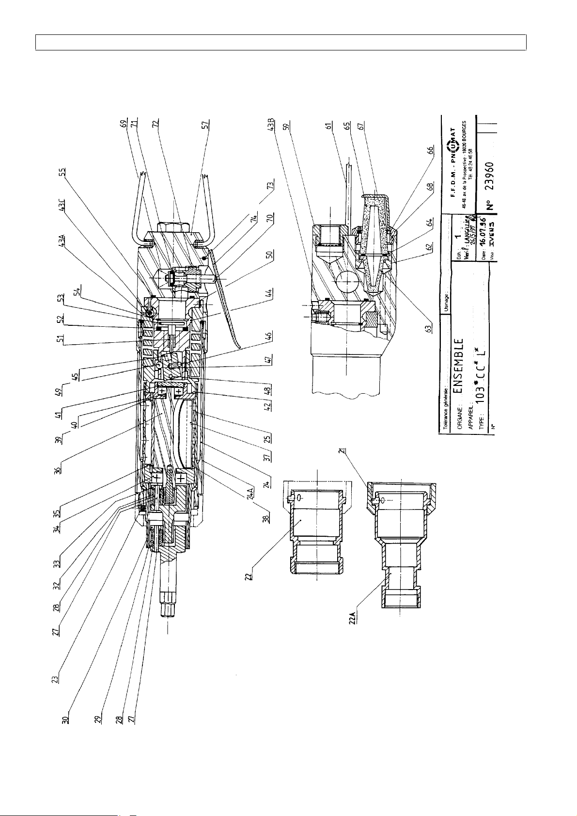
3. PNEUMAT 103 LIMITER FUNCTIONING
The mentioned marks are indicated on the exploded view.
The tightening torque at the extremity screwdriver involves a torque reaction on the motor body (25)
which tends to make the body turn in the opposite direction.
A torsion spring (43A) limits the angular bottoming proportionally to the output torque.
A cam system constituted of a ball (49) and of the cam (42) involves the central dumper displacement
(45) releasing the valve rod wich close instantaneously and stops the motor by air shut-off.
The journal (50) adjustment by the blocking screws (43B) and adjusting screws (43C) permit to vary the
spring angular bottoming amplitude.
This kind of limiter only works in the screwing sense.
The screwdrivers equipped with 103 type limiter are torque control tools with a torque adjusting system
which cuts the tool power as soon as the torque reaches a preadjusted level.
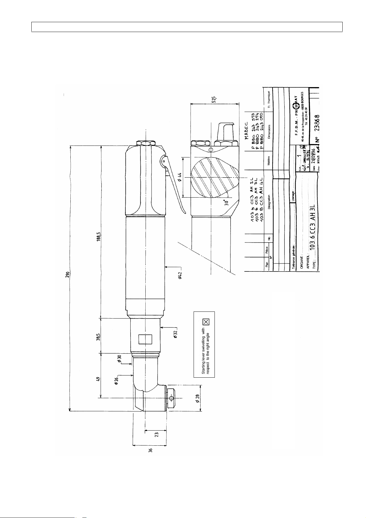
4. STARTING LEVER ORIENTATION WITH REGARD TO THE HEAD
The indexing of the angle head and of the screwdriver is made by cylinder Ø 4X4.
Untighten the nut (21).
Adjust the neck (22) by positioning the cylinder (23).
Retighten the blocking nut (tightening torque of 40Nm).