Dohrmann Enterprises DE-1008.5 User manual

Dohrmann Enterprises, Inc.
Owner’s Manual
for
DE-1008.5(-X2)
Dohrect Enject System
MY2019+
REV: 03-2021

2

3
TABLE OF CONTENTS:
Item
Page Number
Warranty Information
4
For Safe Operation
5
Winter Storage
5
Assembly & Installation
6-7
Manifold Installation (DE-1008.5X2)
8
Wiring
9-11
Header Switch Wiring
11
Plumbing
12
Flowmeter Plumbing
13
Discharge Bracket, Placement &
Installation
14-15
Calibration
16
Pumping Tube Selection, Installation &
Replacement
17-18
Operation & Calibration
19, 21
Calibration Charts
20
Troubleshooting
22-24
DE-1008.5 Parts Breakdown
25-29
For additional Calibration, Maintenance and Troubleshooting help, please give us a call or
check out our videos, which can be found at: www.DohrmannEnterprises.com/videos.

4
WARRANTY
Dohrmann Enterprises, Inc. will repair or replace any applicator part(s) that are found to be
defective within one year from the original date of purchase, except for wear parts (pumping
tubes). Defective parts must be returned to Dohrmann Enterprises, Inc. within 30 days of
failure with shipping and handling fees prepaid.
NOTE: Failure to follow proper installation and maintenance instructions found in the
Owner’s Manual will VOID all warranty.
This warranty shall not be interpreted to render Dohrmann Enterprises, Inc. liable for injury or
damages of any kind, direct, consequential, or contingent, to person or property.
Furthermore, this warranty does not extend to loss of crop, losses caused by delays or any
expense, prospective profits, or any other reason. Dohrmann Enterprises, Inc. shall not be
liable for any recovery greater in amount than the cost of report of defects in workmanship.
Defective parts caused by freight damage must be reported to the freight company by
the receiver.
SP-2L Speed Control Warranty Information:
•Opening case voids warranty
•Cutting off factory plugs or wires voids warranty
•3-year limited warranty against manufacturer defects begins on date of purchase from
Dohrmann Enterprises, Inc.
•Years 1 and 2 –Warranty exchange
oA deposit is made for new controller and return ground shipping costs.
oA refund is given if determined to be covered under warranty.
•Year 3 –Repair
oCustomer sends in controller; we cover warranted repairs and return ground
shipping.
•For customers outside of the United States, controllers under warranty must first be
sent in to Dohrmann Enterprises, and upon our findings, we will replace or repair if
considered under warranty.

5
FOR SAFE OPERATION
1. Read and follow all instructions before attempting to install or start this equipment.
2. Do not attempt to apply any chemical through equipment until you read and understand
chemical safety information and application rates.
3. Before applying a chemical, read product labels.
4. Perform a safety check on equipment before each use and at regular intervals.
5. If you encounter problems, do not operate equipment, do not treat crops. Contact the
manufacturer or your dealer immediately for assistance.
WINTER STORAGE
OPTION 1: DRAIN TANK. Flush system thoroughly with clean water (minimum of five
gallons water) and run RV water system anti-freeze (pink) through the pump and hoses to
keep from freezing.
OPTION 2: Flush system thoroughly with clean water (minimum of five gallons water). Drain,
and store in a warm building.
Do not flush system with auto anti-freeze, fuel, or any petroleum-based product. This
will cause pump failure!

6
DE-1008.5 ASSEMBLY & INSTALLATION
1. Your DE-1008.5 Dohrect Enject System is shipped assembled. Carefully remove the
foam top packaging and lift the DE-1008.5 unit out of the box. Save the original box and
packaging should the applicator need to be shipped in the future.
•There are additional system components packaged inside the cooler (Pumping
Tubes, Wire Harness, SP-2L Control, Flowmeter, Hardware, etc.).
•If a DE-1008.5X2 has been ordered, the second cooler, baseplate and manifold
(inside the cooler) will be packaged in a second box.
2. Position the DE-1008.5 baseplate on the chopper’s fender in the location where you
want it installed and mark the location of the four holes on the bottom of the baseplate.
(If the DE-1008.5-X2 is being installed, be sure to also fit and mark the location of the
additional cooler and baseplate.)
•NOTE: Without the cooler on the baseplate containing the pump assembly, the
DE-1008.5 will be tippy prior to being secured to the fender. So, during
installation of the baseplate, it is recommended to place weight on the
baseplate to counterbalance the weight of the pump assembly. Failure to do
so may result in the pump unit tipping over and possibly causing damage or
injury.
3. Before drilling the holes (3/8”) and securing the baseplate(s) to the fender, you will need
to make sure there is enough clearance to allow the door of the pump enclosure to
open. Keep in mind, the door swings forward –away from the cooler –from the top and
requires 6.75” of space from the front of the enclosure.
4. Once you have finalized the location of the baseplate(s), verify the mounting holes are
located over an area safe to drill (no hydraulic hoses, electrical cables, etc.).
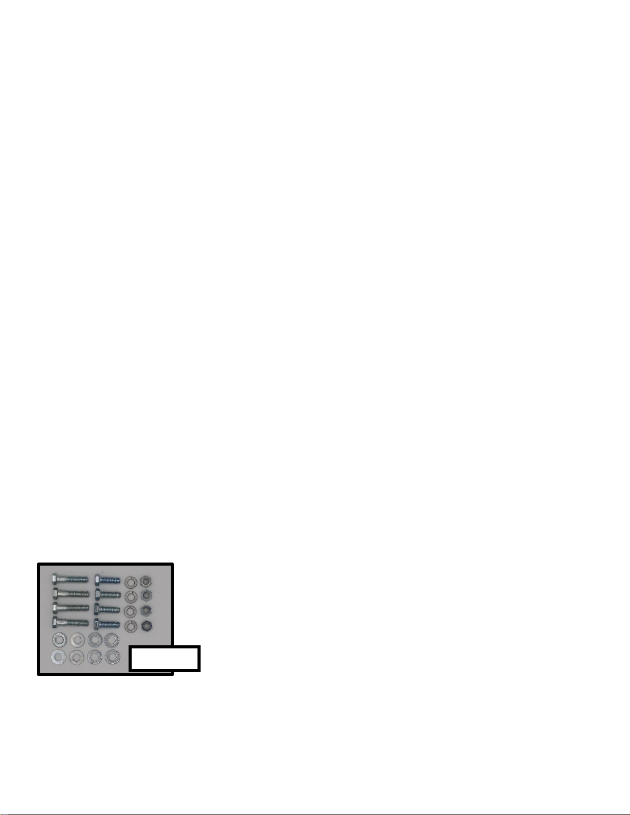
5. After you have confirmed it is safe to drill in the desired
location, drill holes in the fender through the mounting holes in the
baseplate(s) and secure the baseplate(s) with the included 5/16”
bolts, washers, and nuts, found in the hardware pack, Part #170018.
It is recommended to use a flat washer on the top, under the bolt
head, and a flat washer and Nyloc nut on the underside of the
fender.
170018

7
DE-1008.5 ASSEMBLY & INSTALLATION
CONTINUED
DE-1008.5
•If you have removed the cooler(s), you can now
place the cooler(s) back onto the baseplate(s) and
secure with the rubber straps. The rubber straps will
hook onto the handles on each side of the cooler.
•Attached the input hose to the cooler by
pressing the metal tab on the fitting (located on the
left side of the cooler valve assembly) and inserting
the fitting until it CLICKS.
•If you are installing a DE-1008.5, please skip the
directions for the manifold installation and proceed
to WIRING on Page 9.
DE-1008.5-X2
•Follow the instructions on Page 8 for the installation of the manifold.

8
1008.5-MAN TANK MANIFOLD INSTALLATION
1. Locate the area you would like to install the
manifold.
2. Before installation, give some consideration to who
will be opening and closing the valves in the field.
a. If it is the chopper operator, mount the manifold
either to the side of the cab, on the fender, or on a
baseplate where the operator can reach it.
b. If someone outside the cab will be changing the
valves, select a location that can easily be reached.
This is typically on the back edge of the fender, or on
a baseplate.
3. Once you have determined placement, you can secure
the manifold with the 5/16” bolts and Nyloc nuts enclosed.
If installing onto a baseplate. Make sure to place carriage
bolt heads on the inside of the baseplate, so the nuts are
threaded onto the bolts on the outside of the baseplate.
4. If mounting elsewhere, verify the mounting holes are
located over an area safe to drill through.
5. After you have confirmed it is all right to drill in that location, drill holes in the fender and
secure with the included 5/16” bolts and Nyloc nuts.
6. Determine which port on the assembly will control which tank. Run the hose from the
valve connection to the appropriate tank and connect the hose to the side port of the tank
valve. See picture on Page 7. Repeat this step for the other valve and cooler.
•NOTE: The direction of the valve will determine
which tank will be drawn from.
7. The final step is to connect the hose from the
bottom of the manifold valve to the short hose located
on the bottom of the pump unit. The fittings will mate
and snap together.
DRAWING
FROM TANK
ON LEFT

9
WIRING
Your DE-1008.5 is shipped with the power cord assembly, Part #364-1008.5, connected to
the SP-2L Control. The power cord assembly has two sections.
•The first section, Part #364A, will be installed
from your power supply to the SP-2L Control.
•The second section, Part #364C, will be
installed from the SP-2L Control to the pump
assembly.
•Remember, when shipped, both sections are
connected to the SP-2L Control.
SP-2L CONTROL
•Find a mounting location for the SP-2L Control. It is recommended this be in a location
within easy reach of the operator.
•Mount the controller using either the included self-tapping screws or the ¼” nuts and
bolts.
•If you are using the self-tapping screws, drill a 3/16” pilot hole in the desired screw
location.
•REMINDER: Cutting off factory plugs and/or wires, or opening case, of the SP-2L
Controller voids warranty.
FM-1008.5-LED
•On the backside of the SP-2L Control, there is a third wire lead. It is black and red with
white stripes.
•This lead will only mate up to the power cord that is attached, and part of, the
FM-1008.5-LED Flowmeter.
•FM-1008.5-LED Flowmeter will become illuminated
when power to the SP-2L is turned on, and the pump
motor is running.
•To make running the wiring easier, do not connect
until after you have installed both the SP-2L Control and
the FM-1008.5-LED Flowmeter.
•When disconnecting, ALWAYS pull on the
fittings –NOT on the wires.
364A
364C
364-1008.5

10
WIRING 1. Part #364A has bare wires and fuse holder. This end will be
connected to your 12 Volt DC power source. You may need to change the
terminals to mate up with your power source. There are additional
connections found in the electrical pack, Part #170017.
•ORANGE WIRE (w/FUSE HOLDER): The orange/red wire must be
connected to 12 volt DC positive (+). It is recommended this be connected to a
12 volt DC regulated power source, such as an in-cab power outlet, or a header
switch output. If wiring into a “header switch” output, the red wire should
be connected to the 12 volt DC (+) switched output. Only install a 3 AMP Fuse
into the fuse holder.
•BLACK WIRE: The black wire should be connected to (-) ground. If wiring
into a header switch output, the black wires should be connected to the 12 volt
DC (-) output.
2. The other end of Part #364A has a white plug on it. This plug
will mate up to the input wire connection on the SP-2L Control. On
the SP-2L Control, the wire lead will be black (-) and red (+).
3. Part #364C has a white plug on one end. Connect this output
wire connection to the SP-2L Control. On the SP-2L Control, the
wire lead will be orange (+) and blue (-).
4. From here, Part #364C will be routed to the pump assembly.
On the bottom of the pump assembly, you will find a black plug.
The black plug on the end of Part #364C will connect here. The
plug can only connect one way. Mate up the plug and insert until it
CLICKS.Additional details on Page 11.
170017
From Flowmeter to Controller: FM-1008.5-LED
From Power Source to Controller: 364A
From Pump to Controller: #364C

11
PUMP PLUG DISCONNECT
•On Part #364C there is a weather-tight latching plug which
connects to the DE-1008.5 Pump Enclosure.
•To ensure proper connection, line up the fittings and press
together until it CLICKS.
•To disconnect the power cord, press the black clip in the center,
and pull the electrical fittings apart.
•ALWAYS pull on the fittings –NOT on the wires.
•HELPFUL HINT: If it is difficult to disconnect the power cord
from the enclosure, try this:
oPush the plug portion of the power cord further into the fitting on
the enclosure. It sounds weird, but yes, plugging it in more. This
will break the weather-tight seal.
oThen, try unplugging the fittings.
HEADER SWITCH WIRING
•Your chopper must be equipped with this option and you must have the electrical
connections to mate up to the chopper’s plug. Dohrmann Enterprises, Inc. does not
stock the factory plugs for header switch connections. Header switch adapters can be
purchased from your local implement dealer.
•Dohrmann Enterprises, Inc. does offer a compatible header switch adapter plug for:
oJohn Deere 7000, 8000 & 9000 Series Self-Propelled Forage Harvesters
▪Part #190000
▪Can be used in place of John Deere Part #AZ100126
oClaas Self-Propelled Forage Harvesters
▪Part #210000
NOTE: For any wiring, be sure you have good, clean terminals, and a good connection. This
system must be connected to a 12 volt DC system. A 6 or 24 volt system WILL NOT work.
After everything is wired, if the control does not work, it has most likely been wired in reverse.
Change the red and black wires at the power source to correct this problem.

12
PLUMBING
IMPORTANT: There are NO NOZZLES or nozzle fittings shipped with your Dohrect
Enject System.These units are designed to work without nozzles. Due to the low rates per
ton, applicator through a nozzle would have a high plugging risk due to the small orifice sized
required.
To assure proper application, please pay close attention to the placement of the discharge.
Details on Pages 14-15.
FLOWMETER PLACEMENT The FM-1008.5-LED Flowmeter should be mounted
outside the cab in a location that is easy to view for
the operator. Find a desired location to mount the
FM-1008.5-LED Flowmeter.
•If mounting to a railing, attach the flowmeter
using the U-Bolt.
•If mounting to a flat surface, use the self-tapping
screws, or the 5/16” nuts and bolts provided. If using
the self-tapping screws, first drill a 3/16” pilot hole.
For most accurate readings, the flowmeter needs to
be mounted vertically.
•If adjustments are needed to assure proper
vertical installation, you can loosen the bolt on the
swivel bracket, make the adjustments, and then
re-tighten the bolt.

13
FLOWMETER PLUMBING
The FM-1008.5-LED is shipped with a 20’ length of ¼” ID X 3/8” OD hose, Part #451-20, for
the pump output. This hose will route to the FM-1008.5-LED Flowmeter and continue on from
the FM-1008.5-LED Flowmeter to the cutter head.
1. Route the ¼” ID X 3/8” ID hose, Part #451-20, from
the pump unit up to the FM-1008.5-LED Flowmeter and
cut the hose to the appropriate length for installation
into the compression fitting, Part #JACO18MPT38OD,
on the BOTTOM.Make a clean SQUARE cut to
assure proper sealing.
2. Loosen –DO NOT REMOVE - the bottom
compression nut and insert the cut end into the fitting
until it stops. Tighten the fitting to assure a proper seal.
Hand tightening is usually fine.
3. Loosen the TOP compression nut –DO NOT
REMOVE –and insert the cut end into the fitting until it
stops. Tighten the fitting to assure a proper seal.
Again, hand tightening is usually fine.
REMEMBER: The hose runs from the pump into the bottom fitting, then out of the
top fitting to the application point.
FLOW
IN
FROM
PUMP
FLOW
OUT
TO
DISCHARGE
#JACO18MPT38
OD

14
DISCHARGE HOSE & BRACKET
Find your desired discharge location. It should either be in front of the feed rolls, or behind
the feed rolls, but in front of the knives. Coverage tests that Dohrmann Enterprises, Inc. has
been involved in, or contributed equipment to, placed the discharge in one of these locations
with successful results. See examples of discharge locations in the pictures on the following
page. These will show mounting on the following choppers:
•Pull-Type
•Claas
•John Deere
•Krone
•New Holland
1. Determine where your discharge location will be. If you are inserting the hose through
a shield, check under it for any additional shields, shafts, or brackets that may interfere
with the product being applied directly to the feed.
2. Drill a 3/8” hole. If needed, remove any burrs from drilling.
3.Next remove the bolt and nut from the discharge
bracket.
4.Place the elbow through the hole you just drilled.
5. Now, mark the spot where the nut and bolt will be used
to secure the bracket. If you need to, remove the hose
before marking and drilling.
6. Drill the 3/8” hole, and if needed, remove any
burrs.
7. Line up the discharge bracket with the second
hole drilled.
8. Place the bolt through the top, and secure with
the nut from below.
9. If the hose was removed during drilling, put it
back in place, and route the ¼” ID X 3/8” OD hose from the FM-1008.5-LED to your
established discharge point.

15
DISCHARGE BRACKET PLACEMENT EXAMPLES
PULL-TYPE CLAAS
JOHN DEERE KRONE
NEW HOLLAND

16
DE-1008.5 CALIBRATION & PUMP TUBE SELECTION
PUMP TUBE SELECTION & CALIBRATION
There are two color coded pump tubes shipped with your applicator –Red and Blue –as indicated by
the zip ties on either end. Use the instructions below to determine which pump tube will work best
with your harvest rate and product concentration (mix rate).
DETERMINING YOUR HARVEST RATE
1: By reading across, find the weight of your load.
A. If the weight of your load is not listed, please round up to the next weight listed.
2: By reading down, find the time (in minutes) to load/unload.
B. If the exact time to load/unload is not listed, please round up to the faster time listed.
3: Moving down from your weight and over from your time, where the column and row meet is your
harvest rate in Tons per Minute.
Silage - Tons per Minute
Tons Per Load
4
6
8
10
12
14
16
18
20
22
24
26
Minutes to Load/Unload
12
0.5
0.7
0.8
1.0
1.2
1.3
1.5
1.7
1.8
2.0
2.2
11
0.5
0.7
0.9
1.1
1.3
1.5
1.6
1.8
2.0
2.2
2.4
10
0.6
0.8
1.0
1.2
1.4
1.6
1.8
2.0
2.2
2.4
2.6
9
0.7
0.9
1.1
1.3
1.6
1.8
2.0
2.2
2.4
2.7
2.9
8
0.5
0.8
1.0
1.3
1.5
1.8
2.0
2.3
2.5
2.8
3.0
3.3
7
0.6
0.9
1.1
1.4
1.7
2.0
2.3
2.6
2.9
3.1
3.4
3.7
6
0.7
1.0
1.3
1.7
2.0
2.3
2.7
3.0
3.3
3.7
4.0
4.3
5
0.8
1.2
1.6
2.0
2.4
2.8
3.2
3.6
4.0
4.4
4.8
5.2
4
1.0
1.5
2.0
2.5
3.0
3.5
4.0
4.5
5.0
5.5
6.0
6.5
3
1.3
2.0
2.7
3.3
4.0
4.7
5.3
6.0
6.7
7.3
8.0
2
2.0
3.0
4.0
5.0
6.0
7.0
8.0
9.0
1
4.0
6.0
8.0
4: Using the following chart, find your product mix rate across the top along with the range your
harvest rate falls in. This will determine which tube to install for proper application.
NOTE: Product mix rate of 100 tons/gallon is only recommended for use with products that have a
suggested rage of 2 grams per ton or less. Products with rates over 2 grams per ton are required to
mix at 50 or 25 tons per gallon. Further concentration may cause excessive product sediment build
up and will skew the flowmeter calibration.
Pump Tube Selection Chart
Mix Rate= 100 tons/gallon*
Mix Rate = 50 tons/gallon
Mix Rate = 25 tons/gallon
Minimum
Tons/Min.
Maximum
Tons/Min.
Minimum
Tons/Min.
Maximum
Tons/Min.
Minimum
Tons/Min.
Maximum
Tons/Min.
Blue Tube
1.50
4.00
0.75
2.00
0.50
1.00
Red Tube
3.00
8.50
1.50
4.25
0.75
2.00
*For products equal to or
less than 2 grams/ton.

17
DE-1008.5 PUMP TUBE INSTALLATION
AND REPLACEMENT
1. Even if the cooler
is empty, a good habit
to get into is start by
turning the cooler valve
off. When off, the valve
handle will either be
facing out towards you,
or up towards the line
from the flush bottle.
2. Turn the ¼ turn latches on the pump enclosure to
the left to release.
3. Pull the door out and away from the enclosure. It hinges at the
bottom of the door.
4. To open the pump head, lift up on the front of the
hinged pump head.
IF THIS IS A NEW INSTALLATION, PLEASE SKIP TO STEP 8
5. Press in the silver tab at the end of the pump tube and release
the one side of the pump tube.
6. Repeat this step for the other side.
DRAWING FROM
COOLER
CLOSED
DRAWING FROM
FLUSH BOTTLE

18
DE-1008.5 PUMP TUBE INSTALLATION
AND REPLACEMENT
7. Remove the pump tube.
8. Install the new pump tube by pressing in the silver tab on one of the
fittings on the bottom of the enclosure.
9. Push end of the tube into the hole until you hear it CLICK into place.
10. Stretch the tube across the pump rollers.
11. Press the silver tab on the other fitting on the bottom of the enclosure.
12. Insert the tube end into place and making sure it CLICKS into place.
13. After the tube is securely in place, verify the tube is centered over the
rollers, adjust if needed, and close the pump lid.
14. Close the pump enclosure door.
15. Lastly, turn the ¼ turn latches to the right.
16. DONE!
NOTE: Double check tubes are securely in place, failure to do so may result in
product pumping inside the enclosure causing NON-WARRANTY damage.
Part Number: 1008.5-PT-BL = 1008.5 Series
(Dohrect Enject) Pumping Tube –BLUE
Part Number: 1008.5-PT-RD = 1008.5 Series
(Dohrect Enject) Pumping Tube - RED

19
OPERATION & CALIBRATION
SP-2L CONTROL
The SP-2L Control contains the system’s master on/off switch, along with a dial to control the
speed of the pump.
•ON/OFF: If your system is wired through a header switch you can turn the unit on and
allow the header switch to turn the control on and off throughout the day. When the
system is on, the red LED above the switch will illuminate when the controller is on.
•DIAL: The dial on the controller increases and decreases the speed of the pump
motor, in turn, increasing and decreasing the output of the system.
oTo reduce application, turn the dial counterclockwise.
oTo increase application, turn the dial clockwise.
GENERAL OPERATION
When starting your applicator for the first time, you may notice after 15-20 minutes of run
time, the output may increase; this is normal. During the first 15-20 minutes, your pumping
tube is being broke in. Your system does not need to go through a break in period before
use. However, if you notice the increased output, simply use the SP-2L Control to readjust
back to the desired rate.
FM-1008.5-LED FLOWMETER
Your FM-1008.5-LED has calibration markings on the face of the unit, along with a ball that
floats inside the flowmeter body.
oAs you turn up your SP-2L Control (clockwise), you increase the speed of the
pump, floating the ball higher.
oThe opposite is true, if you turn down your SP-2L Control (counterclockwise), the
ball will float lower.
oWhen the SP-2L is on, the flowmeter’s LED light will illuminate.
•The markings on the left, in RED, are your output in Tons/Minute –if your product is
concentrated to a mix rate of 100 tons per gallon.
EXAMPLE: You determine you are harvesting 3.5 Tons/Minute. Simply turn the dial
on the SP-2L Control until the ball is floating on the line to the right of 3.5.
•The markings on the right, in BLACK, are your output in Ounces/Minute. This would
apply to products concentrated to a mix rate of 50 or 25 Tons/Gallon. To determine
your Ounces/Minute rates, please reference the charts found on Page 20.
EXAMPLE: You have a product concentration of 50 Tons/Gallon, and a harvest rate of
2.5 Tons/Minute. Reference the 50 Tons/Gallon Mix chart and follow the Ton/Min down
to 2.50, which equals 6.4 Ounces/Minute. Simply turn the dial on the SP-2L Control
until the ball is floating on the line, to the left of, 6.4.
NOTE: The FM-1008.5-LED Flowmeter has a calibration standard based upon
concentrations of products between 100 and 200 grams per gallon. Higher concentration
levels will provide skewed calibration, resulting in under application of product. Some
products may require the ball to float at the line, and some may require the ball to float on top
of the line for most accurate results. To assure the most accurate results, perform a
collection test.

20
CALIBRATION CHARTS
The Calibration Charts below are to provide you with the amount of total solution that you
need to apply based upon your mix rate and tonnage per minute harvested. Please note that
you may need to change your mix rate if your harvest rate drops below the lowest output of
the pump.
These charts are to be used along with the FM-1008.5 Flowmeter for calibration of your
system.
To find out how much tonnage per minute you are harvesting, please use the harvest rate
chart on Page 16.
100 Ton Per Gallon Mix
50 Ton Per Gallon Mix
25 Ton Per Gallon Mix
Tons/Min
Ounces/Min
Tons/Min
Ounces/Min
Tons/Min
Ounces/Min
1.50
1.92
0.75
1.92
0.50
2.56
2.00
2.56
1.00
2.56
0.75
3.84
2.50
3.20
1.25
3.20
1.00
5.12
3.00
3.84
1.50
3.84
1.25
6.40
3.50
4.48
1.75
4.48
1.50
7.68
4.00
5.12
2.00
5.12
1.75
8.96
4.50
5.76
2.25
5.76
2.00
10.24
5.00
6.40
2.50
6.40
5.50
7.04
2.75
7.04
6.00
7.68
3.00
7.68
6.50
8.32
3.25
8.32
7.00
8.96
3.50
8.96
KEY
7.50
9.60
3.75
9.60
Blue Tube
8.00
10.24
4.00
10.24
Blue or Red
8.50
10.88
4.25
10.88
Red Tube
Part Number: 1008.5-PT-BL = 1008.5 Series (Dohrect Enject) Pumping Tube - BLUE
Part Number: 1008.5-PT-RD = 1008.5 Series (Dohrect Enject) Pumping Tube - RED
This manual suits for next models
1
Table of contents
Popular Farm Equipment manuals by other brands

FarmTek
FarmTek 108678 manual

AIRTUG
AIRTUG TT-SD-GM Assembly & operating instructions

Arrowquip
Arrowquip Q-POWER 107 Series product manual

Monosem
Monosem NG Plus M Assembly, Adujstment and Maintenance Instructions

Johnny's Selected Seeds
Johnny's Selected Seeds 7621 U-Bar Double Wheel Hoe instruction manual

Ritchie
Ritchie EcoFount Series installation instructions

Landoll
Landoll 302D-B Operator's manual

KUHN
KUHN GA 4311 GM Assembly & operators manual

DeLaval
DeLaval FMC-IP1.1 manual

AG SHIELD
AG SHIELD LandRoller OPERATOR’S HANDBOOK AND PARTS MANUAL

Pottinger
Pottinger NOVACAT V 9200 Original operating instructions

Kuhns mfg
Kuhns mfg Tie Grabber Series owner's manual