DOLD Safemaster LG 5925 User manual

1LG 5925 / 26.02.18 de / 972
SAFEMASTER
Not-Aus-Modul
LG 5925
0262658
Datenblatt / Betriebsanleitung DEUTSCH
E. DOLD & SÖHNE KG
Postfach 1251 • 78114 Furtwangen • Deutschland
Telefon +49 7723 6540 • Fax +49 7723 654356
Original
DE
EN
FR

2LG 5925 / 26.02.18 de / 972
Inhaltsverzeichnis
Symbol- und Hinweiserklärung..........................................................................................................................................3
Allgemeine Hinweise ........................................................................................................................................................3
Bestimmungsgemäße Verwendung...................................................................................................................................3
Sicherheitshinweise...........................................................................................................................................................3
Funktionsdiagramm...........................................................................................................................................................5
Blockschaltbilder................................................................................................................................................................5
Zulassungen und Kennzeichen .........................................................................................................................................5
Anwendungen....................................................................................................................................................................5
Geräteanzeigen.................................................................................................................................................................5
Schaltbilder........................................................................................................................................................................6
Anschlussklemmen............................................................................................................................................................6
Hinweise............................................................................................................................................................................6
Technische Daten..............................................................................................................................................................6
Technische Daten..............................................................................................................................................................7
UL-Daten ...........................................................................................................................................................................7
Standardtype .....................................................................................................................................................................7
Bestellbeispiel....................................................................................................................................................................7
Vorgehen bei Störungen....................................................................................................................................................8
Wartung und Instandsetzung.............................................................................................................................................8
Kennlinie............................................................................................................................................................................8
Kennlinien..........................................................................................................................................................................8
Anwendungsbeispiele........................................................................................................................................................9
Anwendungsbeispiele......................................................................................................................................................10
Beschriftung und Anschlüsse ..........................................................................................................................................31
Maßbild (Maße in mm) ....................................................................................................................................................32
Geräteprogrammierung ...................................................................................................................................................32
Montage / Demontage der PS / PC-Klemmenblöcke ......................................................................................................32
Sicherheitstechnische Kenndaten ...................................................................................................................................33
EG-Konformitätserklärung...............................................................................................................................................34
Notizen ............................................................................................................................................................................35

3LG 5925 / 26.02.18 de / 972
Sicherheitshinweise
WARNUNG
Gefahr durch elektrischen Schlag!
Lebensgefahr oder schwere Verletzungsgefahr.
• Stellen Sie sicher, dass Anlage und Gerät während der elektrischen
Installation in spannungsfreiem Zustand sind und bleiben.
• Das Gerät darf nur für die in der mitgeltenden Betriebsanleitung / Daten-
blatt vorgesehenen Einsatzfälle verwendet werden. Die Hinweise in den
zugehörigenDokumentationenmüssenbeachtetwerden.Diezulässigen
Umgebungsbedingungen müssen eingehalten werden.
• Der Berührungsschutz der angeschlossenen Elemente und die Isolation
der Zuleitungen sind für die höchste am Gerät anliegende Spannung
auszulegen.
• Beachten Sie die VDE- sowie die örtlichen Vorschriften, insbesondere
hinsichtlich Schutzmaßnahmen.
WARNUNG
Brandgefahr oder andere thermische Gefahren!
Lebensgefahr, schwere Verletzungsgefahr oder Sachschäden.
• Das Gerät darf nur für die in der mitgeltenden Betriebsanleitung / Daten-
blatt vorgesehenen Einsatzfälle verwendet werden. Die Hinweise in den
zugehörigenDokumentationenmüssenbeachtetwerden.Diezulässigen
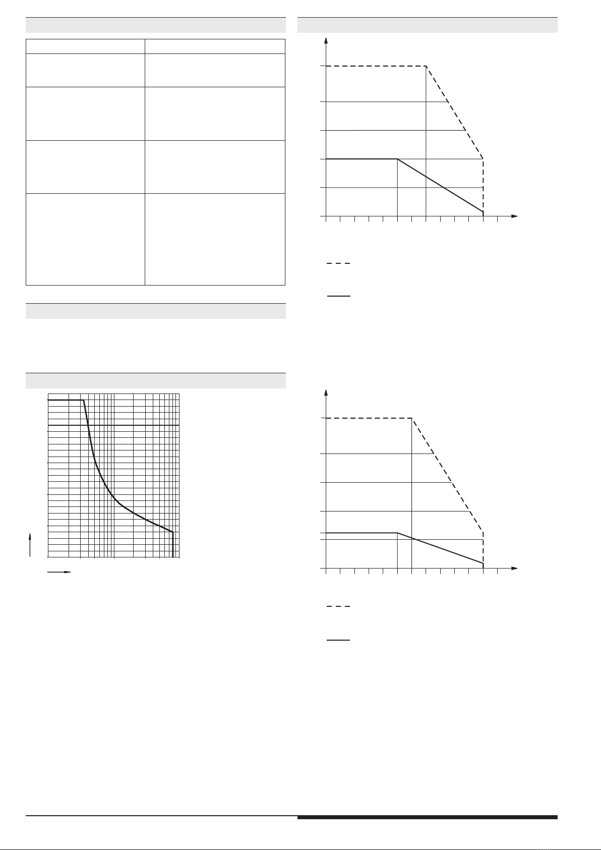
Umgebungsbedingungen müssen eingehalten werden. Insbesondere
muss die Stromgrenzkurve beachtet werden.
• Das Gerät darf nur von sachkundigen Personen installiert und in Betrieb
genommen werden, die mit dieser technischen Dokumentation und
den geltenden Vorschriften über Arbeitssicherheit und Unfallverhütung
vertraut sind.
WARNUNG
Funktionsfehler!
Lebensgefahr, schwere Verletzungsgefahr oder Sachschäden.
• Das Gerät darf nur für die in der mitgeltenden Betriebsanleitung / Daten-
blatt vorgesehenen Einsatzfälle verwendet werden. Die Hinweise in den
zugehörigenDokumentationenmüssenbeachtetwerden.Diezulässigen
Umgebungsbedingungen müssen eingehalten werden.
• Das Gerät darf nur von sachkundigen Personen installiert und in Betrieb
genommen werden, die mit dieser technischen Dokumentation und
den geltenden Vorschriften über Arbeitssicherheit und Unfallverhütung
vertraut sind.
• Montieren Sie das Gerät in einen Schaltschrank mit IP 54 oder besser;
Staub und Feuchtigkeit können sonst zur Beeinträchtigung der Funktion
führen.
WARNUNG
Installationsfehler!
Lebensgefahr, schwere Verletzungsgefahr oder Sachschäden.
• Sorgen Sie an allen Ausgangskontakten bei kapazitiven und induktiven
Lasten für eine ausreichende Schutzbeschaltung.
!
Achtung!
• Die Sicherheitsfunktion muss bei Inbetriebnahme des Gerätes ausgelöst
werden.
• Wird der Leitungsschluss beim bestromten Gerät beseitigt, schaltet
das Gerät durch.
• Der Schalter S1 darf nicht bei bestromtem Gerät betätigt werden.
• AUTOMATISCHER START !
Gemäß IEC/EN 60 204-1 Punkt 9.2.5.4.2 darf nach dem Stillsetzen im
Notfall kein automatischer Start erfolgen. Deshalb muss in den Betriebs-
arten mit automatischem Start, eine übergeordnete Steuerung einen
automatischen Start nach einem Not-Aus verhindern.
• Durch Öffnen des Gehäuses oder eigenmächtige Umbauten erlischt
jegliche Gewährleistung.
GEFAHR
GEFAHR:
Bedeutet, dass Tod oder schwere Körperverletzung eintreten
wird, wenn die entsprechenden Vorsichtsmaßnahmen nicht ge-
troffen werden.
WARNUNG
WARNUNG:
Bedeutet, dass Tod oder schwere Körperverletzung eintreten
kann, wenn die entsprechenden Vorsichtsmaßnahmen nicht
getroffen werden.
VORSICHT
VORSICHT:
Bedeutet, dass eine leichte Körperverletzung eintreten kann,
wenn die entsprechenden Vorsichtsmaßnahmen nicht getroffen
werden.
!
ACHTUNG:
Warnt vor Handlungen, die einen Schaden oder eine Fehlfunktion
des Gerätes, der Geräteumgebung oder der Hard-/Software zur
Folge haben können.
nfo
INFO:
Bezeichnet Informationen, die Ihnen bei der optimalen Nutzung
des Produktes behilflich sein sollen.
Die hier beschriebenen Produkte wurden entwickelt, um als Teil einer
Gesamtanlage oder Maschine sicherheitsgerichtete Funktionen zu über-
nehmen. Ein komplettes sicherheitsgerichtetes System enthält in der
Regel Sensoren, Auswerteeinheiten, Meldegeräte und Konzepte für si-
chere Abschaltungen. Es liegt im Verantwortungsbereich des Herstellers
einer Anlage oder Maschine die korrekte Gesamtfunktion sicherzustellen.
DOLD ist nicht in der Lage, alle Eigenschaften einer Gesamtanlage oder
Maschine, die nicht durch DOLD konzipiert wurde, zu garantieren. Das
Gesamtkonzept der Steuerung, in die das Gerät eingebunden ist, ist vom
Benutzer zu validieren. DOLD übernimmt auch keine Haftung für Empfeh-
lungen, die durch die nachfolgende Beschreibung gegeben bzw. impliziert
werden. Aufgrund der nachfolgenden Beschreibung können keine neuen,
über die allgemeinen DOLD-Lieferbedingungen hinausgehenden Garan-
tie-, Gewährleistungs- oder Haftungsansprüche abgeleitet werden.
Allgemeine Hinweise
Symbol- und Hinweiserklärung
Installation nur durch Elektrofachkraft!
Nicht im Hausmüll entsorgen!
Das Gerät ist in Übereinstimmung mit den national gültigen
Vorgaben und Bestimmungen zu entsorgen.
Aufbewahren für späteres Nachschlagen
Um Ihnen das Verständnis und das Wiederfinden bestimmter Textstellen
und Hinweise in der Betriebsanleitung zu erleichtern, haben wir wichtige
Hinweise und Informationen mit Symbolen gekennzeichnet.
Vor der Installation, dem Betrieb oder der Wartung des Gerätes
muss diese Anleitung gelesen und verstanden werden.
Bestimmungsgemäße Verwendung
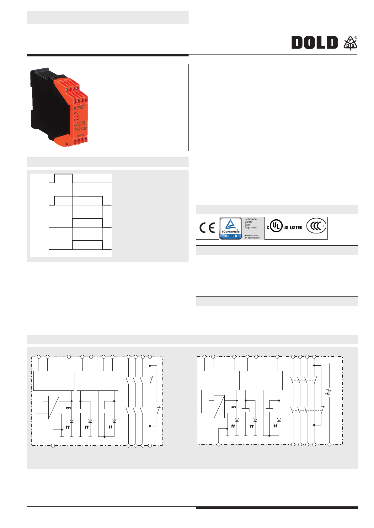
Das LG 5925 dient dem sicherheitsgerichteten Unterbrechen eines Sicher-
heitsstromkreises. Es kann zum Schutz von Personen und Maschinen in
Anwendungen mit Not-Halt-Tastern und Schutztüren verwendet werden.
Bei bestimmungsgemäßer Verwendung und Beachtung dieser Anleitung
sind keine Restrisiken bekannt. Bei Nichtbeachtung kann es zu Personen-
und Sachschäden kommen.

4LG 5925 / 26.02.18 de / 972

5LG 5925 / 26.02.18 de / 972
0243284
• entspricht
-Performance Level (PL) e und Kategorie 4 nach EN ISO 13849-1
-SIL-Anspruchsgrenze (SIL CL) 3 nach IEC/EN 62061
-Safety Integrity Level (SIL) 3 nach IEC/EN 61508 und IEC/EN 61511
• nach EN 50156-2 für Feuerungsanlagen
• Ausgang: max. 4 Schließer, siehe Kontaktbestückung
• LG 5925.54: 1 Halbleiter-Meldeausgang
• 1- oder 2-kanalige Beschaltung
• Leitungsschlusserkennung am Ein-Taster
• Aktivierung über die Ein-Taste oder automatische Ein-Funktion,
Schalter S2
• mit oder ohne Querschlusserkennung im Not-Aus-Steuerkreis, Schalter S1
• LG 5925.54: mit Querschlusserkennung im Not-Aus-Steuerkreis
• Betriebszustandsanzeige
• LED-Anzeigen für Kanal 1, 2 und Netz
• Leiteranschluss: auch 2 x 1,5 mm2Litze mit Hülse und
Kunststoffkragen, oder
2 x 2,5 mm2massiv DIN 46 228-1/-2/-3/-4
• wahlweise auch mit steckbaren Anschlussblöcken für schnellen
Geräteaustausch, optional
- mit Schraubklemmen
- oder mit Federkraftklemmen
• 22,5 mm Baubreite
Ein-Taster
Not-Aus
K1
K2
M8574 Schutz von Personen und Maschinen
• Not-Aus-Schaltungen von Maschinen
• Überwachung von Schiebeschutzgittern
• Einsatz in Feuerungsanlagen im Dauerbetrieb nach EN 50156-1
• zur Gefahrenabschaltung der gesamten Brennstoffzufuhr in
Feuerungsanlagen nach EN 50156-1 Abschnitt 10.5.5.2
LED Netz: leuchtet bei anliegender
Betriebsspannung
LED K1/K2: leuchtet bei bestromten Relais
K1 und K2
A1(+)A2(-) S11 S12 S22 S33 S34 33 412313
M8575 S21 34 422414
K2
K2
K1
Netz
24V K1
K1K2
Überspannung- und
Kurzschlußschutz
Überwachungs-
Logik
LG 5925
A1(+)A2(-) S11 S12 S22 S34 33 41
K1/K2
+
2313
M9753_a S21 34 42 582414
K2
K2
K1
Netz
24V K1
K1K2
Überspannung- und
Kurzschlußschutz
Überwachungs-
Logik
LG 5925.54
A025518
Canada / USA
Funktionsdiagramm
Zulassungen und Kennzeichen
Anwendungen
Geräteanzeigen
Blockschaltbilder
Sicherheitstechnik
SAFEMASTER
Not-Aus-Modul
LG 5925
Alle Angaben in dieser Liste entsprechen dem technischen Stand zum Zeitpunkt der Ausgabe.
Technische Verbesserungen und Änderungen behalten wir uns jederzeit vor.

6LG 5925 / 26.02.18 de / 972
LG 5925.48
S33
A1
+
S11
A2
S34
13
S12
14
41
23
S21
24
42
33
S22
34
M8553
S12
S22
S33
S34
A1+ S11
A2 S21
K1
K2
13 23 33 41
14 24 34 42
LG 5925.04
S33
A1
+
S11
A2
S34
13
S12
14
43
23
S21
24
44
33
S22
34
M8552
S12
S22
S33
S34
A1+ S11
A2 S21
K1
K2
13 23 33 43
14 24 34 44
LG 5925.02
S33
A1
+
S11
A2
S34
13
S12
14
23
S21
24
S22
M8573_a
S12
S22
S33
S34
A1+ S11
A2 S21
K1
K2
13 23
14 24
58
A1
+
S11
A2
S34
13
S12
14
41
23
S21
24
42
33
S22
34
M9721
S12
S22
S34
A1+ S11
A2 S21
K1
K2
13 23 33 41 +
14 24 34 42 58
K1/K2
LG 5925.54
Eingang
Nennspannung UN:
LG 5925: AC/DC 24 V, AC 110 ... 115 V, AC 230 V
LG 5925.54: AC/DC 24 V
Spannungsbereich
AC / DC 0,9 ... 1,1 UN
AC: 0,85 ... 1,1 UN
Nennverbrauch bei UN: DC ca. 1,5 W
AC ca. 3,7 VA
Mindestausschaltdauer: 250 ms
Steuerspannung an S11 bei UN: DC 22 V bei AC- / DC-Geräten
DC 24 V bei AC-Geräten
Steuerstrom (typ.) über S12
oder S22:
LG 5925: 30 mA bei UN
LG 5925.54: 25 mA bei UN
Mindestspannung
an Klemmen S12, S22
bei aktiviertem Gerät: DC 20 V bei AC/DC-Geräten
DC 19 V bei AC-Geräten
Absicherung des Gerätes: Intern mit PTC
Überspannungsschutz: Intern durch VDR
Ausgang
Kontaktbestückung
LG 5925.02: 2 Schließer
LG 5925.04: 4 Schließer
LG 5925.03, LG 5925.48,
LG 5925.54: 3 Schließer, 1 Öffner
Die Schließer-Kontakte können für Sicherheitsabschaltungen verwendet
werden.
Der Öffner-Kontakt 41-42 ist nur als Meldekontakt verwendbar.
Ansprechzeit typ. bei UN:
Handstart: 30 ms
Automatischer Start: 350 ms
Rückfallzeit typ. bei UN:
bei Unterbrechung der
Versorgungsspannung: 150 ms bei AC-Geräten
50 ms bei DC-Geräten
bei Unterbrechung in S12, S22: 130 ms bei AC-Geräten
50 ms bei DC-Geräten
Kontaktart: Relais, zwangsgeführt
Ausgangsnennspannung: max. AC 250 V
DC: siehe Lichtbogengrenzkurve
Thermischer Strom Ith:max. 8 A pro Kontakt
siehe Summenstromgrenzkurve
LG 5925.03
S33
A1
+
S11
A2
S34
13
S12
14
41
23
S21
24
42
33
S22
34
M10536
S12
S22
S33
S34
A1+ S11
A2 S21
K1
K2
13 23 33 41
14 24 34 42
Leitungsschlusserkennung am Ein-Taster:
Ist der Ein-Taster bereits vor Anlegen der Spannung an S12, S22 ge-
schlossen oder liegt ein Leitungsschluss über dem Ein-Taster vor, lassen
sich die Ausgangskontakte nicht einschalten.
Ein Leitungsschluss über dem Ein-Taster, der nach der Aktivierung des
Gerätes aufgetreten ist, wird beim erneuten Einschaltvorgang erkannt
und das Einschalten der Ausgangskontakte verhindert.
Die Anschlussklemme S21 dient dazu, das Gerät auch in IT-Netzen mit
Isolationsüberwachung zu betreiben, sowie als Bezugspunkt zur Prüfung
der Steuerspannung und als Anschlusskontakt bei Not-Aus mit Quer-
schlusserkennung. Bei DC-Geräten wird durch Anschluss des Schutzlei-
ters an die Anschlussklemme S21 der interne Kurzschlussschutz in der
A2 (-) Leitung überbrückt. Der Kurzschlussschutz in der A1 (+) Leitung
bleibt wirksam.
Zur Einstellung der Funktionen Automatischer Start, Hand-Start und Not-
Aus mit oder ohne Querschlusserkennung sind die Schalter S1 und S2
vorgesehen. Diese Schalter befinden sich hinter der Front-Abdeckplatte
(siehe Bild Geräteprogrammierung).
Die Wahl der Betriebsart mit oder ohne Querschlusserkennung am Not-
Aus-Taster erfolgt über den Schalter S1 (außer beim LG 5925.54).Das LG
5925.54 hat immer eine Querschlusserkennung.
Der Schalter S2 dient zur Wahl von automatischem oder Hand-Start. Für
die Funktion "automatischer Start" sind außerdem die Klemmen S33 und
S34 zu überbrücken. Der Geräteanschluss ist gemäß Anwendungsbei-
spiel vorzunehmen.
Klemmenbezeichnung Signalbeschreibung
A1+ + / L
A2 - / N
S12, S22, S33, S34 Steuereingänge
S11, S21 Steuerausgänge
13, 14, 23, 24, 33, 34, 43, 44 Schließer zwangsgeführt für
Freigabekreis
41, 42 Meldeausgang zwangsgeführt
58 Halbleiter-Meldeausgang
Schaltbilder Hinweise
Technische Daten
Anschlussklemmen

7LG 5925 / 26.02.18 de / 972
Schaltvermögen
nach AC 15:
Schließer: 3 A / AC 230 V IEC/EN 60 947-5-1
Öffner: 2 A / AC 230 V IEC/EN 60 947-5-1
nach DC 13:
Schließer: 2 A / DC 24 V IEC/EN 60 947-5-1
Öffner: 2 A / DC 24 V IEC/EN 60 947-5-1
in Anlehnung an DC 13:
Schließer: 4 A / DC 24 V bei 0,1 Hz
Öffner: 4 A / DC 24 V bei 0,1 Hz
Elektrische Lebensdauer
bei 5 A, AC 230 V cos ϕ= 1: > 2,2 x 10⁵Schaltspiele
Zulässige Schalthäufigkeit: max. 1 200 Schaltspiele / h
Kurzschlussfestigkeit
max. Schmelzsicherung: 10 A gG / gL IEC/EN 60 947-5-1
Sicherungsautomat: B 6 A
Mechanische Lebensdauer: > 20 x 106Schaltspiele
Halbleiter-Meldeausgang: DC 24 V 100 mA, plusschaltend
Allgemeine Daten
Nennbetriebsart: Dauerbetrieb
Temperaturbereich
Betrieb: - 25 ... + 55 °C
Lagerung : - 40 ... + 85 °C
Betriebshöhe: < 2.000 m
Luft- und Kriechstrecken
Bemessungsstoßspannung /
Verschmutzungsgrad: 4 kV / 2 (Basisisolierung) IEC 60 664-1
EMV IEC/EN 62 061
Funkentstörung: Grenzwert Klasse B EN 55 011
Schutzart: Gehäuse: IP 40 IEC/EN 60 529
Klemmen: IP 20 IEC/EN 60 529
Gehäuse: Thermoplast mit V0-Verhalten
nach UL Subject 94
Rüttelfestigkeit: Amplitude 0,35 mm
Frequenz 10 ... 55 Hz, IEC/EN 60 068-2-6
Klimafestigkeit: 25 / 055 / 04 IEC/EN 60 068-1
Klemmenbezeichnung: EN 50 005
Leiterbefestigung: unverlierbare Plus-Minus-Klemmen-
schrauben M 3,5 Kastenklemmen mit
selbstabhebendem Drahtschutz
oder Federkraftklemmen
Schnellbefestigung: Hutschiene IEC/EN 60 715
Nettogewicht:
LG 5925, AC/DC 24 V: 210 g
LG 5925.54, AC/DC 24 V: 220 g
LG 5925, AC 230 V: 275 g
Geräteabmessungen
Breite x Höhe x Tiefe
LG 5925: 22,5 x 90 x 121 mm
LG 5925 PC: 22,5 x 111 x 121 mm
LG 5925 PS: 22,5 x 104 x 121 mm
Die Sicherheitsfunktionen des Gerätes wurden nicht durch die UL
untersucht. Die Zulassung bezieht sich auf die Forderungen des
Standards UL508,“general use applications“
Nennspannung UN:
LG 5925.02, .04, .48, .54: AC/DC 24 V, AC 110 ... 115 V
AC 230 V
Umgebungstemperatur
LG 5925.02, .04, .48, .54: - 25 … + 55 °C
Schaltvermögen
LG 5925.04
Umgebungstemperatur 35°C: Pilot duty B300
8A 250Vac Resistive
8A 24Vdc Resistive or G.P.
LG 5925.04
Umgebungstemperatur 55°C: Pilot duty B300
4A 250Vac Resistive
4A 24Vdc Resistive or G.P.
Schaltvermögen
LG 5925.02, .48, .54
Umgebungstemperatur 45°C: Pilot duty B300
8A 250Vac Resistive
8A 24Vdc Resistive or G.P.
LG 5925.02, .48, .54
Umgebungstemperatur 55°C: Pilot duty B300
6A 250Vac Resistive
6A 24Vdc Resistive or G.P.
Leiteranschluss: nur für 60°C / 75°C Kupferleiter
Feste Schraubklemme: AWG 20 - 12 Sol/Str Torque 0.8 Nm
PS-Klemme: AWG 20 - 14 Sol Torque 0.8 Nm
AWG 20 - 16 Str Torque 0.8 Nm
PC-Klemme: AWG 20 - 12 Sol/Str
nfo
Fehlende technische Daten, die hier nicht explizit angegeben
sind, sind aus den allgemein gültigen technischen Daten zu
entnehmen.
LG 5925.48/61 AC / DC 24 V
Artikelnummer: 0061919
LG 5925.54/61 AC / DC 24 V
Artikelnummer: 0064882
• Ausgang: 3 Schließer, 1 Öffner
• Nennspannung UN: AC/DC 24 V
• Baubreite: 22,5 mm
LG 5925 ._ _ _ _ /61 AC 230 V
Nennspannung
UL-Zulassung
Klemmenart
ohne Bezeichnung:
Klemmenblöckenichtabnehmbar
mit Schraubklemmen
PC (plug in cage clamp):
abnehmbare Klemmenblöcke
mit Federkraftklemmen
PS (plug in screw):
abnehmbare Klemmenblöcke
mit Schraubklemmen
Kontaktbestückung
Type
Technische Daten
Standardtype
UL-Daten
Bestellbeispiel

8LG 5925 / 26.02.18 de / 972
Lichtbogengrenzkurve
Summenstromgrenzkurve LG 5925; AC 110 ... 115 V, AC 230 V
Summenstromgrenzkurve LG 5925; AC/DC 24 V
M8887_d
50
I
2
(A)
2
150
200
256
100
010 20 30 40 6050 T(
C)
°
- Strom in den Kontaktpfaden
I,I,I,I
1234
I=I+I+I+I
22222
12 34
Gerät angereiht, mit Fremderwärmung
durch Geräte gleicher Last
Max. zulässiger Strom bei 55°C über
4Kontaktreihen =1A=4x1 A=4A
22 2
^
Gerät freistehend
Max. Strom bei 55°C über
4Kontaktreihen =5A=4x5 A=100A
22 2
^
M9927_a
Gerät mit 5mm Mindestabstand angereiht
Max. Strom bei 55°C über
4Kontaktreihen =1A=4x1 A=4A
22 2
^
Gerät freistehend
Max. Strom bei 55°C über
4Kontaktreihen =4A=4x4 A=64A
22 2
^
- Strom in den KontaktpfadenI,I,I,I
1234
I=I+I+I+I
22222
12 34
50
64
I
2
(A)
2
150
200
256
100
010 20 30 40 6050 T(
C)
°
00,10,3 0,513510
SchaltstromA
50
100
150
250
200
SchaltspannungVDC
M2028_e
Sicheres Abschalten,kein stehender Lichtbogen,
max. 1 Schaltspiel /s
Fehler mögliche Ursache
LED "Netz" leuchtet nicht - Versorgungsspannung nicht
angeschlossen
- Querschluss zwischen S11 und S21
LED "K1" leuchtet,
aber "K2" nicht
- Sicherheitsrelais K1 ist verschweißt
(Gerät austauschen)
- Es hat eine 1-kanalige Abschaltung
an S12 stattgefunden (Kanal an
S22 abschalten)
LED "K2" leuchtet,
aber "K1" nicht
- Sicherheitsrelais K2 ist verschweißt
(Gerät austauschen)
- Es hat eine 1-kanalige Abschaltung
an S22 stattgefunden (Kanal an
S12 abschalten)
Gerät kann nicht gestartet
werden
Handstart-Modus:
- Leitungsschluss am Ein-Taster
(Versorgungsspannung trennen und
Fehler beheben)
Auto-Start-Modus:
- S33-S34 nicht gebrückt
- Ein Sicherheitsrelais ist verschweißt
(Gerät austauschen)
- Schalter S1 hat falsche Stellung
- Das Gerät enthält keine Teile, die einer Wartung bedürfen.
- Bei vorliegenden Fehlern das Gerät nicht öffnen, sondern an den
Hersteller zur Reparatur schicken.
Vorgehen bei Störungen
Wartung und Instandsetzung
Kennlinien
Kennlinie

9LG 5925 / 26.02.18 de / 972
Einkanalige Not-Aus-Schaltung.Diese Schaltung hat keine Redundanz im
Not-Aus-Befehlsgeberkreis.
Bitte Hinweis "Geräteprogrammierung" beachten !
Schalterstellung: S1 nicht querschlusssicher
S2 Auto-Start
Geeignet bis SIL2, Performance Level d, Kat. 3
Aus
L1
M8577_b
N
Not-
Aus
A2(-)
A1(+) S11 S33 S34 S12 S22
S21
LG5925
13
14
.. ..
.. ..
Kontaktverstärkung durch externe Schütze, zweikanalig.
Bei Schaltströmen > 8 A können die Ausgangskontakte durch externe
Schütze mit zwangsgeführten Kontakten verstärkt werden. Die Funktion
der externen Schütze wird durch Einschleifen der Öffnerkontakte in den
Einschaltkreis (Klemmen S33-S34) überwacht.
Bitte Hinweis "Geräteprogrammierung" beachten !
Schalterstellung: S1 nicht querschlusssicher
S2 Handstart
Geeignet bis SIL3, Performance Level e, Kat. 4
Kontaktverstärkung durch externe Schütze mit einem Kontaktpfad ange-
steuert.
Bitte Hinweis "Geräteprogrammierung" beachten !
Schalterstellung: S1 nicht querschlusssicher
S2 Auto-Start
Geeignet bis SIL3, Performance Level e, Kat. 4
L1
M8580_c
N
Not-
Aus
A2(-)
A1(+) S11 S33 S34 S12 S22
S21
LG5925
13 23
14 24
..
..
K4
K4 K5
K5
Ein
L1
M8579_c
N
Not-
Aus
A2(-)
A1(+) S11 S33 S34 S12 S22
S21
LG5925
13
14
.. ..
.. ..
K4
K4 K5
K5
Anwendungsbeispiele

10 LG 5925 / 26.02.18 de / 972
Zweikanalige Not-Aus-Schaltung mit Querschlusserkennung.
Bitte Hinweis "Geräteprogrammierung" beachten !
Schalterstellung: S1 querschlusssicher
S2 Handstart
Geeignet bis SIL3, Performance Level e, Kat. 4
L1
M8581_b
N
Not-
Aus
A2(-)
A1(+) S11 S33 S34 S12 S22 S21
LG5925
13
14
....
....
Ein
Zweikanalige Not-Aus-Schaltung ohne Querschlusserkennung
Bitte Hinweis "Geräteprogrammierung" beachten !
Schalterstellung: S1 nicht querschlusssicher
S2 Handstart
Geeignet bis SIL3, Performance Level e, Kat. 4
L1
M8578_b
N
Not-
Aus
A2(-)
A1(+) S11 S33 S34 S12 S22
S21
LG5925
13
14
.. ..
.. ..
Ein
Zweikanalige Not-Aus-Schaltung mit Querschlusserkennung.
Bitte Hinweis "Geräteprogrammierung" beachten !
Schalterstellung: S2 Handstart
Geeignet bis SIL3, Performance Level e, Kat. 4
L1
M9759
N
Not-
Aus
A2(-)
A1(+) S11 S34 S12 S22 S21
LG5925.54
13
14
....
....
Ein
L1
M8582_c
N
A2(-)
A1(+) S11 S33 S34 S12 S22
S21
LG5925
13
14
.. ..
.. ..
Ein
Schiebeschutzgitter
geschlossen
betätigter Schließer
(Kontaktstellung: geschlossen)
Zweikanalige Überwachung eines Schiebeschutzgitters.
Bitte Hinweis "Geräteprogrammierung" beachten !
Schalterstellung: S1 nicht querschlusssicher
S2 Handstart
Geeignet bis SIL3, Performance Level e, Kat. 4
Anwendungsbeispiele
E. DOLD & SÖHNE KG • D-78114 Furtwangen
e-mail: dold-relays
@dold.com • internet: http://www.dold.com
•
Postfach 1251 • Telefon 0 77 23 / 654-0 • Telefax 0 77 23 / 654-356

11 LG 5925 / 26.02.18 en / 972
SAFEMASTER
Emergency Stop Module
LG 5925
0262658
Datasheet / Operating Instructions ENGLISH
E. DOLD & SÖHNE KG
P.O. Box 1251 • D-78114 Furtwangen • Germany
Tel: +49 7723 6540 • Fax +49 7723 654356
Translation
of the original instructions

12 LG 5925 / 26.02.18 en / 972
Contents
Symbol and Notes Statement..........................................................................................................................................13
General Notes .................................................................................................................................................................13
Designated Use...............................................................................................................................................................13
Safety Notes ....................................................................................................................................................................13
Function Diagram ............................................................................................................................................................15
Block Diagrams ...............................................................................................................................................................15
Approvals and Markings ..................................................................................................................................................15
Applications .....................................................................................................................................................................15
Indicators.........................................................................................................................................................................15
Circuit Diagrams..............................................................................................................................................................16
Connection Terminals ......................................................................................................................................................16
Notes ...............................................................................................................................................................................16
Technical Data.................................................................................................................................................................16
Technical Data.................................................................................................................................................................17
UL-Data ...........................................................................................................................................................................17
Standard Type..................................................................................................................................................................17
Ordering Example ...........................................................................................................................................................17
Troubleshooting ...............................................................................................................................................................18
Maintenance and repairs.................................................................................................................................................18
Characteristics.................................................................................................................................................................18
Application Examples ......................................................................................................................................................19
Application Examples ......................................................................................................................................................20
Labeling and connections................................................................................................................................................31
Dimensions (dimensions in mm) .....................................................................................................................................32
Setting .............................................................................................................................................................................32
Mounting / disassembly of the PS / PC-terminal blocks ..................................................................................................32
Safety Related Data ........................................................................................................................................................33
CE-Declaration of Conformity..........................................................................................................................................34
Notice ..............................................................................................................................................................................35

13 LG 5925 / 26.02.18 en / 972
Safety Notes
WARNING
Risk of electrocution!
Danger to life or risk of serious injuries.
• Disconnect the system and device from the power supply and ensure
they remain disconnected during electrical installation.
• The device may only be used for the applications described in the mu-
tually applicable operating instructions / data sheet. The notes in the
respective documentation must be heeded. The permissible ambient
conditions must be observed.
• The contact protection of the elements connected and the insulation of
the supply cables must be designed in accordance with the requirements
in the operating instructions / data sheet.
• Note the VDE and local regulations, particularly those related to protec-
tive measures.
WARNING
Risk of fire or other thermal hazards!
Danger to life, risk of serious injuries or property damage.
• The device mayonly beused for the applicationsdescribedinthemutually
applicable operating instructions / data sheet. Thenotes inthe respective
documentation must be heeded. The permissible ambient conditions
must be observed. In particular, the current limit curve must be heeded.
• The device may only be installed and put into operation by experts who
are familiar with this technical documentation and the applicable health
and safety and accident prevention regulations.
WARNING
Functional error!
Danger to life, risk of serious injuries or property damage.
• The device may only be used for the applications described in the mu-
tually applicable operating instructions / data sheet. The notes in the
respective documentation must be heeded. The permissible ambient
conditions must be observed.
• The device may only be installed and put into operation by experts who
are familiar with this technical documentation and the applicable health
and safety and accident prevention regulations.
• The unit should be panel mounted in an enclosure rated at IP 54 or
superior. Dust and dampness may lead to malfunction.
WARNING
Installation fault!
Danger to life, risk of serious injuries or property damage.
• Make sure of sufficient protection circuitry at all output contacts for
capacitive and inductive loads.
!
Attention!
• The safety function must be triggered during commissioning.
• If a line fault occurs after the voltage has been connected to S12, S22,
the unit will be activated because this line fault is similar to the normal
On-function.
• Switch S1 must not be set while device is under supply voltage.
• AUTOMATIC START !
According to IEC/EN 60 204-1 part 9.2.5.4.2 and 10.8.3 it
is not allowed
to restart automatically after emergency stop.
Therefore the machine control has to disable the automatic start
after emergency stop.
• Opening the device or implementing unauthorized changes voids any
warranty
DANGER
DANGER:
Indicates that death or severe personal injury will result if
proper precautions are not taken.
WARNING
WARNING:
Indicates that death or severe personal injury can result if
proper precautions are not taken.
CAUTION
CAUTION:
Indicates that a minor personal injury can result if proper
precautions are not taken.
!
ATTENTION:
Warns against actions that can cause damage or malfunction of the
device, the device environment or the hardware / software result.
nfo
INFO:
Referred information to help you make best use of the product.
Symbol and Notes Statement
The installation must only be done by a qualified electrican!
Do not dispose of household garbage!
The device must be disposed of in compliance with nationally
applicable rules and requirements.
To help you understand and find specific text passages and notes in the
operating instructions, we have important information and information
marked with symbols.
Before installing, operating or maintaining this device, these in-
structions must be carefully read and understood.
The product hereby described was developed to perform safety functions
as a part of a whole installation or machine. A complete safety system
normally includes sensors, evaluation units, signals and logical modules
for safe disconnections. The manufacturer of the installation or machine
is responsible for ensuring proper functioning of the whole system. DOLD
cannot guarantee all the specifications of an installation or machine that
was not designed by DOLD. The total concept of the control system into
which the device is integrated must be validated by the user. DOLD also
takes over no liability for recommendations which are given or implied in
the following description. The following description implies no modification
of the general DOLD terms of delivery, warranty or liability claims.
General Notes
Designated Use
The LG 5925 is used to interrupt a safety circuit in a safe way. It can be
used to protect people and machines in applications with e-stop buttons
and safety gates.
When used in accordance with its intended purpose and following these
operating instructions, this device presents no known residual risks. Non-
observance may lead to personal injuries and damages to property.
Storage for future reference

14 LG 5925 / 26.02.18 en / 972

15 LG 5925 / 26.02.18 en / 972
• According to
-Performance Level (PL) e and category 4 to EN ISO 13849-1
-SIL Claimed Level (SIL CL) 3 to IEC/EN 62061
-Safety Integrity Level (SIL) 3 to IEC/EN 61508 and IEC/EN 61511
• According to EN 50156-2 for furnaces
• Output: max. 4 NO contacts, see contacts
• LG 5925.54: 1 semiconductor output
• Single and 2-channel operation
• Line fault detection on On-button
• Manual restart or automatic restart, switch S2
• With or without cross fault monitoring in the E-stop loop, switch S1
• LG 5925.54: with cross fault monitoring in the E-stop loop
• LED indicator for state of operation
• LED indicator for channel 1 and 2
• Removable terminal strips
• Wire connection: also 2 x 1.5 mm2stranded ferruled, or
2 x 2.5 mm2solid DIN 46 228-1/-2/-3/-4
• As option with pluggable terminal blocks for easy exchange
of devices
- with screw terminals
- or with cage clamp terminals
• Width: 22.5 mm
0243372
Protection of people and machines
• Emergency stop circuits on machines
• Monitoring of safety gates
• Usage in furnace application in continuous operation acc. to EN 50156-1
• Safe disconnection of the complete fuel supply in furnace applications
according to EN 50156-1 section 10.5.5.2
LED "Netz": on when supply connected
LED K1/K2: on when relay K1 and K2 energized
push button ON
emergency-stop
K1
K2
M6665
LG 5925 LG 5925.54
A1(+)A2(-) S11 S12 S22 S33 S34 33 412313
M6666 S21 34 422414
K2
K2
K1
Power
24V K1
K1K2
Overvoltage and
short circuit prot. Monitoring logic
A1(+)A2(-) S11 S12 S22 S34 33 412313
M9754 S21 34 422414
K2
K2
K1
Power
24V K1
K1K2
Overvoltage and
short circuit prot. Monitoring logic
K1/K2
+
58
A025518
Canada / USA
Function Diagram
Approvals and Markings
Applications
Indicators
Block Diagrams
Safety Technique
SAFEMASTER
Emergency Stop Module
LG 5925
All technical data in this list relate to the state at the moment of edition. We reserve the right for
technical improvements and changes at any time.

16 LG 5925 / 26.02.18 en / 972
LG 5925.48
S33
A1
+
S11
A2
S34
13
S12
14
41
23
S21
24
42
33
S22
34
M8553
S12
S22
S33
S34
A1+ S11
A2 S21
K1
K2
13 23 33 41
14 24 34 42
LG 5925.04
S33
A1
+
S11
A2
S34
13
S12
14
43
23
S21
24
44
33
S22
34
M8552
S12
S22
S33
S34
A1+ S11
A2 S21
K1
K2
13 23 33 43
14 24 34 44
LG 5925.02
S33
A1
+
S11
A2
S34
13
S12
14
23
S21
24
S22
M8573_a
S12
S22
S33
S34
A1+ S11
A2 S21
K1
K2
13 23
14 24
58
A1
+
S11
A2
S34
13
S12
14
41
23
S21
24
42
33
S22
34
M9721
S12
S22
S34
A1+ S11
A2 S21
K1
K2
13 23 33 41 +
14 24 34 42 58
K1/K2
LG 5925.54
LG 5925.03
S33
A1
+
S11
A2
S34
13
S12
14
41
23
S21
24
42
33
S22
34
M10536
S12
S22
S33
S34
A1+ S11
A2 S21
K1
K2
13 23 33 41
14 24 34 42
Line fault detection on On-button:
The line fault detection is only active when S12 and S22 are switched
simultaneously. If The On-button is closed before S12, S22 is connected
to voltage (also when line fault across On-Button), the output contacts will
not close. A line fault across the On-button which occurred after activation
of the relay, will be detected with the next activation and the output con-
tacts will not close.
The terminal S21 permits the operation of the device in IT-systems with
insulation monitoring, serves as a reference point for testing the control
voltage and is used to connect the E-stop loop when cross fault moni-
toring is selected.
Connecting the terminal S21 to the protective ground bridges the internal
short-circuit protection of Line A2 (-). The short-circuit protection of line
A1 (+) remains active.
To alter the functions automatic start - manual start and with or without
cross fault monitoring, the switches S1 and S2 are used. These are loca-
ted behind the front cover (see unit programming).
The setting with or without cross fault monitoring on E-stop buttons is
made with S1 (not for LG 5925.54). The LG 5925.54 has always cross
fault monitoring.
S2 is used to change between automatic an manual restart. On automatic
start also the terminals S33 - S34 have to be linked. For connection please
see application examples.
Input circuit
Nominal Voltage UN:
LG 5925: AC/DC 24 V, AC 110 ... 115 V, AC 230 V
LG 5925.54: AC/DC 24 V
Voltage range
AC / DC
at 10% residual ripple: 0.9 ... 1.1 UN
AC: 0.85 ... 1.1 UN
Nominal consumption at UN:DC approx. 1.5 W
AC approx. 3.7 VA
Min. Off-time: 250 ms
Control voltage on S11 at UN: DC 22 V at AC/DC units
DC 24 V at AC units
Control current typ. over
S12, S22:
LG 5925: 30 mA at UN
LG 5925.54: 25 mA at UN
Min. voltage on S12, S22
when relay activated: DC 20 V at AC/DC units
DC 19 V at AC units
Short-circuit protection: Internal PTC
Overvoltage protection: Internal VDR
Output
Contacts
LG 5925.02: 2 NO contacts
LG 5925.04: 4 NO contact
LG 5925.03 ,
LG 5925.48, LG 5925.54: 3 NO, 1 NC contact
The NO contacts are safety contacts.
The NC contacts 41-42 can only be used for monitoring.
Operate delay typ. at UN:
Manual start: 30 ms
automatic start: 350 ms
Release delay typ. at UN:
Disconnecting the supply: 150 ms at AC units
50 ms at DC units
Disconnecting S12, S22: 130 ms at AC units
50 ms at DC units
Contact type: forcibly guided
Nominal output voltage: AC 250 V
DC see limit curve for arc-free operation
Thermal current Ith:max. 8 A per contact
see current limit curve
Terminal designation Signal description
A1+ + / L
A2 - / N
S12, S22, S33, S34 Inputs
S11, S21 Outputs
13, 14, 23, 24, 33, 34, 43, 44 Forcibly guided NO contacts for
release circuit
41, 42 Forcibly guided indicator output
Circuit Diagrams Notes
Connection Terminals
Technical Data

17 LG 5925 / 26.02.18 en / 972
Switching capacity
to AC 15:
NO contacts: 3 A / AC 230 V IEC/EN 60 947-5-1
NC contacts: 2 A / AC 230 V IEC/EN 60 947-5-1
to DC 13:
NO contacts: 2 A / DC 24 V IEC/EN 60 947-5-1
NC contacts: 2 A / DC 24 V IEC/EN 60 947-5-1
to DC 13:
NO contact: 4 A / DC 24 V at 0.1 Hz
NC contact: 4 A / DC 24 V at 0.1 Hz
Electrical contact life
to 5 A, AC 230 V cos ϕ= 1: > 2.2 x 10⁵switching cycles
Permissible operating
frequency: max. 1 200 operating cycles / h
Short circuit strength
max. fuse rating: 10 A gG / gL IEC/EN 60 947-5-1
line circuit breaker: B 6 A
Mechanical life: > 20 x 106switching cycles
Semiconductor output: DC 24 V 100 mA, plus switching
General Data
Operating mode: Continuous operation
Temperature range
Operation: - 25 ... + 55 °C
Storage : - 40 ... + 85 °C
altitude: < 2.000 m
Clearance and creepage
distances
Rated impuls voltage /
pollution degree: 4 kV / 2 (basis insulation) IEC 60 664-1
EMC IEC/EN 62 061
Interference suppression: Limit value class B EN 55 011
Degree of protection
Housing: IP 40 IEC/EN 60 529
Terminals: IP 20 IEC/EN 60 529
Housing: Thermoplastic with V0 behaviour
according to UL subject 94
Vibration resistance: Amplitude 0.35 mm IEC/EN 60 068-2-6
frequency 10 ... 55 Hz
Climate resistance: 25 / 055 / 04 IEC/EN 60 068-1
Terminal designation: EN 50 005
Wire fixing: Plus-minus terminal screws M 3.5
box terminals with wire protection or
cage clamp terminals
Mounting: DIN rail IEC/EN 60 715
Weight:
LG 5925, AC/DC 24 V: 210 g
LG 5925.54, AC/DC 24 V: 220 g
LG 5925, AC 230 V: 275 g
LH 5925, AC/DC 24 V: 375 g
Dimensions
Width x height x depth
LG 5925: 22.5 x 90 x 121 mm
LG 5925 PC: 22.5 x 111 x 121 mm
LG 5925 PS: 22.5 x 104 x 121 mm
The safety functions were not evaluated by UL. Listing is accom-
plished according to requirements of Standard UL 508, “general use
applications”
Nominal voltage UN:
LG 5925: AC/DC 24 V, AC 110 ... 115 V
AC 230 V
Ambient temperature
LG 5925 - 25 … + 55 °C
Switching capacity:
LG 5925.04
Ambient temperature 35°C: Pilot duty B300
8A 250Vac Resistive
8A 24Vdc Resistive or G.P.
LG 5925.04
Ambient temperature 55°C: Pilot duty B300
4A 250Vac Resistive
4A 24Vdc Resistive or G.P.
Switching capacity:
LG 5925.02, .48, .54
Ambient temperature 45°C: Pilot duty B300
8A 250Vac Resistive
8A 24Vdc Resistive or G.P.
LG 5925.02, .48, .54
Ambient temperature 55°C: Pilot duty B300
6A 250Vac Resistive
6A 24Vdc Resistive or G.P.
Wire connection: 60°C / 75°C copper conductors only
Screw terminals fixed: AWG 20 - 12 Sol/Str Torque 0.8 Nm
Plug in screw: AWG 20 - 14 Sol Torque 0.8 Nm
AWG 20 - 16 Str Torque 0.8 Nm
Plug in cage clamp: AWG 20 - 12 Sol/Str
nfo
Technical data that is not stated in the UL-Data, can be found
in the technical data section.
LG 5925.48/61 AC/DC 24 V
Article number: 0061919
LG 5925.54/61 AC/DC 24 V
Article number: 0064882
• Output: 3 NO contacts, 1 NC contact
• Nominal voltage UN: AC/DC 24 V
• Width: 22.5 mm
LG 5925 ._ _ _ _ /61 DC 24 V
Nominal voltage
UL-approval
Type of terminals
without indication:
terminal
blocks fixed
with screw terminals
PC (plug in cage clamp):
pluggable
terminal blocks
with cage clamp terminals
PS (plug in screw):
pluggable terminal blocks
with screw terminals
Contacts
Type
Technical Data UL-Data
Standard Type
Ordering Example

18 LG 5925 / 26.02.18 en / 972
Arc limit curve under resistive load
Quadratic total current limit curve LG 5925; AC/DC 24 V
Quadratic total current limit curve LG 5925; AC 110 ... 115 V, AC 230 V
M8893_d
- current in contact paths
I,I,I,I
1234
I=I+I+I+I
22222
12 34
device mounted without distance heated by
devices with same load,
4 contact path =4A=4x1 A=4A
Max. current at 55°C over 22 2
^
device mounted away from
heat generation components.
Max. current at 55°C over
4 contact path =5A=4x5 A=100A
22 2
^
50
I
2
(A)
2
150
200
256
100
010 20 30 40 6050 T(
C)
°
M9926
- current in contact pathsI,I,I,I
1234
I=I+I+I+I
22222
12 34
device mounted with 5mm distance
4 contact path =1A=4x1 A=4A
Max. current at 55°C over 22 2
^
device mounted away from
heat generation components.
Max. current at 55°C over
4 contact path =1A=4x4 A=64A
22 2
^
50
64
I
2(
A
)
2
150
200
256
100
010 20 30 40 6050 T(
C)
°
00,10,3 0,513510
switchingcurrent A
50
100
150
250
200
switchingvoltage VDC
M5834_c
safe breaking, no continuous arcing,
max. 1 switching cycle/s
Failure Potential cause
LED "Power" does not light up - Power supply not connected
- Cross fault between S11 and S21
LED "K1" lights up,
but "K2" remains off
- Safety relay K1 is welded
(replace device)
- A 1-channel switch-off occurred on
S12 (switch channel off on S22)
LED "K2" lights up,
but "K1" remains off
- Safety relay K2 is welded
(replace device)
- A 1-channel switch-off occurred on
S22 (switch channel off on S12)
Device cannot be activated Manual start mode:
- Line fault on start-button (disconnect
power supply and remove fault)
Automatic start mode:
- S33-S34 not bridged
- A safety relay is welded
(replace device)
- Incorrect setting of switch S1
- The device contains no parts that require maintenance.
- In case of failure, do not open the device but send it to manufacturer
for repair.
Troubleshooting Characteristics
Characteristics
Maintenance and repairs

19 LG 5925 / 26.02.18 en / 972
Contact reinforcement by external contactors, 2-channel controlled.
The output contacts can be reinforced by external contactors with forcibly
guided contacts for switching currents > 8 A.
Functioning of the external contactors is monitored by looping the NC
contacts into the closing circuit (terminals S33-S34).
Note: Refer to "Unit programming"!
Switches in pos.: S1 no cross fault detection
S2 manual start
Suited up to SIL3, Performance Level e, Cat. 4
L1
M6670_c
N
E-stop
A2(-)
A1(+) S11 S33 S34 S12 S22
S21
LG5925
13 23
14 24
..
..
K4
K4 K5
K5
on
Single channel emergency stop circuit.This circuit does not have any red-
undancy in the emergency-stop control circuit.
Note: Refer to "Unit programming"!
Switches in pos.: S1 no cross fault detection
S2 automatic start
Suited up to SIL2, Performance Level d, Cat. 3
off
L1
M6667_b
N
E-stop
A2(-)
A1(+) S11 S33 S34 S12 S22
S21
LG5925
13
14
.. ..
.. ..
Contact reinforcement by external contactors controlled by one contact
path.
Note: Refer to "Unit programming"!
Switches in pos.: S1 no cross fault detection
S2 automatic start
Suited up to SIL3, Performance Level e, Cat. 4
L1
M6669_c
N
E-stop
A2(-)
A1(+) S11 S33 S34 S12 S22
S21
LG5925
13
14
.. ..
.. ..
K4
K4 K5
K5
Application Examples

20 LG 5925 / 26.02.18 en / 972
2-channel emergency stop circuit with cross fault detection
Note: Refer to "Unit programming"!
Switches in pos.: S1 cross fault detection
S2 manual start
Suited up to SIL3, Performance Level e, Cat. 4
L1
M6671_b
N
E-stop
A2(-)
A1(+) S11 S33 S34 S12 S22 S21
LG5925
13
14
....
....
on
2-channel emergency stop circuit without cross fault monitoring.
Note: Refer to "Unit programming"!
Switches in pos.: S1 no cross fault detection
S2 manual start
Suited up to SIL3, Performance Level e, Cat. 4
L1
M6668_b
N
E-stop
A2(-)
A1(+) S11 S33 S34 S12 S22
S21
LG5925
13
14
.. ..
.. ..
on
2-channel emergency stop circuit with cross fault detection
Note: Refer to "Unit programming"!
Switches in pos.: S2 manual start
Suited up to SIL3, Performance Level e, Cat. 4
L1
M10096
N
Emergency
stop
A2(-)
A1(+) S11 S34 S12 S22 S21
LG5925.54
13
14
....
....
on
2-channel safety gate monitoring.
Note: Refer to "Unit programming"!
Switches in pos.: S1 no cross fault detection
S2 manual start
Suited up to SIL3, Performance Level e, Cat. 4
L1
M6672_c
N
A2(-)
A1(+) S11 S33 S34 S12 S22
S21
LG5925
13
14
.. ..
.. ..
on
sliding guard closed
Activated No contact
(contact position: closed)
Application Examples
E. DOLD & SÖHNE KG • D-78114 Furtwangen
e-mail: dold-relays
@dold.com • internet: http://www.dold.com
•
POBox1251•Telephone(+49)77 23 / 654-0 •Telefax (+49) 77 23 / 654-356
Table of contents
Languages:
Other DOLD Relay manuals
Popular Relay manuals by other brands

Schweitzer Engineering Laboratories
Schweitzer Engineering Laboratories SEL-300G instruction manual

Industrial Shields
Industrial Shields PLC Arduino ARDBOX user guide

Sola HD
Sola HD RELAYCARD-SDU instruction manual

ABB
ABB CM Series Operating and installation instructions

BURK Technology
BURK Technology Plus-X ICRU quick start guide

Plejd
Plejd REL-02 installation manual