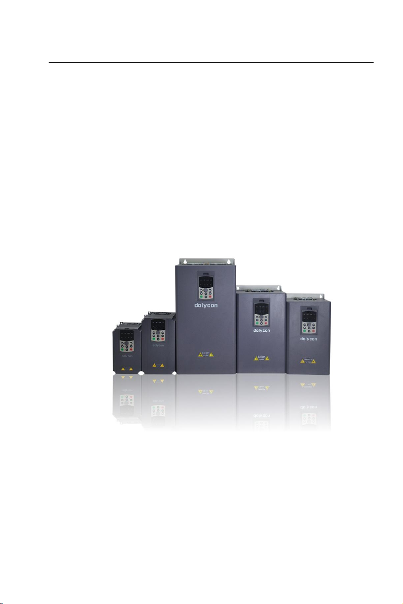
CT100 inverter Content
3.9.2 Noise control................................................................................. 45
3.9.3 Grounding......................................................................................45
3.9.4 Leakage current............................................................................45
4 Keypad operation procedure............................................................................... 47
4.1 Keypad................................................................................................................ 47
4.1.1 Unit and status LEDs............................................................................47
4.1.2 Code displaying zone........................................................................... 48
4.1.3 Buttons....................................................................................................48
4.2 Operation procedure......................................................................................... 50
4.2.1 Parameter setting..................................................................................50
4.2.2 Fault reset.............................................................................................. 50
4.2.3 Motor parameter self-identification.....................................................51
4.2.4 Password setting...................................................................................51
4.3 Display the parameters.....................................................................................52
4.3.1 Running state.........................................................................................52
4.3.2 Standby state.........................................................................................52
4.3.3 Fault state...............................................................................................52
4.4 Displayed words of code displaying zone......................................................52
4.5 Power on at the first time..................................................................................53
5 Function parameters.............................................................................................. 55
6 Detailed instructions of function parameters..................................................87
6.1 Basic function (F00 group)............................................................................... 87
6.2 Motor parameters (F01 group)........................................................................ 92
6.3 Start and stop control (F02 group)..................................................................94
6.4 V/F control (F03 group).....................................................................................98
6.5 Vector control (F04 group)............................................................................. 101
6.6 HMI interface (F05 group)..............................................................................104
6.7 Input terminals (F06 group)........................................................................... 108
6.8 Output terminals (F07 group)........................................................................ 116
6.9 Fault and protection (F08 group).................................................................. 120
6.10 PID control (F09 group)................................................................................125
6.11 Wobble, step length and count value (F10 group)...................................128
6.12 Multi-step speed and PLC (F11 group)..................................................... 131
6.13 485 communication (F12 group).................................................................136
6.14 Auxiliary functions (F13 group)................................................................... 138
6.15 Reserved functions (F14 group)................................................................. 142
6.16 Factory parameters (F15 group).................................................................142
7 Faults and solutions.............................................................................................143
7.1 Common faults and solutions........................................................................ 143
7.1.1 No display after power on..................................................................143
7.1.2 Automatic power off after power on:................................................ 143
7.1.3 The motor does not rotate after the inverter is running................ 143
7.2 Fault information and solutions..................................................................... 144
8 Daily maintenance.................................................................................................148