Dometic KRA Series Instruction manual

COPYRIGHT © 2006-2018 Dometic Corporation. All Rights Reserved.
No part of this publication may be reproduced, translated, stored in a retrieval system, or transmitted in any form or by any means
electronic, mechanical, photocopying, recording or otherwise without prior written consent by Dometic Corporation. Every precaution
has been taken in the preparation of this manual to ensure its accuracy. However, Dometic assumes no responsibility for errors and
omission. Neither is any liability assumed for damages resulting from the use of this product and information contained herein.
KRA Refrigeration Systems
(with R-404A refrigerant)
Installation, Operation & Maintenance Manual
KRA 433X
Air-and-Water-Cooled
KRA 450X
Air-and-Water-Cooled
Dometic Marine
Rev. 20180906
L-3571 English
P/N: 340161
KRA 433X
Water-Cooled-Only

L-3571 ENGLISH
Table of Contents
SAFETY INSTRUCTIONS . . . . . . . . . . . . . . . . . . . . . . . . . . 3
READ THIS MANUAL BEFORE PROCEEDING . . . . . . . . . . . 3
RECOGNIZE SAFETY SYMBOLS, WORDS AND LABELS . . . . 3
SAFETY GUIDELINES . . . . . . . . . . . . . . . . . . . . . . . . . . . . 3
SAFE HANDLING OF REFRIGERANTS . . . . . . . . . . . . . . . . . 3
DRAWINGS AND DIAGRAMS . . . . . . . . . . . . . . . . . . . . . . . 4
REFRIGERATION BASICS . . . . . . . . . . . . . . . . . . . . . . . . . 4
SYSTEM COMPONENTS . . . . . . . . . . . . . . . . . . . . . . . . . . 4
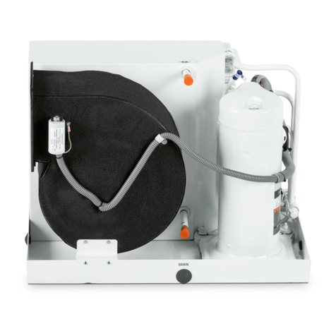
CONDENSING UNIT . . . . . . . . . . . . . . . . . . . . . . . . . . . . . 5
EVAPORATOR . . . . . . . . . . . . . . . . . . . . . . . . . . . . . . . . . 5
SUCTION LINE . . . . . . . . . . . . . . . . . . . . . . . . . . . . . . . . . 5
LIQUID LINE . . . . . . . . . . . . . . . . . . . . . . . . . . . . . . . . . . 5
REFRIGERANT METERING DEVICE . . . . . . . . . . . . . . . . . . 5
THERMOSTAT . . . . . . . . . . . . . . . . . . . . . . . . . . . . . . . . . 5
SEAWATER SYSTEM . . . . . . . . . . . . . . . . . . . . . . . . . . . . 6
REFRIGERATOR/FREEZER BOXES . . . . . . . . . . . . . . . . . . 6
SYSTEM INSTALLATION . . . . . . . . . . . . . . . . . . . . . . . . . . 6
UNPACKING AND INSPECTION . . . . . . . . . . . . . . . . . . . . . 6
IMPORTANT SAFETY CONSIDERATIONS . . . . . . . . . . . . . . . 6
Electrical Shock Hazard . . . . . . . . . . . . . . . . . . . . . 6
TOOLS REQUIRED . . . . . . . . . . . . . . . . . . . . . . . . . . . . . . 6
INSTALLING THE REFRIGERATION SYSTEM . . . . . . . . . . . . 7
Condensing Unit . . . . . . . . . . . . . . . . . . . . . . . . . . 7
Evaporator . . . . . . . . . . . . . . . . . . . . . . . . . . . . . . . 8
TXV Placement . . . . . . . . . . . . . . . . . . . . . . . . . . . 8
Quick-Connect Fittings . . . . . . . . . . . . . . . . . . . . . 8
Sight Glass/Moisture Indicator . . . . . . . . . . . . . . . . 9
Thermostat . . . . . . . . . . . . . . . . . . . . . . . . . . . . . . . 9
Refrigerant Charge . . . . . . . . . . . . . . . . . . . . . . . . 9
REFRIGERATION SYSTEM OPERATION . . . . . . . . . . . . . 9
KRA REFRIGERATION START-UPCHECK LIST . . . . . . . . . 9
Before You Start The System . . . . . . . . . . . . . . . . 9
Starting The System . . . . . . . . . . . . . . . . . . . . . . 10
System With 2 or 3 Evaporators
and 1 Condensing Unit . . . . . . . . . . . . . . . . . . . . 10
THERMOSTAT OPERATION . . . . . . . . . . . . . . . . . . . . . . . 10
Operating the Dometic Control . . . . . . . . . . . . . . 10
Parameter Programming . . . . . . . . . . . . . . . . . . . 11
Modbus Addresses for Dometic STIIC Interface . 12
SERVICING YOUR REFRIGERATION SYSTEM . . . . . . . 12
REFRIGERANT . . . . . . . . . . . . . . . . . . . . . . . . . . . . . . . 12
QUICK-CONNECT FITTINGS . . . . . . . . . . . . . . . . . . . . . . 12
RECHARGING THE SYSTEM . . . . . . . . . . . . . . . . . . . . . . 12
System Shutdown . . . . . . . . . . . . . . . . . . . . . . . . 12
Evacuate Refrigerant . . . . . . . . . . . . . . . . . . . . . 12
Charging the System . . . . . . . . . . . . . . . . . . . . . 12
ADJUSTING THE TXV . . . . . . . . . . . . . . . . . . . . . . . . . . 13
TXV METERING DEVICE . . . . . . . . . . . . . . . . . . . . . . . . 13
SIGHT GLASS . . . . . . . . . . . . . . . . . . . . . . . . . . . . . . . . 13
USER MAINTENANCE . . . . . . . . . . . . . . . . . . . . . . . . . . . 13
SEAWATER SYSTEM . . . . . . . . . . . . . . . . . . . . . . . . . . . 13
DEFROSTING . . . . . . . . . . . . . . . . . . . . . . . . . . . . . . . . 13
WINTERIZING THE SYSTEM . . . . . . . . . . . . . . . . . . . . . . 13
TROUBLESHOOTING GUIDE . . . . . . . . . . . . . . . . . . . . . 14
FIGURES & WIRING DIAGRAMS . . . . . . . . . . . . . . . . . . 16
KRA CABINET-TYPE CONDENSING UNITS . . . . . . . . . . . 16
VARIOUS FLAT-PLATE EVAPORATORS . . . . . . . . . . . . . . 16
WRAPPED-BOX EVAPORATOR . . . . . . . . . . . . . . . . . . . . 16
FLAT-PLATE EVAPORATOR DESIGNS . . . . . . . . . . . . . . . 16
DIGITAL THERMOSTAT (DOMETIC CONTROL) . . . . . . . . . 16
SINGLE-PLATE SYSTEM . . . . . . . . . . . . . . . . . . . . . . . . 17
DUAL-PLATE SYSTEM WITH JUMPER . . . . . . . . . . . . . . . 18
INSTALLATION DIAGRAM - 2 FISH BOXES WITH KRA 433X .
19
INSTALLATION DIAGRAM - 3 FISH BOXES WITH KRA 450X .
20
REFRIGERANT PRESSURE-TEMPERATURE CHART . . . . . 21
WIRING DIAGRAM FOR KRA 433X UNIT WITH 1 BOX . . . 22
WIRING DIAGRAM FOR KRA 433X UNIT WITH 2 BOXES . 23
WIRING DIAGRAM FOR KRA 450X UNIT WITH 1 BOX . . . 24
WIRING DIAGRAM FOR KRA 450X UNIT WITH 3 BOXES . 25

KRA Refrigeration System Installation, Operation & Maintenance Manual
L-3571 ENGLISH 3
SAFETY INSTRUCTIONS
READ THIS MANUAL BEFORE PROCEEDING
This manual contains essential information to ensure proper installation, operation and maintenance of your KRA refrigeration
system. Improper installation or misunderstood operating procedures can result in unsatisfactory performance and/or premature
failure of these units, so please read this manual completely before proceeding.
It is very important that you read and understand the contents of this manual before using the equipment, and it should be kept
on the boat for future reference. If you have questions or require assistance with your KRA refrigeration system, call your
authorized dealer or the Dometic Marine Service Department at +1 954-973-2477.
RECOGNIZE SAFETY SYMBOLS, WORDS AND LABELS
The following symbols and labels are used throughout this manual to indicate immediate or potential safety hazards. it is the
owner’s and installer’s responsibility to read and comply with all safety information and instructions accompanying these
symbols. Failure to heed safety information increases the risk of personal injury, property damage, and/or product damage.
SAFETY GUIDELINES
1. Allow only qualified, experienced technicians to install or service this system.
2. Install the system in accordance with all local codes. If no local codes exist, follow National Codes (NEC in the U.S.,
CEC in Canada).
3. Open the electrical disconnect switch(es) before electrically connecting the unit.
4. Before operating the unit, be certain it is properly grounded.
5. The units contain refrigerant gas under pressure. Avoid puncturing or breaking any tubing.
6. Before operating the system, complete the refrigerant connections.
SAFE HANDLING OF REFRIGERANTS
Your refrigeration system uses the refrigerant gas R-404A. Federal law forbids the intentional release of the refrigerant gas to
the environment. You should make certain that any field service is performed by a specialist with the proper equipment to
prevent any loss of R-404A during servicing.
The following warnings can not cover every conceivable situation, but they should serve as a useful guide.
WARNING
The word “WARNING” indicates hazards or unsafe practices which COULD result in severe personal injury or death.
CAUTION
The word “CAUTION” indicates hazards or unsafe practices which COULD result in minor or moderate personal injury,
product damage, or property damage.
WARNING
To avoid personal injury, shock, or death, ensure the electrical disconnect switch(es) is (are) in the OFF position
before installing, modifying, or servicing the unit. Lock out and tag the switch with a suitable warning label. Wiring
must conform with NEC or CEC and all local codes.
NOTICE
Contains R-404A fluorinated greenhouse gas in sealed equipment. Refer to the condensing unit's product data plate
label for quantity of refrigerant shown in weight, global warming potential (GWP), and equivalent tonnes of CO2
(tCO2e). Any refrigerant added should be noted on unit label.

4L-3571 ENGLISH
DRAWINGS AND DIAGRAMS
Some equipment may be shipped with specific installation sheets or wiring diagrams that may supersede the information
located in this manual.
REFRIGERATION BASICS
The instructions in this manual apply to all R-404A KRA refrigeration units. Any variations are noted in the text.
Slanted-top KRA condensing units are combination air-and-water-cooled, and the flat-top KRA condensing unit is water-cooled
only. The evaporator section of the refrigeration system may consist of stainless steel plates installed in an insulated box, or
may be copper tubing wrapped around the box, and then insulated.
The system works by removing heat from the refrigerator/freezer compartment (box) and transferring that heat to the outside air
or seawater (depending on the condenser). Removing heat from the box reduces its temperature. However, whenever the
compartment’s door is opened, more heat is introduced into the box from the warmer outside air thus increasing the box
temperature. This added heat must be removed. Heat is also transferred through the walls of the box; proper insulation will
reduce this heat transfer and keep the box cooler for longer periods of time.
The refrigerant used is R-404A. It is EPA approved, but is illegal to vent to the atmosphere. See previous notice.
SYSTEM COMPONENTS
The system consists of two main parts; the condensing unit, and the evaporator section (refrigerator/freezer box). They are
connected by copper lines or flexible hoses. Other parts include the refrigerant expansion valve (externally equalized expansion
valve), thermostat, and seawater system for water-cooled titanium condensers.
WARNING
To avoid possible explosion, death, or injury, practice safe handling of refrigerants.
WARNING
Refrigerants are heavier than air. They can “push out” the oxygen in your lungs or in any enclosed space. To avoid
possible death or difficulty breathing:
• Never sniff a refrigerant.
• Never purge refrigerant into an enclosed room or space. All refrigerants must, BY LAW, be reclaimed.
• If an indoor leak is suspected, thoroughly ventilate the area before beginning work.
• Liquid refrigerant can be very cold. To avoid possible frostbite or blindness, avoid contact and wear gloves and
goggles. If liquid refrigerant does contact your skin or eyes, get medical help immediately.
• Never burn refrigerant, as poisonous gas will be produced.
• Always follow EPA regulations.
WARNING
To avoid possible explosion:
• Never apply flame or steam to a refrigerant cylinder. If you must heat a cylinder for faster charging, partially immerse it
in warm water.
• Never fill a cylinder more than 80% full of liquid refrigerant.
• Never add anything other than R-404A to an R-404A cylinder. Service equipment used must be listed or certified for
R-404A.
• Store cylinders in a cool, dry place. Never use a cylinder as a platform or a roller.
WARNING
To avoid possible explosion, use only returnable (not disposable) service cylinders when removing refrigerant from a
system.
• Ensure the cylinder is free of damage which could lead to a leak or explosion.
• Ensure the hydrostatic test date does not exceed 5 years.
• Ensure the pressure rating meets or exceeds standard specification of DOT-4BA400.
• When in doubt, do not use the cylinder.

KRA Refrigeration System Installation, Operation & Maintenance Manual
L-3571 ENGLISH 5
CONDENSING UNIT
All units have an R-404A compressor, air-and-water-cooled or water-cooled only titanium condenser, a receiver/dryer, and a
sight glass.
The KRA condensing unit comes in an enclosed, painted aluminum box. It is available with a 1/3 HP or 1/2 HP compressor.
There are no service valves. The unit includes low-loss quick-connect couplings, a moisture indicating sight glass, a receiver
and filter/dryer and a sufficient charge of R-404A for almost all applications. Condenser cooling is either air-and-water-cooled
(slanted-top models) or water-cooled only (flat-top model).
• Air cooling is beneficial because the unit can operate even with the boat out of water. However, the unit suffers a
drop in performance in ambient temperatures above 100°F/38°C where the unit is located, and the compressor
may be damaged.
• Water-cooled units are not affected by ambient temperature and do not need ventilation. Water flow should be a
minimum of 1.5 GPM for the KRA 433X, and 2.0 GPM for the KRA 450X.
• The combination air-and-water-cooled units provide the best of both applications.
EVAPORATOR
The evaporator will be either stainless steel plate(s), or a wrapped box in which the evaporative tubing is located against the
outside surface of the box. See Figure 2: Various Flat-Plate Evaporators, page 16 and Figure 3: Wrapped-Box Evaporator,
page 16.
Stainless plates should be designed to cover about 30% to 40% of the box’s interior surface area for good freezer performance.
For instance, a box that is 36" long, 16" deep and 20" wide (92 cm x 41 cm x 51 cm), should use plates that are about 36" x 16"
(92 cm x 41 cm). This calculates to about 35% of the box’s interior surface area. Less plate area is needed for a box that is to be
only a refrigerator.
Box design is extremely important and requires considerations that are mostly outside the scope of this manual. For the power
boat industry, where constant power is available, evaporators must have a minimum of 2" (5 cm) of insulation (R7 per inch) for a
freezer. When power availability is not constant, 4" (10 cm) of R7 insulation is required. It is best to use as much insulation as is
practical. Call the Dometic Applications Department for advice on larger sized boxes, or if you are unsure.
SUCTION LINE
The suction line returns refrigerant gas from the evaporator to the condenser and should be fully insulated.
LIQUID LINE
The liquid line is the bare, 1/4" (7 mm) copper line. You must install the filter dryer assembly (packaged with the unit) at the KRA
unit on the liquid line female quick-connect fitting or the warranty will be voided.
REFRIGERANT METERING DEVICE
Refrigerant metering is handled by a thermostatic expansion valve (TXV) that is externally equalized. This is used to
compensate for varying installations. The TXV regulates the refrigerant flow into the evaporator depending on load. The valve is
either set at the factory or at installation, and does not require further adjusting. A valve which has been severely misadjusted
can damage the condensing unit, and will void warranty.
The metering valve must be insulated airtight! The TXV has a sensing bulb that must be firmly attached and thoroughly
insulated to the suction line leaving the box. Bulb placement is important. Place at 3:00 to 9:00 o’clock on the side of the suction
line.
The TXV controls the flow rate of liquid refrigerant entering the evaporator in response to the superheat of the refrigerant gas
leaving the evaporator. It keeps the entire evaporator active, without permitting unevaporated refrigerant liquid to be returned
through the suction line to the compressor. The function on the TXV is to feed liquid into the evaporator coils at a rate that will
keep liquid evaporating in all the coils, and to control that feed so that only vapor will reach the outlet (return line to the
compressor).
THERMOSTAT
A thermostat controls the operation of the condensing unit, based on box temperature. An easy-to-use digital Dometic
thermostat control is required for the installation, and digital input must be enabled (see “Parameter Programming” on page 11).
No controls other than the Dometic digital control should be used; other controls are not supported.
WARNING
Do not drill through the inside of a wrapped box evaporator. If the refrigerant tubing is punctured by doing so, it will
not be covered under warranty.

6L-3571 ENGLISH
SEAWATER SYSTEM
Condensing units that are using the water-cooled option must be installed with the necessary seawater system. The seawater
system consists of a through-hull fitting, seacock, strainer, seawater pump, seawater hose and overboard discharge. If more
than one condensing unit is supplied by a single pump, or the air conditioning system pump is being shared for the refrigeration,
a pump relay is required.
REFRIGERATOR/FREEZER BOXES
The Dometic Applications Department can assist in box design. Box design is very important to the proper operation of a
system. A poorly designed and/or built refrigerator/freezer box will result in poor operation of the overall system. Care must be
taken to address type of insulation, thickness of insulation, air circulation and drains.
Insulation thickness is important to the performance of the system. More insulation offers better performance. If the box has a
drain, a drain plug must be used. In addition, a gasket sealing the box lid is important to prevent moisture and heat-gain from
entering the box.
SYSTEM INSTALLATION
This section covers installation procedures for your refrigeration system. Please read the manual completely before attempting
to install any equipment.
This system is designed for certain capabilities and to operate under certain conditions. Any change in design conditions may
result in lower capacities. Installer must understand: a) design requirements for the system; and b) conditions under which
operation is expected and for which the system was designed. See “Tools Required” on page 6 for tools and accessories
needed for the installation.
UNPACKING AND INSPECTION
Units are securely packed in shipping containers approved by the International Safe Transit Association.
Upon arrival, carefully check all items against the packing list to ensure all cartons were received. Move units to the normal “up”
orientation as indicated by the arrows on each carton.
Check the cartons for external damage, removing the units from the cartons if necessary. If damage is found, file a request in
writing for inspection by the carrier agent immediately. The carrier is responsible for making prompt inspection of damage and
for a thorough investigation of each claim. The distributor or manufacturer will not accept claims from dealers for transportation
damage. If no damage is found, carefully remove all shipping material and properly dispose of it.
After unpacking, keep the units upright. Laying a unit on its side or top could cause equipment damage.
IMPORTANT SAFETY CONSIDERATIONS
ELECTRICAL SHOCK HAZARD
TOOLS REQUIRED
Before starting, make sure you have all of the following tools:
WARNING
Electrical shock hazard. Disconnect voltage at main panel or power source before opening any cover. Failure to
comply may result in injury or death.
To minimize the hazard of electrical shock and personal injury, this component must be effectively grounded. Refer to
the installation guidelines for further information.
• Standard tool box • Drill/hole saw
• Flaring tool (if flares are required) • Jig saw
• Refrigerant gauge manifold (rated for R-404A only) • Insulated tape
• Refrigerant tank (rated for R-404A only) • Duct tape
• Nitrogen tank • Electrical tape
• Vacuum pump • Threaded-seal tape
• Scale • Bedding compound to seal thru-hull fittings
• Micron gauge • Hardware to secure unit, pump, strainer, grilles, and
• Electronic leak detector (rated for R-404A) control panel

KRA Refrigeration System Installation, Operation & Maintenance Manual
L-3571 ENGLISH 7
INSTALLING THE REFRIGERATION SYSTEM
CONDENSING UNIT
Locate unit in a dry area where a constant source of circulated air is always available. Maximum air temperature for the system
to operate at full capacity is: 100°F/38°C measured at the condensing unit. Temperatures above this will result in reduced
capacity of the air condensing system and may cause compressor damage. Maximum water temperature for full capacity is
90°F/32°C. Air and water temperatures higher than those listed above will reduce system performance, capacity and ability to
maintain box temperature.
Any time a condensing unit is installed in an engine room, water must be provided to the unit by way of a single-station pump, or
a multi-station pump and a pump relay. The refrigeration condensing unit must have its own pump trigger. Any time a
condensing unit is installed in an enclosed space (i.e. a space that does not have airflow in and out equal to the airflow through
the condenser coil or a space that is less than 256 cu. ft./7.25 cu. m. per compressor horsepower), then the customer must
provide fresh air or water flow. Provide minimum water flow as shown in the table below for your particular unit.
If there are multiple units in a space, then add the minimum free area to get the minimum free area total for all of the units. This
also applies to the space airflow. For example, if a KRA 433X and a KRA 450X unit are in an enclosed space, the area and
airflow calculations are:
Table 1: KRA Condensing Unit Power Requirements, Dimensions, Weight
KRA
Model
Horse
Power
Voltage /
Frequency
Max Run
Amps
Height
in / cm
Width
in / cm
Depth
in /cm
Weight
lb / kg
KRA 433X 1161 1/3 115 / 60 6.3 17.77 / 45.1 8.94 / 22.7 14.5 / 37 58 / 26.3
KRA 433X 2361 1/3 230 / 60 2.38 17.77 / 45.1 8.94 / 22.7 14.5 / 37 57 / 25.8
KRA 433X 2251 1/3 220 / 50 2.4 17.77 / 45.1 8.94 / 22.7 14.5 / 37 59.8 / 27
KRA 433X 1161
Water-Cooled-Only
1/3 115 / 60 6.3 11.06 / 28.1 8.94 / 22.7 14.5 / 37 53 / 26.3
KRA 433X 2361
Water-Cooled-Only
1/3 230 / 60 2.38 11.06 / 28.1 8.94 / 22.7 14.5 / 37 52 / 25.8
KRA 433X 2251
Water-Cooled-Only
1/3 220 / 50 2.4 11.06 / 28.1 8.94 / 22.7 14.5 / 37 54.8 / 27
KRA 450X 1161 1/2 115 / 60 6 20.43 / 51.9 10.42 / 265 16.25 / 41.3 89 / 40.4
KRA 450X 2361 1/2 230 / 60 3 20.43 / 51.9 10.42 / 265 16.25 / 41.3 86 / 39
KRA 450X 2251 1/2 220 / 50 3.1 20.43 / 51.9 10.42 / 265 16.25 / 41.3 89 / 40.4
Table 2: Air-Flow and Water-Flow Requirements for KRA 4-Series Condensing Units
KRA
Model
Minimum Free Area
Cu. Feet / Cu. Meter
Air Flow
CFM / CMM
Minimum Water Flow
GPH / LPH
KRA 433X 96 / 2.72 200 / 5.66 90 / 340.69
KRA 433X
Water-Cooled-Only
96 / 2.72 Not applicable 90 / 340.69
KRA 450X 128 / 3.62 250 / 7.08 120 / 454.25
Area
96 Cu. Ft. + 128 Cu. Ft. = 184 Cu. Ft.
(2.72 Cu. M + 3.62 Cu. M = 6.34 Cu. M)
Airflow
200 CFM + 250 CFM = 450 CFM
(5.66 CMM + 7.08 CMM = 12.74 CMM)

8L-3571 ENGLISH
EVAPORATOR
• Flat Plates - Stainless-steel evaporator plates are an excellent choice for use in a bait-freezing, fish-keeping
application. Plates with backs may be mounted directly to the wall, or mounted with stand-offs so that there is an air
space behind the plate. Care must be taken to route the connecting tubes carefully to an accessible location outside
the box. When installing, consider the necessity of cleaning the box. Seal the tubing exit holes to prevent ambient air
intrusion. See Figure 2: Various Flat-Plate Evaporators, page 16.
•Wrapped Box - This type of box has a clean interior because the evaporator is wrapped around the outside of the box
walls. The box must be installed in such a way that it can be serviced or replaced without causing damage to it or to its
associated refrigeration lines or other components. Dometic cannot be held liable for any damages caused by moving
the box. Service should be done by trained professional technicians only. Refer to the Owner’s Limited Warranty Policy
document for a full explanation of what is and what is not covered under warranty.
Do not drill a hole in this box unless certain of the location of the tubing and that the tubing can be avoided. It is easy to
drill a hole in the tubing resulting in loss of refrigerant and the voiding of the warranty. In order to detect location of
refrigerant tubing, turn system on and watch for frost lines. Frost lines will appear where there is tubing.
•Insulation - Insulate all boxes with a minimum of 2" (5 cm) of R7 insulation. Use 4" (10 cm) of R7 on vessels where
power is not constantly available. Insulation thickness is important to the performance of the system, and more
insulation offers better performance.
TXV PLACEMENT
Typically, the Thermostatic Expansion Valve (TXV) bulb assembly is pre-made by Dometic, as shown in “Single-Plate System”
on page 17. The TXV must be installed in an accessible location and fastened properly. Recommended location of the TXV is
as close to the wrapped box or the plate as possible. The TXV sensing bulb is to be properly located and secured on the outlet
(suction line) of the last plate in series as close to the plate as possible. Recommended location is on a horizontal portion of
tubing on (between 3:00 and 9:00 o’clock position). The full length of the bulb should be in good thermal contact with the
refrigerant tubing. Attach it to the closest straight piece of tubing exiting the last box. If either the expansion valve or its sensing
bulb is located outside of the box, each part must be properly insulated to protect against condensation, as well as to allow
accurate temperature sensing of the bulb. The bulb must be secured to the pipe with a metal clamp to ensure firm contact with
the pipe and prevent movement. Plastic ties are not acceptable. Refer to “Adjusting the TXV” on page 13.
On systems with two plates, the TXV is connected to the inlet side of the first plate, and a jumper line is attached between the
plates. The suction line then returns to the condensing unit.
QUICK-CONNECT FITTINGS
All plates and lines have quick-connect fittings. Quick-connect (QC) fittings allow for the connection and disconnection of
refrigerant lines with minimal loss of refrigerant. They also allow for the unit to come factory charged with refrigerant. All
connections are polarized so that mis-connecting the lines, condensing unit, or evaporator is avoided. If installed correctly, they
will not leak. The majority of problems with these have been leaks due to not tightening the connections properly. Over-
tightening can damage the fitting. QCs are a one-piece model and may be tightened securely at the union nut.
Procedure for connecting the QC fittings:
1. Lightly lubricate the gasket seal and threads on the male threaded coupling with refrigeration-grade oil.
2. Thread the union nut of the female coupling onto the male threaded coupling by rotating the union nut clockwise.
3. Start the connection by hand, and then tighten the female thread connection with a 15/16" wrench while holding the
opposite coupling with a 7/8" wrench (must use two wrenches to avoid damage). This should be tightened to 10-12 ft-
lbs with a torque wrench.
4. ALTERNATE PROCEDURE WITHOUT A TORQUE WRENCH: Tighten clockwise the female coupling nut until the
coupling halves “bottom out” or a definite resistance is felt. This will require about 6 full turns. Using a marker or ink
pen, mark a line lengthwise from the female coupling hex to the male hex. Then tighten an additional 1/4 to 3/8 turn.
The misalignment of the ink line will show the degree of tightening. This final turn is necessary to ensure that the knife-
edge metal seal bites into the brass seat of the coupling halves, forming the leak-proof joint.
NOTE
Some custom applications use flare fittings on line sets in conjunction with QC fittings.

KRA Refrigeration System Installation, Operation & Maintenance Manual
L-3571 ENGLISH 9
SIGHT GLASS/MOISTURE INDICATOR
On the condensing units, there is a sight glass located directly inside the front cover. This glass will communicate many things
about the system’s operating condition.
1. The glass should show foam upon start-up. This should clear after a few minutes of running. If it doesn’t clear, the
charge could be low. If there was no foam upon start-up, the system may contain no refrigerant. The glass does not
have to be full to operate correctly. The sight glass is not to be used for charging purposes, but may help indicate an
issue with the charge. Use proper procedures as shown in “Recharging The System” on page 12.
2. There is a colored media around the hole inside the glass. When it is green, the system is dry. When it is yellow, the
system is wet. Wet systems are systems that contain moisture. This will not allow your system to work correctly. See
“TROUBLESHOOTING GUIDE” on page 14.
3. Upon unboxing the condensing unit, the sight glass may be yellow. This generally occurs because the media needs a
liquid flow over it to correctly measure the moisture content. Hook up the unit, and let it run for about 30 minutes. The
sight glass should turn green.
THERMOSTAT
The thermostat controls the operation of the condensing unit based on box temperature. Set it to a point that conforms to the
box and system design. One thermostat is required for each box. Thermostats may be located on the condensing unit, or
remotely.
Each box thermostat should be set to the designed-condition temperature. For example, a 40°F/4.4°C drink box should be set to
40°F/4.4°C for operation. Setting this thermostat down to 15°F/-9.4°C will (A) not reach this temperature as the refrigeration
system is not designed for this load, and (B) forcing any refrigeration system well below design conditions will extend the
compressor’s run time significantly, resulting in shortened unit life. To set the thermostat, see “Thermostat Operation” on
page 10.
Thermostat bulb or thermistor should be mounted one-third of the way down from the top on the longest side wall in the box.
Mount it in a position where it can sense average box temperature. Do not mount bulb or thermistor near the box opening.
Replacement thermistor cover plates are available from your dealer.
REFRIGERANT CHARGE
•All Systems - The system is relatively charge insensitive due to the large receiver that allows the condensing unit to
be charged with enough refrigerant to handle most normal plate and line configuration. No further charging should be
required for most applications.
•Linesets and Plates - Typically, these have been evacuated and vapor charged.
•Repair - If the charge is lost, or is suspected to be incorrect, the system must be evacuated and recharged with the
proper amount of R-404A. See “Recharging The System” on page 12.
See Figure 10: Refrigerant Pressure-Temperature Chart, page 21.
REFRIGERATION SYSTEM OPERATION
This section of the manual refers to essential safe operation for all KRA refrigeration systems. For any operational problems call
your authorized dealer or the Dometic Marine Service Department at +1 954-973-2477.
KRA REFRIGERATION START-UPCHECK LIST
BEFORE YOU START THE SYSTEM
1. Check that all refrigerant connections are tightened to10-12 ft. lbs.
2. Check to make sure that all refrigerant lines are secured so they do not rub against other objects during operation.
3. Ensure all suction line connections and the TXV assembly are insulated to prevent ice build-up.
4. Confirm that electrical connections are correct, and are tight.
5. Make sure that thermostat is securely mounted, and wires are routed safely.
6. Make sure that unit is securely mounted.
7. If applicable, check to make sure that airflow into and out of the unit is not obstructed.
8. Check water connections (if used) to make sure that they have correct flow direction, and that connections are tight
and have two clamps.

10 L-3571 ENGLISH
9. Confirm that thermostat sensing bulb is mounted in the correct area of the box, and that it is secure.
10. Make sure that the thermostatic expansion valve bulb is mounted correctly and securely and insulated.
11. Make sure that frequently accessed parts are easily accessible, i.e. TXV, thermostat, quick connects,
condensing unit.
12. Check the seals on the box lid to make sure that they have good contact to the box top.
STARTING THE SYSTEM
1. Turn on the designated circuit breaker on the boat’s electrical panel.
2. For units with a water-cooled condenser, first open the seacock. If pump is shared with another system, ensure that
pump circuit breaker is on.
3. Set thermostat to desired temperature.
4. Watch the sight glass to make sure that refrigerant is flowing.
5. Confirm that water (if used) is flowing out of overboard discharge (see note below).
6. Confirm that condenser fan is running (if applicable).
7. Approximately 5-10 minutes after startup, open the box top to visually confirm frost is forming on wall of box or plate.
8. After 30 minutes of run time, check the sight glass to make sure the element inside is green (no moisture
contamination).
9. Watch for a temperature decrease at the corresponding box thermostat.
SYSTEM WITH 2 OR 3 EVAPORATORS
AND 1 CONDENSING UNIT
1. Check all wiring to confirm that each thermostat brings on the corresponding box and the condensing unit and pump
(optional).
2. To check pressures and refrigerant charge, if necessary, follow these instructions:
• Turn on only one box. Make sure that box works correctly. Wait approximately 10 minutes.
• Turn off the first box, turn on the other one. Wait approximately 10 minutes.
• Turn all boxes on, and check for frost on box/plate surfaces. If not fully frosted, check subcool.
3. Follow procedures for “Starting The System” on page 10.
THERMOSTAT OPERATION
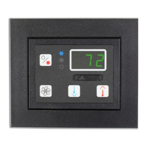
For operational reference, see Figure 5: Digital Thermostat (Dometic Control), page 16. For error codes, see Table 6:
Thermostat Display Error Messages (digital Dometic control), page 15.
OPERATING THE DOMETIC CONTROL
Powering On The System
1. When the control is powered up (breaker on), the Dometic control display will light up showing all the icons and 888.
That is followed by a display of r5.2 then - - -.
2. After - - - displays, depending on the mode it was in when it was last powered OFF, the display could flash between
OFF and the box temperature, or start the cooling process by flashing the compressor delay icon for approximately
3 minutes, then the compressor will start and cooling will begin.
3. If the KRA unit was in the OFF mode, the control display alternates between OFF and the temperature reading. To turn
on the compressor, press and hold the upper right power button for 2-3 seconds.
4. The control display will change from OFF and alternating temperature display to a constant temperature display. If the
temperature setpoint is lower than the box temperature now displayed, the compressor icon will flash indicating a
call for cooling, and there will be a 3-minute delay before starting the compressor. If compressor icon is on but not
NOTE
The seawater pump will cycle automatically whenever the compressor is running. Regularly check for seawater flow
by observing the overboard discharge when the system is first turned on. If you do not observe steady water flow, turn
off the system and check for obstructions in the seawater cooling system.

KRA Refrigeration System Installation, Operation & Maintenance Manual
L-3571 ENGLISH 11
flashing, the compressor is running. If the temperature set point is higher than the box temperature, the compressor
will NOT turn on but will indicate box temperature.
Setting Temperature
1. Press and hold the set button until SET flashes in the display followed by numbers flashing and the cold icon .
2. Use the power button for UP and the aux button for DOWN to change the temperature.
3. Press the set button to save the new setting.
PARAMETER PROGRAMMING
Procedure
1. Press Prg/Mute one or more times to make sure you are at the standard display (showing temperature of box).
2. Press and hold Prg/Mute for more than 3 seconds (if an alarm is active, the buzzer will be muted). The display will
show the code PS (for password) and the number 0.
3. Press the UP or DOWN buttons to enter the password: 22. Press the SET button. The display shows
parameter /2.
4. Press the UP or DOWN buttons to reach the desired parameter as shown in Table 3, below. While scrolling, a
code is displayed that represents the parameter.
5. When you find the parameter you want, press the SET button to display its current value. Press the UP or DOWN
buttons to change it, then press the SET button to temporarily save it and display the the parameter code again.
6. Repeat steps 4 and 5 to set other parameters, if needed.
7. TO PERMANENTLY SAVE all the parameter changes you made, press Prg/Mute for 5 seconds. This also exits the
parameter setting area and returns the control to normal operation.
Programming Parameter Codes
DO NOT CHANGE THE PROGRAMMING UNLESS ABSOLUTELY NECESSARY. There are many parameters included in the Dometic
control, but ONLY those shown in the following table should ever be changed, and changes will rarely be needed.
Table 3: Dometic Preset Control Parameter Descriptions for KRA 433X and 450X Units
CODE DESCRIPTION UNITS SET TO SPECIAL NOTES
/5 Display temperature in Fahrenheit or Celsius.
Fahrenheit (1) is default.
Temperature
scale
1 for F
0 for C
/tl Probe 1 -- 2
/tE Probe 1 -- 2
/A2 Probe 2 is not used. This must be set to 0 or system will fault. -- 0
r3 Direct cooling -- 1
rd Temperature differential Degrees 2
c0 Start delay for Power ON. Min 3 minute wait time to Minutes 3 These 3 parameters
must be set to 3
minutes or more to
avoid compressor
failure.
c1 Time between starts Minutes 3
c2 Minimum compressor OFF time Minutes 3
A4 Low-pressure switch (error shows LP) -- 8
A5 High-pressure switch (error shows 1A) -- 1
h0 Modbus device address for STIIC applications only Unique Modbus address See Table 4 below.

12 L-3571 ENGLISH
MODBUS ADDRESSES FOR DOMETIC STIIC INTERFACE
To implement remote monitoring and control of the KRA system(s) via the Dometic Smart Touch Integrated Intelligence Control
(STIIC), use the Modbus settings shown in the table below. There is a maximum of 3 controllers per KRA unit on STIIC.
SERVICING YOUR REFRIGERATION SYSTEM
REFRIGERANT
This refrigeration system uses R-404A refrigerant. With a properly designed system, R-404A will perform well for temperatures
down to 0°F/-32°C. R-404A is a blended-component refrigerant and should be charged in a liquid state. Never charge in the gas
(vapor) phase. Because R-404A is a blend of gases, the most volatile gas will boil off first, so if there is a leak, the system will
lose a portion of the blend first, creating an improper mixture and poor performance.
QUICK-CONNECT FITTINGS
QCs may be used in a similar manner as base valves. To check compressor suction valve integrity, remove the liquid line QC
from the condensing unit. In 2-3 minutes or less, the unit should be pulling a vacuum. You may also use the QCs to troubleshoot
leaks by narrowing down the search to individual parts, such as the liquid line, suction line, box, and condensing unit.
Disconnect the QCs, and pressurize all parts separately.
RECHARGING THE SYSTEM
You only need to recharge the system if it was improperly charged or after a repair, and only after checking for leaks and finding
none.
SYSTEM SHUTDOWN
It is best if the system can be turned off for 8-12 hours prior to servicing to allow the refrigerant to reach ambient temperature.
This will expedite the recovery of the refrigerant, but is not necessary.
EVACUATE REFRIGERANT
1. Connect manifold gauges to both high and low side ports. Attach center line of gauge set to recovery apparatus.
2. Recover system per governing EPA regulations.
3. With the manifold gauges still connected to service ports, attach the center line of gauge set to vacuum pump.
4. Repeat vacuum process until a vacuum of 200-400 microns is achieved. If the system has been open to the
environment, allow a minimum evacuation time of 12 hours. Close manifold valves and turn off the pump. If no vacuum
is lost, proceed with charging.
CHARGING THE SYSTEM
Refer to Figure 10: Refrigerant Pressure-Temperature Chart, page 21.
1. Remove line from vacuum pump and connect to a R-404A bottle. The charge must be weighed in.
2. Pressurize the charging lines with liquid R-404A refrigerant.
3. With system OFF, charge on high side and allow the correct amount of R-404A to flow into the system by weight
indicated on data label. Typical pressures are 20 PSI on the low side and 210 PSI on the high side (plus or minus 4
PSI) at typical entering temperatures of 73 to 75°F/23 to 24°C for air or water condenser. Since each installation is
unique, your readings may vary. If questionable, call Dometic Technical Support.
Table 4: Modbus Device Addresses for KRA Units Using STIIC
Condensing Unit Modbus Address Extra Hardware KRA Parameter Code STIIC Connection
KRA unit #1 40, 41, or 42 IROPZ48500 Dongle h0 J26-FB2
KRA unit #2 43, 44, or 45 IROPZ48500 Dongle h0 J26-FB2
KRA unit #3 46, 47, or 48 IROPZ48500 Dongle h0 J26-FB2
KRA unit #4 49, 50, or 51 IROPZ48500 Dongle h0 J26-FB2
KRA unit #5 52, 53, or 54 IROPZ48500 Dongle h0 J26-FB2
KRA unit #6 55, 56, or 57 IROPZ48500 Dongle h0 J26-FB2

KRA Refrigeration System Installation, Operation & Maintenance Manual
L-3571 ENGLISH 13
4. The best way to make sure the unit is charged properly is by the subcooling method. This will ensure that you have a
good liquid seal to the TXV with no flash gas or vapor. Typical subcooling is 6 to 10°F/-14 to -12°C depending on the
condensing temperatures. Refer to Figure 10: Refrigerant Pressure-Temperature Chart, page 21.
ADJUSTING THE TXV
On rare occasions, a qualified technician may need to make an adjustment, but these adjustments are slight. Use a wrench
to remove the nut covering the superheat adjustment valve stem. This exposes the valve stem. Once the system has had
sufficient running time to stabilize the box temperatures, adjustment should be made in 1/4-turn increments only. Use the
wrench to make adjustments. After each incremental adjustment, allow 15 to 20 minutes for the expansion valve diaphragm to
stabilize.
Looking at the stem-end of the valve:
• Turn the valve stem clockwise to close the valve; this will decrease the flow of refrigerant and increase the superheat.
• Turn the valve stem counter-clockwise to open the valve; this will increase the flow of refrigerant and decrease the
superheat.
• One full turn of the valve stem equals 4.5° of superheat.
• Follow directions with the valve. Replace the outer nut, and tighten to 3 ft-lbs. Insulate valve and bulb fully.
TXV METERING DEVICE
If service or replacement is needed, follow manufacturer’s recommendations for more information. Call Dometic Technical
Support.
SIGHT GLASS
See “Sight Glass/Moisture Indicator” on page 9“ in the “Installing the Refrigeration System” section.
USER MAINTENANCE
SEAWATER SYSTEM
Check the seawater strainer daily. Remove any debris. If you are in waters where jellyfish or other debris are a problem, you
may find it necessary to add a strainer on the outside of the through-hull fitting.
Verify that all seawater connections are tight, and check for water flow from the overboard discharge. The centrifugal seawater
pump does not need any regular maintenance.
DEFROSTING
Defrosting of your freezer box is required to keep the unit working at peak performance. Defrost the unit whenever more than
1/4" (7 mm) of ice or frost has accumulated on the plates or box sides.
To defrost, remove all the contents from the box and remove drain plug (if applicable), then disconnect the power to the KRA
unit. Leave unit off until all ice has melted. Be sure to replace drain plug once unit has finished defrosting (if applicable).
To accelerate the defrost process, remove plug and use fresh water to melt ice and rinse the box clean. Never use a mechanical
device to remove ice. Damage to box liner is not covered under Dometic Warranty.
WINTERIZING THE SYSTEM
Make sure all water has drained from the refrigerated box. On seawater-cooled units, close the seacock, and remove inlet hose
from pump and outlet hose from unit to allow all water to drain from the system. Drain and clean seawater strainer.
NOTE
Check ability of vacuum pump to achieve 200-400 microns by connecting micron gauge directly to pump. If it does not
achieve 200-400, service or replace pump.
NOTE
If moisture has been a problem, refer to Refrigeration Bulletin 02-1 for instructions on clean up. This bulletin is
available on the Marine Resource Center under Technical Field Notices: “Control of Moisture in Refrigeration
Systems” (FN#175-I2).
CAUTION
System contains R-404A refrigerant. Recovery machines containing mineral-based oils should not be used.

14 L-3571 ENGLISH
TROUBLESHOOTING GUIDE
Before you call for service, review this list of problems and solutions. It may save you time and expense. This list contains
common occurrences that are not a result of defective workmanship or materials. If you need service after trying these
procedures, call your dealer. Also reference the wiring diagrams in this manual.
Table 5: General Troubleshooting
PROBLEM POSSIBLE REASON/SOLUTION
Compressor and fan (or
pump) does not run.
1. Circuit breaker off. Turn on or reset circuit breaker.
2. Thermostat set incorrectly. Check thermostat. Set for a cooler setting.
3. High/Low pressure switch. Check the Dometic control for fault LP or 1A. Call
technician.
Fan or pump operates but
compressor does not (high
pressure switch or thermal
overload has tripped)
1. Low voltage to unit. Check for low voltage to unit. Klixon may be open.
2. Poor condenser cooling. Check fan and coil for proper airflow. Ventilate area if
temperature is above 100°F/38°C. Check seawater system.
3. High/Low pressure switch. Check the Dometic control for fault LP or 1A. Call
technician.
Compressor and fan (or
pump) running, but box does
not cool.
1. Poor condenser cooling. Check fan and coil for proper airflow. Ventilate area if
temperature is above 100°F/38°C. Check seawater system for proper flow.
2. Thermostatic Expansion Valve (TXV) not set correctly. See technician for service.
3. Low refrigerant charge. Check for a refrigerant leak and repair. Evacuate system
and recharge with the correct amount of R-404A.
4. TXV Mechanical failure. Have technician confirm diagnosis and replace.
System starts to cool, but
stops as plates freeze.
1. Moisture in system. Check sight glass for moisture. Yellow indicates moisture;
green indicates dry system.
Compressor operates, but
seawater pump doesn’t.
1. Pump relay failure. Turn on or reset pump breaker. Check pump relay and pump
relay trigger.
Unit does not run. 1. Power is OFF at panel. Turn Power ON, check to see if thermostat display comes
on.
2. Thermostat is set incorrectly or may be faulty. If the display is on, check for proper
thermostat setting. Ensure the correct voltage at thermostat.
If the thermostat is showing a fault code, refer to “Thermostat Display Error Messages
(digital Dometic control)” on page 15.
If thermostat still does not send voltage to the condensing unit or if fault code is
present, replace thermostat.
3. No voltage is getting to the thermostat, but the panel switch is on. Check for
loose or missing wiring connections behind the control, then in electrical box. Make
sure that there is not another in-line cut-off switch.
4. Start component failure. Check basic electrical components for failure. Replace if
necessary. See technician.
5. Compressor failure. See technician.
Displays not lit. 1. Power disconnected. Check circuit breaker.
2. Loose connection. Check for loose connections.
3. Wrong voltage. Check voltage input of control.
4. See technician.

KRA Refrigeration System Installation, Operation & Maintenance Manual
L-3571 ENGLISH 15
Insufficient cooling of box. 1. Excessive frost is in box. Turn unit OFF, and defrost according to instructions in
“Defrosting” on page 13.
2. Improperly set thermostat. Review “REFRIGERATION SYSTEM OPERATION” on
page 9.
3. Excessive open-box time. Unit requires time to catch up after being opened. Decide
what you are going to get before opening the box, then conduct removal quickly to
prevent warm air infiltration.
4. Recent addition of large quantities of warm items. Unit will slowly pull the heat out
of the warm items, allow for recovery time.
5. Poor seals, no drain plug. Poor seals allow ambient air to infiltrate box, bringing
moisture with it. Replace seals if necessary. Leaving the drain plug out during regular
operation allows outside air, possibly even hazardous or bilge gases, to enter box.
6. Improperly set Thermostatic Expansion Valve (TXV). Have a certified technician
check the suction pressure, and set the valve according to “Recharging The System”
on page 12.
7. Low refrigerant charge. Have a certified technician check for this problem. If the
technician finds a low charge condition, he/she should check for leaks using an
electronic leak detector.
Unit should be recharged to rated system capacity.
8. High condensing temperature. High ambient temperature – introduce cooler air
into compartment that houses the condensing unit.
High water temperature – while you cannot remedy this problem, you can help by
introducing cooler air into the compartment that houses the condensing unit.
Pump not operating – find cause and remedy.
Condenser fan failure – replace component.
9. Improperly mounted temperature sensor in refrigerated box. Refer to “SYSTEM
INSTALLATION” on page 6 for proper location of sensor. If drilling in a wrapped box,
be sure to confirm placement of evaporator lines before drilling. This can be
accomplished by turning the condensing unit on, and checking for frost lines in the
box.
10. Moisture in system. Have a certified technician check for this problem. If there is
moisture present, he/she will decide a course of action to take which should include:
leak check, installation of liquid line filter/dryer, evacuation, and recharging. Unit
should be checked at later date for any remaining moisture.
11. Inadequate design. Not every box is designed for every condition. It may be that
your box was not designed properly. If this is the problem, replacement of the box or
condensing unit may be the only solution.
Table 6: Thermostat Display Error Messages (digital Dometic control)
ERROR CODE DESCRIPTION AND CORRECTION
IA High Pressure Fault
LP Low Pressure Fault
rE and E0 (flashing) Temperature Probe Fault (a shorted or open circuit)
EE Unit parameter EEPROM error
EF Operating parameter EEPROM error
Table 5: General Troubleshooting (continued)
PROBLEM POSSIBLE REASON/SOLUTION

16 L-3571 ENGLISH
FIGURES & WIRING DIAGRAMS
Figure 1: KRA Cabinet-Type Condensing Units
Figure 2: Various Flat-Plate Evaporators
Figure 3: Wrapped-Box Evaporator
Figure 4: Flat-Plate Evaporator Designs
Figure 5: Digital Thermostat (Dometic Control)
Flat plate with flanges
FL = Flange Mount

KRA Refrigeration System Installation, Operation & Maintenance Manual
L-3571 ENGLISH 17
Figure 6: Single-Plate System
TXV
Valve
KRA
UNIT
3/8" Copper Tube
Suction Line
Insulate Completely
REV DATE APRDWGREVISION DESCRIPTION
PROPRIETARY NOTE: THE INFORMATION CONTAINED
WITHIN THIS DOCUMENT IS THE PROPERTY OF DOMETIC
CORPORATION. ANY ATTEMPT TO COPY OR DISTRIBUTE
WITHOUT WRITTEN CONSENT FROM DOMETIC
CORPORATION SHALL BE CONSIDERED UNLAWFUL AND
CAN BE CONTESTED IN A COURT OF LAW.
APR BY:
DWG BY:
SCALE:
DATE:
REV
DWG
PART NUMBER: D2570003 O.I.
KRA TYPICAL INSTALLATION
1 PLATE
2/19/18
NTS
CT
BJL
1/4"CopperTube
Typ.SSFreezerPlate

18 L-3571 ENGLISH
Figure 7: Dual-Plate System with Jumper
12.00
X
TXV
Valve
KRA
UNIT
3/8" Copper Tube
Suction Line
Insulate Completely
PJA12-SI
12 " Between Fittings. Some Models show a second
Measurement for (X) which is the Height as Shown
S for Stainless Tubing, Copper is also Available
and I for Factory Insulated
REV DATE APRDWGREVISION DESCRIPTION
PROPRIETARY NOTE: THE INFORMATION CONTAINED
WITHIN THIS DOCUMENT IS THE PROPERTY OF DOMETIC
CORPORATION. ANY ATTEMPT TO COPY OR DISTRIBUTE
WITHOUT WRITTEN CONSENT FROM DOMETIC
CORPORATION SHALL BE CONSIDERED UNLAWFUL AND
CAN BE CONTESTED IN A COURT OF LAW.
APR BY:
DWG BY:
SCALE:
DATE:
REV
DWG
PART NUMBER: D2570004 O.I.
KRA TYPICAL INSTALLATION
2 PLATES WITH JUMPERS
2/19/18
NTS
CT
BJL
PJA12-SI
Plate
Jumper
Typ. SS Freezer Plates
1/4"CopperTube

KRA Refrigeration System Installation, Operation & Maintenance Manual
L-3571 ENGLISH 19
Figure 8: Installation Diagram - 2 Fish Boxes with KRA 433X
REV DATE APRDWGREVISION DESCRIPTION DOMETIC
APR BY:
DWG BY:
SCALE:
DATE:
REV
DWG
PART NUMBER:
PROPRIETARY NOTE: THE INFORMATION CO NTAINED
WITHIN THIS DOCUMENT IS THE PROPERTY OF DOMETIC
CORPORATION. ANY ATTEMPT TO COPY OR DISTRIBUTE
WITHOUT WRITTEN CONSENT FROM DOMETIC
CORPORATION SHALLBE CONSIDERED UNLAWFUL AND
CAN BE CONTESTED IN A COURT OF LAW. D2570001 O.I.
N/A
KRA
KRA433X 2 BOX
ASSEMBLY LAYOUT
2/15/18
NTS
CT
BJL

20 L-3571 ENGLISH
Figure 9: Installation Diagram - 3 Fish Boxes with KRA 450X
REV DATE APRDWGREVISION DESCRIPTION DOMETIC
APR BY:
DWG BY:
SCALE:
DATE:
REV
DWG
PART NUMBER:
PROPRIETARY NOTE: THE INFORMATION CONTAINED
WITHIN THIS DOCUMENT IS THE PROPERTY OF DOMETIC
CORPORATION. ANY ATTEMPT TO COPY OR DISTRIBUTE
WITHOUT WRITTEN CONSENT FROM DOMETIC
CORPORATION SHALL BE CONSIDERED UNLAWFUL AND
CAN BE CONTESTED IN A COURTOF LAW. D2570002 O.I.
N/A
KRA
KRA450X 3 BOX
ASSEMBLY LAYOUT
2/15/18
NTS
CT
BJL
This manual suits for next models
8
Table of contents
Other Dometic Marine Equipment manuals

Dometic
Dometic XPA1012B User manual

Dometic
Dometic PS250 User manual

Dometic
Dometic SB39452 User manual

Dometic
Dometic Xtreme NFB SHX7606 User manual

Dometic
Dometic Optimus EPS User manual

Dometic
Dometic Passport I/O Legacy User manual

Dometic
Dometic VacuFlush VHT12 User manual

Dometic
Dometic DCU User manual
Popular Marine Equipment manuals by other brands

Harken
Harken 3299 instructions

Boss marine
Boss marine MR1520W user manual

Shoremaster
Shoremaster SLIDE OFF-DECK Instructions and Safety Tips

Garmin
Garmin Reactor 40 installation instructions

Potter
Potter PAD100-SB quick start guide

Standard Communications
Standard Communications Horizon WS45 owner's manual