Dometic Xtreme NFB SHX7606 User manual

MECHANICAL MARINE
STEERING
Mechanical Steering for Outboard Powered Vessels
Xtreme™NFB™Helm — SHX7606
Installation and User Manual
EN
[REVISION 5] Form No. 4445104072 | ©2023 Dometic

All information, illustrations and specifications in this manual are based on
the latest information available at the time of publishing. The illustrations
used in this manual are intended as representative reference views only.
Moreover, because of our continuous product improvement policy, we
may modify information, illustrations and/or specifications to explain and/
or exemplify a product, service or maintenance improvement. We reserve
the right to make any change at any time without notice.
©2023 Dometic
All Rights Reserved. This document, subject matter and all information
herein is the sole, exclusive and confidential property of Dometic and shall
not be disclosed, copied, reproduced or used in whole or in part for any
purpose other than as specifically authorized in writing by Dometic.
is a registered trademark of the American Boat &
Yacht Council (http://www.abycinc.org)
is a registered trademark of the National Marine
Manufacturers Association (http://www.nmma.org)
Xtreme and SeaStar are trademarks of Dometic.
Loctite is a trademark of Henkel Corporation.
This book contains:
• the installation instructions for the Xtreme™NFB™helm and steering
system. Helm part number SHX7606 (patents pending). Xtreme™NFB™
or No Feed Back helms have a clutch mechanism to prevent engine
torque at the steering wheel. This reduces operator fatigue by eliminating
the constant fighting of the wheel. Instructions for installing steering
cables are also included.
• In addition to this kit the following components are required for a
complete system:
– Bezel kit SBX76061 (90°)
– SSCX64xx cable (where xx is length in feet)
– Engine connection kit (refer to Dometic SeaStar catalog)
– Steering wheel (refer to Dometic SeaStar catalog; maximum wheel
diameter 16”, maximum wheel dish 5”)
About this Book
NOTICE!
Installer: these instructions contain important safety information and must
be forwarded to the boat owner.

i
EN
Table of Contents
1 Important Safety Information .............................................. 1-1
1.1 Explanation of symbols .................................................... 1-1
1.2 Safe operation............................................................... 1-2
1.3 Safety considerations for installers .................................... 1-3
2 System Installation .............................................................. 2-1
2.1 Preparation for installation .............................................. 2-1
2.2 Steering cable routing .................................................... 2-1
2.3 Helm installation ........................................................... 2-1
2.4 Steering cable installation ............................................... 2-1
2.5 Connection to engine ................................................... 2-3
2.6 Operation and maintenance notes .................................. 2-4
3 Mounting Template ............................................................. 3-1
3.1 Helm — SHX7606 ......................................................... 3-1

ii EN
Notes

1-1
EN
1 Important Safety
Information
Safe operation of the Xtreme™NFB™helm and steering system depends on
proper installation and maintenance of the system, as well as the operator’s
safe judgment, boating knowledge, and expertise.
The installer and operator must read and understand the safety requirements
in this section before installing or using the steering system. If you have any
questions about safe installation or operation of this system, contact
Dometic Marine. Please don’t guess.
The symbols below are used throughout this publication to alert you to
potential hazards involved with the operation and installation of this product.
Observe these warnings and notices carefully. The safety alerts alone
cannot eliminate hazards; strict compliance with any special instructions
during installation, operation, and maintenance, along with common sense
operation, are important measures to prevent hazardous situations.
1.1 Explanation of symbols
DANGER!
Safety instruction: Indicates a hazardous situation that, if not avoided,
will result in death or serious injury.
WARNING!
Safety instruction: Indicates a hazardous situation that, if not avoided,
could result in death or serious injury.
CAUTION!
Safety instruction: Indicates a hazardous situation that, if not avoided,
could result in minor or moderate injury.
NOTICE!
Indicates a situation that, if not avoided, can result in property damage.
NOTE
Supplementary information for operating the product.

1-2 EN
General
• Read and understand this manual and any other documentation
provided with your steering system.
• Know and obey all applicable federal, state, and municipal laws and
regulations that govern boating in your area. Dometic recommends all
boat operators take a boating safety course.
• Never operate a boat while under the influence of drugs or alcohol.
Before every use
• Verify immediate steering response when turning steering wheel.
• Check for binding, loose, worn or damaged components. If found,
repair or replace.
• Check steering cable for stiffness, cracks, or other damage. If found,
replace steering cable.
• Periodically lubricate cable output ram and engine tilt tube with a
waterproof marine grease.
During use
• Wear a Coast Guard-approved personal flotation device (PFD).
• Attach the engine shut-off lanyard to your PFD.
• Do not allow anyone not familiar with the controls (steering, shift/throttle
etc.) to operate the boat.
After use
• Rinse the Xtreme™steering system thoroughly, using only fresh, clean water.
• Do not use acetone, or cleaners containing ammonia, acids, or any other
corrosive ingredients, on any steering components.
• Some products formulated for cleaning fiberglass hulls are known to
aggressively corrode stainless steel shafts. If using a hull cleaner, avoid
overspray on the Xtreme™steering system. Rinse off any overspray
immediately with fresh, clean water.
WARNING!
Do not operate the boat if any component is not in proper working order.
It may result in a loss of steering control, which could lead to a collision
and/or ejection from the boat, causing property damage, personal injury,
and/or death.
1.2 Safe operation
WARNING!
The safety information below is intended to inform you of hazards that
may be present when operating a boat equipped with Dometic controls
and steering. Read and understand this information.

1-3
EN
Before installation
• Read this installation manual and understand any other manual(s) supplied
with the system.
• Ensure you have all the required components on hand before you start.
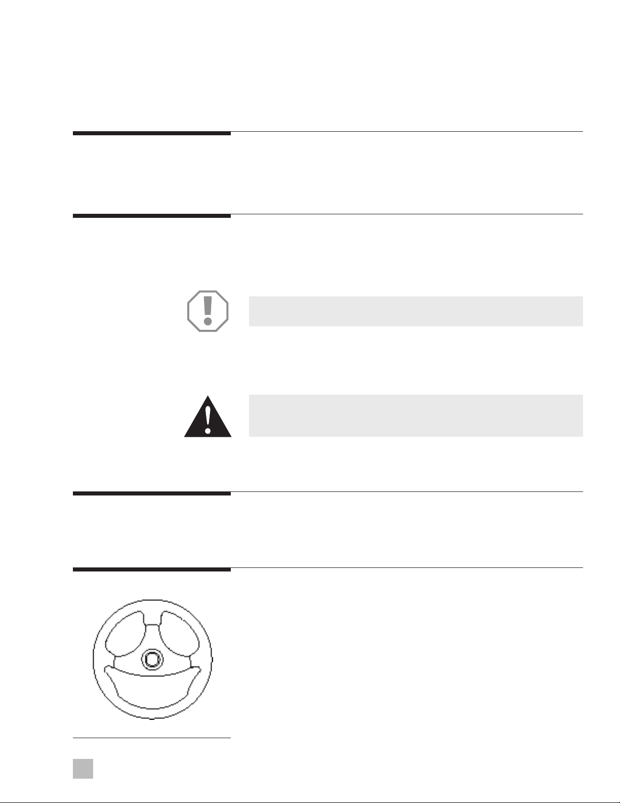
• Do not use a wheel-mounted trim switch with coiled cord. The cord can
wrap around the steering wheel shaft and inhibit steering.
During installation
•
Install components as instructed in the installation manual. Some component
parts and kits may contain additional installation instructions – refer also
to those instructions.
•
Do not substitute any component of the system without written authorization
from Dometic. Dometic parts are rigorously engineered and tested to
ensure system integrity. Substitution of components may compromise
safety, performance, and reliability.
• All steering components including the Xtreme™steering system must be
compatible with, and rated for, the engine installed on the boat.
•
To avoid excessive steering loads, and to get the best steering performance,
the outboard motor, tilt position or trim tabs must be adjusted as instructed
in the motor manufacturer’s operation manual.
• Do not attach any electric ground wires to the helm. This will result in an
electrolytic reaction to the steering system that may result in system
failure or greatly reduced service life.
• If an instruction is unclear, contradictory, or you are otherwise unsure how
to proceed, do not guess. Contact Dometic Marine technical support at
ts.mechanical@dometic.com.
After installation
• Perform the system inspection checks described in the installation manual.
• Correct any interference issues before handing the boat to the owner.
• If steering cable is stiff in operation, it is unsafe to use and must be
replaced immediately.
• Check steering cable for stiffness, cracks, or other damage. If found,
replace steering cable.
• Helms must not be disassembled for any reason.
1.3
Safety considerations for installers
WARNING!
Failure to comply with Dometic instructions may result in loss of steering
control, which could lead to a collision and/or ejection from the boat,
causing property damage, personal injury, and/or death.

1-4 EN
NOTICE!
When replacing an existing steering system it is recommended that you
stay with the style (rotary or rack) the boat manufacturer installed. Never
change your steering from a dual cable to a single cable system, as this
could cause an unsafe boating condition.
NOTICE!
Helms and cable assemblies are supplied lubricated ready for installation, do
not add any lubricant to either assembly. Use of other lubricants can cause
damage to the steering cable, resulting in the cable seizing or premature
wear. Keep the cable and drive assembly clean during installation. Dirt will
damage the system and cause premature wear. Do not take the plastic
sleeve off the end of the cable until you are ready to install it into the helm.
This notice does not include the engine output ram end of the cable.
DANGER!
If steering cable is stiff in operation, it is unsafe to use and must be
replaced immediately.
WARNING!
Before starting installation read these instructions and engine makers
instructions thoroughly. Failure to follow either of these instructions or
incorrect assembly can result in loss of control and cause property damage,
injury, or death.
WARNING!
Do not substitute parts from other manufacturers, they may cause a
safety hazard for which Dometic cannot accept responsibility.
Use only Dometic SSCX64 Xtreme™steering cable with this helm.
WARNING!
To avoid excessive steering loads, and to get the best steering performance,
the outboard motor or trim tabs and tilt position must be adjusted as
instructed in the motor manufacturers operation manual. Failure to do so
can effect the performance of the boat and its safe operation which may
cause property damage, injury, or death.
WARNING!
Do not attach any electrical ground wires to the helm. This would result
in an electrolytic reaction to the steering system that may result in system
failure or greatly reduced service life.
WARNING!
Helms must not be disassembled for any reason. Failure to reassemble
correctly may lead to total failure of the system, which could result in
property damage, injury, or death.

2-1
EN
Figure 2-1.
2 System Installation
2.1 Preparation for installation
2.4 Steering cable installation
2.3 Helm installation
2.2 Steering cable routing
NOTICE!
Do not make bends of less than 8” radius
CAUTION!
Cables must not be bundled together with electrical wiring.
Cables must not rest on sharp edges which can cause chafing.
Before the steering cable can be installed, the helm, bezel, and steering
wheel must be fully installed as shown in the bezel kit instructions.
Before the steering cable is installed the steering wheel should be positioned
as shown in figure 2-1, so that it is in the correct orientation when the
installation is completed.
Step 1
Remove the pin from the cable entry spigot of the helm. Do not remove the
tag from the pin. The back of the helm is marked for typical installation.
Step 2
Remove the protective sleeve from the cable end, making sure that no dirt
gets on the lubricated cable end. Feed the cable into the upper helm
spigot until it contacts the internal gears.
Refer to Bezel Kit (SBX76061) instructions.
The helm assembly can be mounted for either port or starboard cable
routing. Steering cables, if possible, should be routed to the starboard
side of the boat in order to balance engine torque.
When routing the steering cable, select a path with the minimum number
of bends, making the bends as large as possible.
Sharp or frequent bends will result in hard steering and premature cable
wear. When it is necessary to pass through a bulkhead, a 1-1/2” diameter
hole is required. Cable(s) should be loosely clamped or tied for support at
regular intervals.

2-2 EN
Figure 2-2.
Then turn steering wheel counter clockwise to draw the cable fully into the
helm. Continue turning the wheel after the cable end enters the helm spigot,
you will feel some pressure then hear a click. Keep turning past that point
until you can not turn any further.
That click you heard was the locking mechanism engaging with the cable end.
Turn the steering wheel fully in the opposite direction until you can not
turn any further, and check that the cable end fitting is retained inside the
entry spigot.
Step 3
Replace the pin as shown in figure 2-3, making sure that it is fully seated.
Do not remove tag from pin. This tag must be left in place for vessel safety
during future steering maintenance.
Step 4
Turn the steering wheel fully to both extremes of rotation and check that
the cable fitting is retained in the entry spigot.
Step 5
Feed spent travel tube (item 2, figure 2-2) over the exposed cable end until
you hear it click into place in the helm spigot. Then insert pin as shown in
figure 2-2 until it is fully seated.
4
4
1
2
CABLE
Item
No. Description Qty.
1
2
3*
4
Helm
Spent Travel Tube
1/4 x 3/4” Long Hex. Bolt
Pin
1
1
3
2
* Pictured in bezel kit instructions.

2-3
EN
Figure 2-3.
2.5 Connection to engine
For engine-mounted steering systems, slide the output ram through the engine
support tube. Thread the cable coupler nut fully onto the support tube.
For a boat-mounted steering system, attach the cable to the boat and engine
in accordance with the instructions furnished with the connection kit.
NOTICE!
The coupler nut has a locking ring in the threads. Make sure the nut is drawn
up fully and its internal plastic locking ring is engaged. If you do not tighten
this nut fully there will be excessive play in the steering system. Connect
the cable output ram to the engine tiller arm as shown in the instructions
packed with the connection kit.
CAUTION!
Ensure that the cable output end is not bent when installing into the
engine. If necessary remove the engine from the boat.
Step 6
Rotate the steering wheel several times from stop to stop, and watch the
movement of the steering cable output ram. On starboard routed cables,
turning the steering wheel clockwise should cause the ram to extend. On
port routed cables, turning the steering wheel clockwise should cause the
ram to retract.
CAUTION!
The output ram end of the steering cable should be lubricated with a
good quality waterproof marine grease before being inserted into the
support tube.

2-4 EN
1. Aer a few hours of operation and at frequent intervals thereaer, check
all fasteners and the complete steering system for security and integrity.
DANGER!
Loosening or loss of one or more fasteners may cause failure of the steering
system, resulting in loss of steering control and could cause property
damage, injury, or death.
DANGER!
If steering cable is stiff in operation, it is unsafe to use and must be
replaced immediately.
DANGER!
Do not cover cracks with tape or other sealants, this will create a hazard in
which the cable can fail suddenly without warning, resulting in property
damage, injury, or death.
2. Keep all moving parts free from build-up of salt and other foreign
material. This will affect their operation and create steering problems.
Periodically remove the cable, clean support tube and telescopic end
of cable thoroughly and lubricate with a waterproof marine grease.
3. Periodically inspect for corrosion. Any parts affected by corrosion must
be replaced. When replacing hardware, self-locking hardware as
originally supplied must be used.
4. Periodically inspect steering cable for cracks or other damage.
If any is found the cable must be replaced.
NOTICE!
Boat builder and boat dealer, please supply these installation instructions
and owner’s manual with the delivery of boat. Boat owner keep these
instructions with your boat for future reference. Boat owner consult with
your boat builder, boat dealer, or Dometic if you have any questions
regarding these instructions.
2.6
Operation and maintenance notes
CAUTION!
It is possible to over trim the engine and increase the steering torque to the
point that the steering wheel cannot be turned, even though the torque is
not felt at the wheel. This may give the impression that the steering is
‘locked’. This condition can occur more when jack plates are used to raise
the engine on the transom, and can only be overcome by reducing the
boat speed or engine trim out position. Until you are completely familiar
with the boat and the effects of power trim, make all adjustments of trim
with extreme caution.

3-1
EN
NOTICE!
If this template has been downloaded electronically or copied from
another document, please verify all template dimensions prior to cutting.
Print/copy reproductions may be scaled differently.
3 Mounting Template
3.1 Helm — SHX7606
1 HOLE
3-1/4" DIA. (83 mm)
3 HOLES
3/8" (10mm) DIA.
TOP
2" (51 mm)
1" (25 mm)
2" (51 mm)
3-3/4" (95 mm)
✁
Figure 3-1

3-2 EN
This page le intentionally blank.

Notes

FORM NO. IS-SHX7606 REV. 5
© 2023 DOMETIC
PRINTED IN USA 01/23
Please scan
this QR code
and watch our
latest Boating
Safety video.
4445104072 IS-SHX7606 2023-05-23
YOUR LOCAL DEALERYOUR LOCAL DEALER YOUR LOCAL SUPPORTYOUR LOCAL SUPPORT YOUR LOCAL SALES OFFICEYOUR LOCAL SALES OFFICE A complete list of Dometic companies, which comprise the Dometic Group, can be found in the public filings of:
dometic.com/dealerdometic.com/dealer dometic.com/dometic.com/contactcontact dometic.com/sales-officesdometic.com/sales-offices DOMETIC GROUP ABDOMETIC GROUP AB Hemvärnsgatan 15 SE-17154 Solna Sweden
DOMETIC LIMERICK
640 N. LEWIS ROAD
LIMERICK, PA. 19468
USA
www.dometic.com
Mobile living made easy.
ISO-8848
Table of contents
Other Dometic Marine Equipment manuals

Dometic
Dometic SB39452 User manual

Dometic
Dometic XPA1012B User manual

Dometic
Dometic Passport I/O Legacy User manual

Dometic
Dometic KRA Series Instruction manual

Dometic
Dometic VacuFlush VHT12 User manual

Dometic
Dometic PS250 User manual

Dometic
Dometic Optimus EPS User manual

Dometic
Dometic DCU User manual