Donaldson Torit Delta P Plus User manual

Delta P Plus Control
Installation and Operation Manual
Installation, Operation and Service Manual
This manual contains specic precautions related to worker safety. The hazard alert image denotes safety
related instructions and warnings in this manual. DO NOT install, operate, or perform maintenance on this
collector until you have read and understood the instructions, precautions and warnings contained within this
manual.
IOM AD3425201 (ENG)
Revision 8
English
Master Language

Donaldson Company, Inc.
The Safety Alert Symbol indicates a hazardous situation which, if not avoided could
result in death or serious injury. Obey all safety messages following this symbol to
avoid possible injury or death. The possible hazards are explained in the associated
text messages.
NOTICE indicates a potential situation or practice which is not expected to
result in personal injury, but which if not avoided, may result in damage to
equipment.
This manual has been supplied to assist with the installation, operation and maintenance for
the collector purchased. Please read the manual before installing, operating, or performing
maintenance on the collector as it contains specic precautions for worker safety. It is the
owner’s responsibility to ensure that this manual is available for use by installers, operators and
maintenance personnel that will be working with this collector. This manual is the property of the
owner and should be left with the collector when installation has been completed. DO NOT operate
this collector until you have read and understood the instructions and warnings located in the
installation and operation manual.
For additional copies of this manual, contact Donaldson Torit.
2
IMPORTANT NOTES

Delta P Plus Control
3
Contents
IMPORTANT NOTES......................................................................................................................................................................2
1 Safety Communication ..............................................................................................................................................................4
2 Product Description...................................................................................................................................................................6
3 Operation...................................................................................................................................................................................6
4 Product Service.........................................................................................................................................................................7
Operational Checkist ..........................................................................................................................................................7
Troubleshooting..................................................................................................................................................................8
Replacement Parts...........................................................................................................................................................10
Appendix A - Installation................................................................................................................................................................11
Installation ........................................................................................................................................................................12
Location and Site Selection..............................................................................................................................................12
Delivery and Inspection ....................................................................................................................................................12
Unloading and Positioning................................................................................................................................................12
Electrical Wiring................................................................................................................................................................13
Setpoint Adjustments........................................................................................................................................................14
Quick Start Instructions ....................................................................................................................................................14
Adjustments......................................................................................................................................................................14
Password Protected Settings ...........................................................................................................................................14
Delta P Plus Control Calibration.......................................................................................................................................16
Optional Settings ..............................................................................................................................................................18
Product Information ..........................................................................................................................................................20
Service Notes ...................................................................................................................................................................20
Donaldson Industrial Air Filtration Warranty..............................................................................................................................21

Improper operation of dust collectors and/or dust control systems may contribute to conditions in a work area or
facility which could result in severe personal injury, and product or property damage. All dust collection equipment
should be used only for its intended purpose and should be properly selected and sized for its intended use.
Process owners have important responsibilities relating to identifying and addressing potential hazards in their
processes. When the potential for handling combustible dust exists within a process the process owner should
include combustion hazards in their risk management activities and should comply with applicable codes and
standards related to combustible dust.
Electrical installation must be performed by a qualied electrician.
This equipment is not designed to support site ducts, piping, or electrical services. All ducts, piping, or electrical
services must be adequately supported to prevent injury and/or property damage.
Site selection must account for wind, seismic zone, and other load conditions.
Equipment may reach peak sound pressure levels above 80 dB (A). Noise levels should be considered when
selecting collector location.
Most dusts present safety and health hazards that require precautions. Wear eye, respiratory, head and other
protection equipment suitable for the type of dust.
Some components may be heavier than they appear. Use appropriate lifting methods to avoid personal injury and/or
property damage.
4
Donaldson Company, Inc.
1 Safety Communication

Delta P Plus Control
5
Combustible Dust Hazards
Among other considerations, the current NFPA standards require owners whose processes involve potentially combustible
materials to have a current Dust Hazard Analysis, which can serve as the foundation for their process hazard mitigation strategy.
Mitigation may include but is not limited to:
• Prevention of all ignition sources from entering any dust collection equipment.
• Selection and implementation of re and explosion mitigation, suppression, and isolation strategies appropriate for the
risks in their process.
• Development and use of work practices to maintain safe operating conditions, and to ensure combustible dust does not
accumulate within their plant or process equipment.
Donaldson designs, manufactures, and sells industrial air ltration products for a wide variety of applications. Some applications
may include processes or materials with inherent re and explosion hazards. Donaldson is neither an expert nor a certied
consultant in re, spark, or explosion detection, suppression, or control. Donaldson does not provide engineering consulting
services related to process or dust hazard analyses, or code and standard compliance. Complying with applicable codes and
standards and managing the risks associated with the process or materials remains the responsibility of the process owner/
operator. Donaldson may provide referrals to consultants, suppliers of equipment or services related to the detection and/
or mitigation of sparks, res and/or explosions, but Donaldson does not assume responsibility for any such referrals, nor does
Donaldson assume any liability for the tness of a mitigation strategy or product for a particular installation or application. The
process owner’s nal selection of dust collectors and risk mitigation strategies should be based on the outcome of a Dust Hazard /
Process Hazard Analysis performed by the process owner. Although early engagement of a dust collector supplier provides helpful
insights on the availability and features of various products, process owners should consult with a combustible dust expert and/or a
process safety expert before making actual product and mitigation strategy selections.
Donaldson recommends that all industrial air ltration system designs be reviewed and approved by an expert consultant who is
responsible for the integrity of the system design and compliance with applicable codes and standards. It is the process owner’s
responsibility to understand the risks in their process and mitigate those risks in accordance with all applicable laws, regulations
and standards, including those published by the NFPA. Donaldson also recommends that proper maintenance and housekeeping
procedures and work practices be evaluated, developed, and followed to maintain any industrial air ltration products in safe
operating condition.
Many factors beyond the control of Donaldson can affect the use and performance of Donaldson products in a particular
application, including the conditions under which the product is used. Since these factors are uniquely within the user’s knowledge
and control, it is essential the user evaluate the Donaldson products to determine whether the product is t for the particular
purpose and suitable for the user’s application. All products, product specications, and data (airow, capacity, dimensions, or
availability) are subject to change without notice, and may vary by region or country.

6
Donaldson Company, Inc.
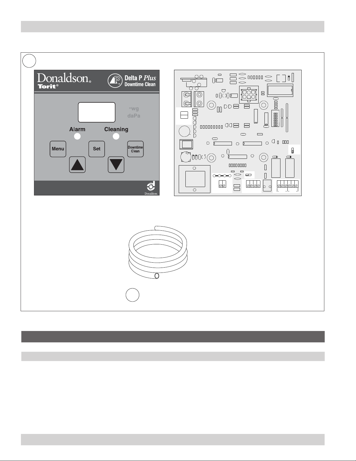
The Delta P Plus Controller monitors the differential pressure between the clean-air and dirty-air plenums, providing a visual
display of the lter condition. When combined with a pulse timer, it manages the pressure drop by turning the cleaning mechanism
On and Off at the chosen limits. There are three (3) set points: High Pressure On, Low Pressure Off, and Alarm. The rst two,
High Pressure On and Low Pressure Off, control the lter cleaning system. The third, Alarm, provides a relay output to activate an
external alarm supplied by others.
The user can program the Delta P Plus Controller to pulse while the collector is running, to maintain a relatively constant pressure
drop across the lters, pulse only after the collector is shut down (after-shift cleaning), or a combination of both, cleaning while
running as well as end of the shift.
2 Product Description
3 Operation
Three cleaning modes, Differential Pressure Cleaning (DFF), Downtime Cleaning (DTC), and Combined Differential and Downtime
Cleaning (ALL) are available with this controller and can be individually chosen by the user.
• Differential Pressure Cleaning (DFF) - When the differential pressure drop reaches the controller’s HIGH setpoint, the
controller closes an output relay initiating the cleaning cycle. When the differential pressure decreases to the LOW
setpoint, the relay opens and the cleaning cycle stops. This sequence continues as long as the collector is running,
maintaining the differential pressure drop within a specied range.
• Downtime Cleaning (DTC) – The Delta P Plus controller monitors for the differential pressure drop to exceed the LOW
setpoint. (Indicates the blower has been started). When the differential pressure drop later approaches zero (indicating
the blower has been shut down), the Delta P Plus engages the cleaning cycle for a pre-selected time. A delay timer
allows the blower to come to a stop before the cleaning cycle starts.
The delay timer and cleaning cycle durations are both user adjustable but password protected.
• Combined Differential and Downtime Cleaning (ALL) –The ALL mode combines the two functions described above,
maintaining the differential pressure drop in a specied range, then initiating a down-time cleaning cycle when the
differential pressure drop approaches zero. The downtime cleaning function can be toggled on or off from the keyboard.
Note: The DTC and ALL cleaning modes incorporate compressed air cleaning of the lters when the main collector fan is not
running. This may result in collected material “drifting” out the inlet duct of the collector. An isolation valve in the inlet duct of the
collector can reduce or eliminate that drifting.
Consideration should be made on the use of the DTC or ALL cleaning mode on small collectors where the relatively low volume
of the collector may produce pressure spikes with each pulse of the cleaning cycle. Such pressure spikes may accelerate the
fatigue, or damage of ancillary items such as pressure sensors or explosion relief panels.
Alarm
The Alarm setpoint is set to a higher setting than the High Pressure On used to start the lter cleaning cycle. It indicates situations
when the cleaning system cannot reduce the pressure drop due to cleaning system failure, lack of compressed air, or the end of
the lter’s useful life. There is a time delay prior to setting the Alarm to prevent nuisance trips. The Delta P Plus Controller also
provides an input connection for a remote Alarm reset.

Delta P Plus Control
7
4 Product Service
During any service activities there is some potential for exposure to the mist in the collector. Most mists present
safety and health hazards that require precautions. Wear eye, respiratory, head and other protection equipment
suitable for the type of mist when performing any service activities.
Use appropriate access equipment and procedures. Note the standard collector is not equipped with access
platforms unless noted on the specication drawings.
LOCK-OUT all energy sources prior to performing any service or maintenance on the equipment.
Electrical service or maintenance work must be performed by a qualied electrician and comply with all applicable
national and local codes.
This equipment may start or stop unexpectedely from a remote location. Turn power off and lock out all power before
performing service or maintenance work.
Operational Checkist
1. Visually conrm Delta P display is illuminated and displaying differential pressure.
2. Observe and address any alarm conditions.
3. If cleaning light is on, conrm that the collector is advancing through the cleaning process.

8
Donaldson Company, Inc.
Troubleshooting
Problem Probable Cause Remedy
No display on the
Delta P Plus Control
No power to the control Use a voltmeter to check for voltage at Terminal TB1.
Fuse blown Check the fuse in the F1 fuse tower. Replace if necessary.
Display on the Delta P
Plus control does not
read zero when at rest
Out of calibration Disconnect pressure tubing. See Delta P Plus Control
Calibration.
With collector discharging outside,
differential pressure is present from
indoor to outdoor
Recalibrate with the pressure tubing attached as described
in Delta P Plus Control Calibration.
Display reads “_ _ _” Pressure out of the allowable range Check that high and low pressure tubing is attached and
not leaking. Use a differential pressure measurement
device to verify that the actual pressure does not exceed
20 “wg.
Delta P Plus Control ON,
but cleaning system
does not start
Not wired to the timing board
correctly
Connect the pressure switch on the timer board to
Terminals 7 and 8 on TB3.
Faulty relay Using a multimeter, test relay for proper closure. Replace
if necessary.
Pressure tubing disconnected,
ruptured, or plugged
Check tubing for kinks, breaks, contamination, or loose
connections.
Pulse cleaning never
stops
Pressure switch terminals on the
timer board jumpered
Remove jumper wire on solid-state timer board before
wirng to Delta P Plus Control.
Pressure switch not wired to the
timer board corrrectly
Connect the pressure switch on the timer board to terminal
7 (normally open) and Terminal 8 (common) on TB3.
High or low setpoint not adjusted
for system conditions
Adjust setpoints to current conditions. See Setpoint
Adjustment.
Pressure tubing disconnected,
ruptured or plugged.
Check tubing for kinks, breaks, contamination, or loose
connections.
Alarm light is ON Alarm setpoint too low Adjust to a higher value.
Excess pressure drop Check cleaning system and compressed-air supply.
Replace lter cartridges if lters do not clean down.
Pressure tubing disconnected,
ruptured, or plugged
Check tubing for kinks, breaks, contamination, or loose
connections.

Delta P Plus Control
9
Problem Probable Cause Remedy
Delta P Plus arrow keys
do not work
Improper operation Press MENU and choose a parameter, then press SET
prior to using the arrow keys.
Programming keys disabled Remove the Program Disable jumper from Terminals 3
and 4 on TB2.
Cleaning light is ON,
but cleaning system not
functioning
Improper wiring Check wiring between the Delta P Plus Control and the
timer board, and between the timer board and solenoid
valve coils.
Defective solenoids Check all solenoid coil for proper operation.
Timer board not powered Check power ON light on timer board’s LED display. If not
illuminated, check the supply voltage to the timer board.
Check the fuse on the timer board. Replace if necessary.
Timer board defective If LEd is iluminated, observe the output display. Install a
temporary jumper across the pressure switch terminals.
Output LED’s should ash in sequence. Check ouput
using a multimeter set to 150 VAC range, measure from
SOL COM to a solenoid output. The needle will deect
when LED ashes for that output if voltage is present. If
LEDs do not ash, or if no voltage is present at output
terminals during ash, replace the board.
Downtime cleaning
too long or too short
duration
Parameter setup Reset the value in Parameter P10.
Pressure display
changes value up and
down rapidly
Parameter setup Reset the value in parameter P12.

10
Donaldson Company, Inc.
PS1
5
4 2 1
side view
autotran
BKT1
C6
R35
U6
L3
L4
L5
C16
C17
C18
R43 R42 R41
R44 R45 R46
C3
C2
Y1 D5
5 4 3 2 1
J2
U1
R50
R51
C8
R27
T36
R37
R38
RA12
U7
U2
1
2
3
4
5
6
7
8
1
2
3
4
5
1
2
3
4
5
6
7
8
RA8
RA7
RA11
ADDRESS
SW6
1
2
3
4
5
6
7
8
C14
R33 R48 R49
low
CP1
D1 D2
CR1 CR2
TB3
Mode
slave
alarm
R47
Q7
J5
7 8 9 10 11 12
hi/lo
control
alarm or
auxiliary
J3
J4
NC
2
3
NC
2
3
prog
disable alarm
reset
3 4 5 6
R26 R28 R31 R32
R25 R39 R29 R21
R22 R23
C11
C12 TB2
3 2 1
J1
in mm
L1
L2
1 2
TB1
115/230-V
input
W1 W2 W3
115V 230V 115V
UPDOWN
CP4
CP5
CP2
U4
U8
C15
high Alarm
C5 R34
R16
R15
R19
R14
Cleaning
Alarm
CP3
U3
C4
Q2
Q1
Q3
Q5
Q4
"wg
mm wg
R5 R11 R6 R8 R20
Q8 Q6
R10 R4 R9 R7
LED 1 LED 2 LED 3
LED 1-3
R1R3
Q10
R13
Q9
R12
R17
R12
R30
C13 C19 C7
VR2
U5
CONN 1
R2
R40
R24
TB4
sensor out
13
+14
GND
C10
VR1
in out
F1
D3 D4 C1 C9
7
9
10
12
T1
1
3
4
6
A144C
M9805-02-08 REV.
PJ1
1
2
3
4
5
1
2
Delta P Control
Replacement Parts
Item Part Number Description Model
1 7053601 Delta P Plus Control (includes keypad label and printed circuit board) All
2 2334200 Plastic Tubing, Vinyl, 3/16-in ID, 5/16-in OD All
Printed Circuit BoardKeypad Label
Plastic Tubing

Delta P Plus Control
11
Appendix A - Installation

12
Donaldson Company, Inc.
Delivery and Inspection
Upon arrival inspect equipment and report any damage to delivery carrier. File any damage claims with the delivery carrier.
Request a written inspection report from the Claims Inspector to substantiate all damage claims.
Compare the equipment received with the description of product ordered. Report any incomplete shipments to the delivery carrier
and your Donaldson Torit representative.
Unloading and Positioning
Equipment should be lifted only by qualied crane or fork truck operators.
Failure to lift the equipment correctly can result in severe personal injury and/or property damage.
1. Remove any crates or shipping straps.
2. Lift the packaged collector from transport container.
3. Inspect for any damage and/or missing parts and report to freight carrier.
4. Check for any hardware which may have become loose during shipment and tighten as necessary.
Installation
Location and Site Selection
Electrical Installation (including bonding and grounding of the collector) must be performed by a qualied electrician.
Do not install in classied hazardous atmospheres without an enclosure rated for the application.
Service must be performed by trained and qualied maintenance personnel.
This equipment may start or stop unexpectedly from a remote location.
Codes may regulate recirculating ltered air in your facility. Consult with the appropriate authorities having jurisdiction
to ensure compliance with all national and local codes regarding recirculating ltered air.
Equipment location must conform to all codes and standards, should be suitable fot the type of dust being handled and should
ensure easy access for service and utility connections. Site selection must account for wind, seismic zone and other load
condidtions.

Delta P Plus Control
13
Electrical installation, service, or maintenance work must be performed by a qualied electrician and comply with all
applicable national and local codes.
This equipment may start or stop unexpectedly from a remote location.
Turn power off and lock out all power before performing service or maintenance work.
The appropriate wiring schematic and electrical rating must be used. See collector’s rating plate for required voltage.
Do not install in classied hazardous atmospheres without an enclosure rated for the application.
Electrical Wiring
The Delta P Plus Control is factory set for 115-V. To operate at 230-V, the jumper settings on the printed
circuit board must be changed. See Optional Settings.
1. Choose a location near the collector that permits access to the keypad for adjustments and observation of the pressure drop.
If possible, mount the control indoors.
2. Mount the control enclosure using four self-drilling, self-tapping screws.
Use vibration isolators in high vibration areas.
3. Connect the output contacts to the correrct contact terminals of the pulse control time per the supplied electircal drawing.
These connections will start/stop the cleaning cycle.
4. Wire the auxiliary alarm circuit, if desired. This relay output can be used to activate visual or audible alarms provided by
others. If not wired, the alarm LED light on the control panel will be the only indication of a fault condition.
Use proper grounding and handling procedures to prevent permanent damage to this device. Handle the
printed circuit board by the edges only. Do not touch the socketed E2PROM pins.
5. Wire all remaining auxiliary connections at this time. See the Optional Settings for a list of these options.
6. Thirty-ve feet of plastic tubing is supplied with the control and must be cut in two sections. Connect one section of tubing from
the control enclosure’s high-pressure port to the pressure tap on the dirty-air plenum. Connect the remaining section of tubing
from the control enclosure’s low-pressure port to the pressure tap on the clean-air plenum. Additional tubing can be ordered
from your representative.
7. Apply power to the control. Set the high- and low-pressure setpoints to start and stop the cleaning process. Set the alarm
setpoint to activate the alarm display. See Control Calibration.

14
Donaldson Company, Inc.
Setpoint Adjustments
Quick Start Instructions
1. Press the MENU key, Lo appears. Press the SET key and the current value appears in the display. Use the arrow keys pq
to change this value. Press SET again, and the display will blink twice, indicating that the new set point has been accepted.
The Lo setting selects the differential pressure drop value used to stop the pulse cleaning cycle, 2.0” w.g. is a typical initial
value.
For collectors with pleated bags, it is recommended that the low setpoint be set to no lower than 0.5” w.g.
below the high setpoint.
2. Press the MENU key twice, Hi appears. Press the SET key and the current value appears in the display. Use the arrow keys
pqto change this value. Press SET again, and the display will blink twice, indicating that the new set point has been
accepted.
The Hi setting selects the differential pressure drop value used to start the pulse cleaning cycle, 4.0” w.g. is a typical initial
value.
3. Press the MENU key three times, AL appears. Press the set key and the current value appears in the display. Use the arrow
keys pqto change this value. Press SET again, and the display will blink twice, indicating that the new setpoint has been
accepted.
The AL setting selects the differential pressure drop value used to close the Alarm relay and turn on the Alarm pilot light on the
display.
4. Press the DOWNTIME CLEAN key, and the display will read either On or Off. Pressing the same key again will toggle the
reading [On to Off or Off to On]. Press the SET key to lock in your choice.
Adjustments
1. Pressing the MENU key repeatedly scrolls through the following programming choices:
Lo — Low set point
Hi — High set point
AL — Alarm set point
rtn — Return to reading current conditions
PAS — Password (for access to secured functions)
3. The SET key shows current value and locks in values after adjustments.
4. The DOWNTIME Clean button toggles the function on and off when available.
5. Not pressing any buttons for 10 seconds allows the control to return to monitoring the lter system.
Password Protected Settings
To reach the password protected settings, press the MENU key 5 times, the display will show PAS.
Press the SET key, use the up arrow key pto set the value to “4”, press set again.
When the display blinks twice, press the MENU key repeatedly until you reach the parameter you wish to change.
Once you have selected a parameter, use the arrow keys pqto change the value within the setting range shown in the table.
Press the SET key to lock in the value.

Delta P Plus Control
15
Parameters Description Setting
Range
Factory
Default Units Function
ALL ALL - Combines differential pressure (Delta P)
based cleaning with downtime cleaning ON/
OFF selectable from keypad.
P 6 Mode Select DTC ALL - - DTC - Filters downtime cleaned only, not
based on lter Delta P.
DFF DFF - Filter cleaning based on Delta P with
downtime cleaning not available.
P 7 Display Units
0 = in. w.g.
1 = daPa
0 - 1 0 - - Selects units of measure for the
digital display.
P 8 Downtime Start
Relay
30 - 99 30 Seconds Adjustable time lag between the pressure
dropping below the value set in parameter P
11 and the start of downtime cleaning.
P 9 Downtime
Pressure Enable
Relay
30 - 99 30 Seconds Adjustable time required to be above the
value set as the Low Set Point (Lo) before the
downtime feature is enabled.
P 10 Downtime
Cleaning Time
1 - 999 10 Minutes The amount of time the downtime cleaning will
continue once the time set in P 9 expires.*
P 11 Downtime Start
Pressure
0 - 9.6 (245) 0.3 (13) In. Water
(daPa)
The falling pressure that triggers the downtime
cleaning sequence. **
P 12 Pressure Sensor
Input Filtering
0 - 2 1 - - Sets the time used for Delta P value averaging
(0 = 250 ms, 1 = 2.5 sec, 2 = 10 sec).
P 13 Reset to Factory
Defaults
0 - 1 0 - - 0 = No Reset
1 = Reset
P 14 Zero Offset 0 - 1 0 - - 0 = No Operations
1 = Offset and Displayed Zero
P 15 Software Version - - - - - -
P 16 Password - - - - - - Factory password, no user adjustable items in
subsequent parameters.
* If the downtime cleaning sequence is in progress and the pressure drop indicates a fan restart, the cleaning sequence will end.
** If P 11 is set as equal to or greater than the Lo value, the Lo value will automatically increase 0.2” above the P 11 value.

16
Donaldson Company, Inc.
Delta P Plus Display
Delta P Plus Control Calibration
The only user calibration is the zero adjustment of the display. Due to slight changes in electronic components over time or
pressure within the plant environment, the display may read something other than 0.0 while at rest. Use the following procedure to
recalibrate the operating system.
1. Turn power to the Delta P Plus Control ON for a minimum of 30-minutes to stabilize the operating temperature.
2. Disconnect the pressure tubing, either leaving it to atmosphere, or connecting the two barbed ttings together with a short
length of tubing.
3. Use the Menu key to select PAS.
4. Press SET, then use the arrow keys to display “4”, press SET again.
5. Press the MENU key repeatedly until you reach P14.
6. Press SET, then use the arrow keys to display “1”, press SET again.
7. After 10 seconds with no further button action, the display will return to reading the pressure.
8. Connect one section of tubing from the control enclosure’s high-pressure port to the pressure tap on the dirty-air plenum.
Connect the remaining section of tubing from the control enclosure’s low-pressure port to the pressure tap on the clean-air
plenum.
indicates closed
alarm relay
menu
increase
setpoint
downtime clean
3-digit dieplay
indicates closed
cleaning relay
set
decrease
setpoint

Delta P Plus Control
17
Delta P Control Installation
high-pressure port
dirty-air plenum
low-pressure port
clean-air plenum

18
Donaldson Company, Inc.
Optional Settings
See Printed Circuit Board illustration.
230 VAC Power Supply
To operate at 230 VAC, remove two jumpers labeled W1 and W3. Reinsert one of the jumpers in position W2.
Change from English to Metric (SI) Units
1. Turn power to the Delta P Plus Control ON.
2. Use the Menu key to select PAS.
3. Press SET, then use the arrow keys to display “4”, press SET again.
4. Press the MENU key repeatedly until you reach P7.
5. Press SET, then use the arrow keys to display “0”, press SET again.
6. After 10 seconds with no further button action, the display will return to reading the pressure.
Disable Setpoint Adjustment
To restrict setpoint changes, install a jumper wire across the PROG. DISABLE terminals (3 & 4) on Terminal Block 2, TB2. The
current settings will still be displayed, but no changes can be made until the jumper is removed. Interrupting the jumper with a
key-operated, normally-closed switch installed in the enclosure door provides temporary access to the setting functions without
opening the door.
External Alarm Reset / Disable (TB2, Terminal 5 & 6)
If desired, wire the ARM RESET terminals (5 & 6) on Terminal Block 2, TB2, to a key-operated, normally-open switch. Closing the
switch turns the alarm OFF.
Internal Alarm Disable (J5)
To disable the alarm internally, remove the jumper on MODE Jumper Block J5, located on the lower-right quadrant of the circuit
board. Disabling the alarm relay reduces the alarm function to the ALARM LED visual display only.
Hi/Lo Control (TB3, Terminals 7, 8, & 9)
Per the wiring diagram supplied with the controller, the Hi/Lo terminals are connected to the pressure switch input on the timer
board. In most cases this connection is made at the factory.
Terminal 8 is common, terminal 7 is normally open, and terminal 9 is normally closed.
Auxiliary Relay Output (TB3, Terminals 10, 11, & 12)
1. If the jumper on the MODE Jumper Block J5 is not installed, the auxiliary relay output will not function.
2. If the jumper is installed in the ALARM mode position, the auxiliary relay output activates based on the setting of the ALARM
setpoint.
3. If the jumper is installed in the SLAVE mode position, the auxiliary relay output activates in parallel with the HI/LO CONTROL
relay.
Terminal 11 is common, terminal 10 is normally open, and terminal 12 is normally closed.
Analog Output (TB4, Terminals 13 & 14)
Terminals 13 & 14 on Terminal Block 4, TB4, in the upper-left quadrant of the circuit board, provide a 4 to 20 mA output
proportional to the 0-to-maximum span of the pressure sensor. This circuit requires a 500 ohm maximum load.

Delta P Plus Control
19
Printed Circuit Board (Optional Settings Location)
PS1
5
4 2 1
side view
autotran
BKT1
C6
R35
U6
L3
L4
L5
C16
C17
C18
R43 R42 R41
R44 R45 R46
C3
C2
Y1 D5
5 4 3 2 1
J2
U1
R50
R51
C8
R27
T36
R37
R38
RA12
U7
U2
1
2
3
4
5
6
7
8
1
2
3
4
5
1
2
3
4
5
6
7
8
RA8
RA7
RA11
ADDRESS
SW6
1
2
3
4
5
6
7
8
C14
R33 R48 R49
low
CP1
D1 D2
CR1 CR2
TB3
Mode
slave
alarm
R47
Q7
J5
7 8 9 10 11 12
hi/lo
control
alarm or
auxiliary
J3
J4
NC
2
3
NC
2
3
prog
disable alarm
reset
3 4 5 6
R26 R28 R31 R32
R25 R39 R29 R21
R22 R23
C11
C12 TB2
3 2 1
J1
in mm
L1
L2
1 2
TB1
115/230-V
input
W1 W2 W3
115V 230V 115V
UPDOWN
CP4
CP5
CP2
U4
U8
C15
high Alarm
C5 R34
R16
R15
R19
R14
Cleaning
Alarm
CP3
U3
C4
Q2
Q1
Q3
Q5
Q4
"wg
mm wg
R5 R11 R6 R8 R20
Q8 Q6
R10 R4 R9 R7
LED 1 LED 2 LED 3
LED 1-3
R1R3
Q10
R13
Q9
R12
R17
R12
R30
C13 C19 C7
VR2
U5
CONN 1
R2
R40
R24
TB4
sensor out
13
+14
GND
C10
VR1
in out
F1
D3 D4 C1 C9
7
9
10
12
T1
1
3
4
6
A144C
M9805-02-08 REV.
PJ1
1
2
3
4
5
analog
sensor
out
voltage jumpers
power connection
alarm
disable
change units
external alarm reset
disable setpoints

Service Notes
Date Service Performed Notes
20
Donaldson Company, Inc.
Model Number _________________________________ Serial Number ___________________________________
Ship Date _____________________________________ Installation Date __________________________________
Filter Type_____________________________________________________________________________________
Collected Dust _________________________________________________________________________________
Dust Properties: Kst _______________Pmax ______________ MIE ____________ MEC __________________
Accessories ___________________________________________________________________________________
Other ________________________________________________________________________________________
_____________________________________________________________________________________________
Product Information (Process Owner to complete and retain for your records)
Other manuals for Delta P Plus
1
Table of contents
Other Donaldson Torit Control Panel manuals