Combustible materials such as buffing lint, paper, wood, metal dusts, weld fume, or flammable
coolants or solvents represent potential fire and/or explosion hazards. Use special care when
selecting, installing, and operating all dust, fume, or mist collection equipment when such combustible
materials may be present in order to protect workers and property from serious injury or damage due to a
fire and/or explosion.
Consult and comply with all National and Local Codes related to fire and/or explosion properties of
combustible materials when determining the location and operation of all dust, fume, or mist collection
equipment.
Standard Donaldson Torit equipment is not equipped with fire extinguishing or explosion protection systems.
1
Donaldson Company, Inc.
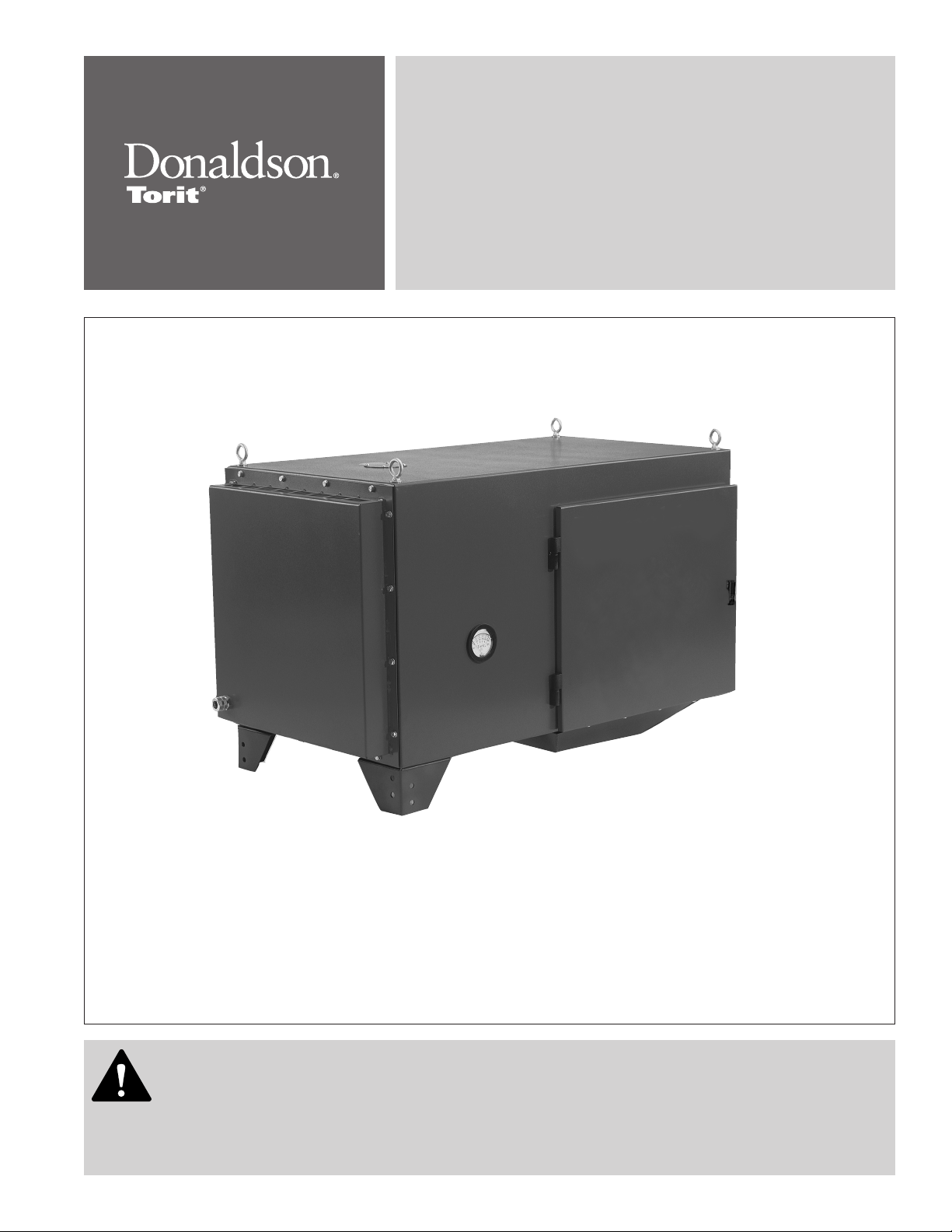
Description
Designed for versatility, the WSO M (Water, Smoke, and
Oil) mist collector is specifically engineered for water-
soluble, smoke, and oil-based mist applications. WSO
M mist collector, Machine-Mountable Model collects
airborne mist such as oil, water-soluble, semi-synthetic
and synthetic coolant from machining operations. Two
stages of filtration, plus an optional HEPA or 95% DOP
filter, provide a cleaner, healthier work environment as
well as a more cost effective means of mist collection.
With clean filter airflow capacities of 520 cmh (306
cfm) @ 50 Hz and 660 cmh (388 cfm) @ 60 Hz, the WSO
M is a strategic component to meeting industrial and
government air-quality standards. The high efficiency
filter cartridges allow air and coolants to be recycled.
Designed to increase the versatility of the unit, a variety
of filter media specifically designed for mist collection
is a standard offering on the product line. The primary
filter is uniquely designed for either water-based
coolants, straight oils, or thermally-generated smoky
applications. Standard options include drain collection
containers, adjustable floor mounting stands, and
afterfilters.
The WSO M machine-mountable unit is powered by a
blower and motor mounted in the filter cabinet.
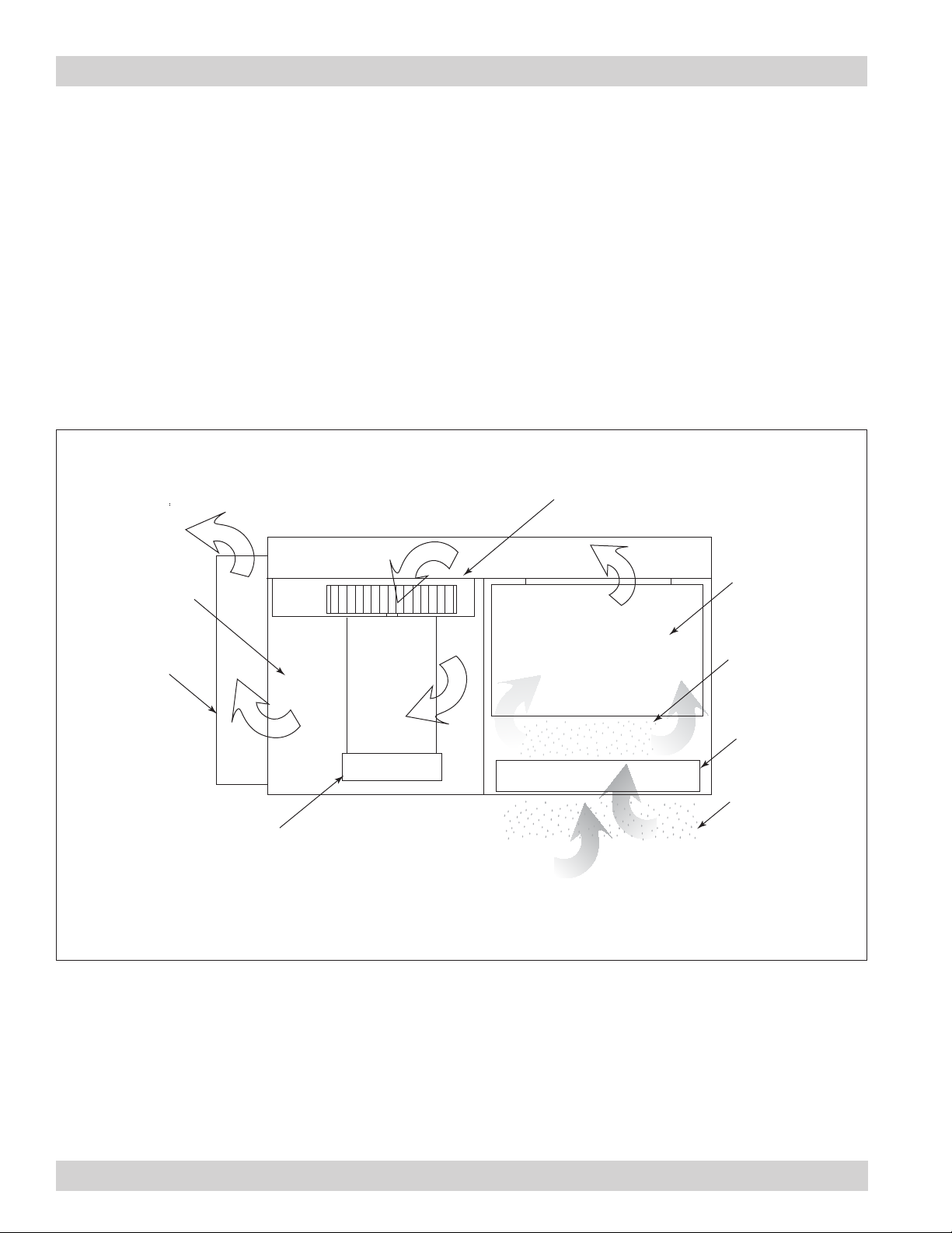
Airborne mist is small droplets of metalworking fluids
suspended in the air. Metalworking fluids include
straight oils, water-soluble coolants, semi-synthetic
synthetic coolants. These fluids perform a variety of
functions such as lubricating or cooling the part or the
tool, flushing chips away from the part, and suppressing
dust and smoke.
Mist is created in two ways: mechanical action or
thermal effects. Mechanical action involves coolant
used for light lubrication and generally creates mist
greater than one micron in size. Thermal effects occur
when heat vaporizes the coolant, the vapor cools and
recondenses into a mist. Thermal effects create mist
from 0.01 to 1 micron in size. Other contaminants, such
as dust from the part or the tool or smoke from the
vaporization of the oil or coolant are also generated
when using metalworking fluids.
The WSO M mist collector is not designed to handle
water mist alone. There should be some type of oil
content to allow coalescing since water vapor will
simply pass through the filters. The extremes of very
heavy oil and light, thin oil should be avoided. Very heavy
oil, similar to tar consistency, will not drain while very
light, thin oil, similar to paint thinner consistency, may
evaporate.
Purpose and Intended Use
Misuse or modification of this
equipment may result in personal
injury.
Do not misuse or modify.