With DT-CAM wiring mode - NOT available from Doorentryonline Ltd
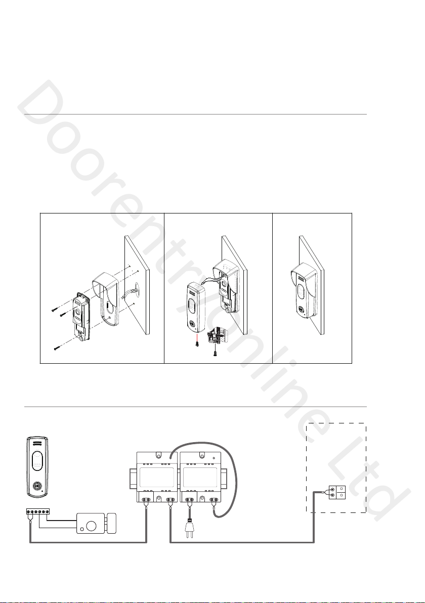
Electric Lock Connecon
Door Lock Controlled with Internal Power
Door Lock release connected with additional power supply
Note:
1. Electronic lock of Power-on-to-unlock type
should be used.
2. The door lock is limited to 12V, and holding
current must be less than 250mA.
3. The door lock control is not timed from Exit
Button (EB).
4. The Unlock Mode Parameter on the Monitor must
be set to 0 (This is default).
EB
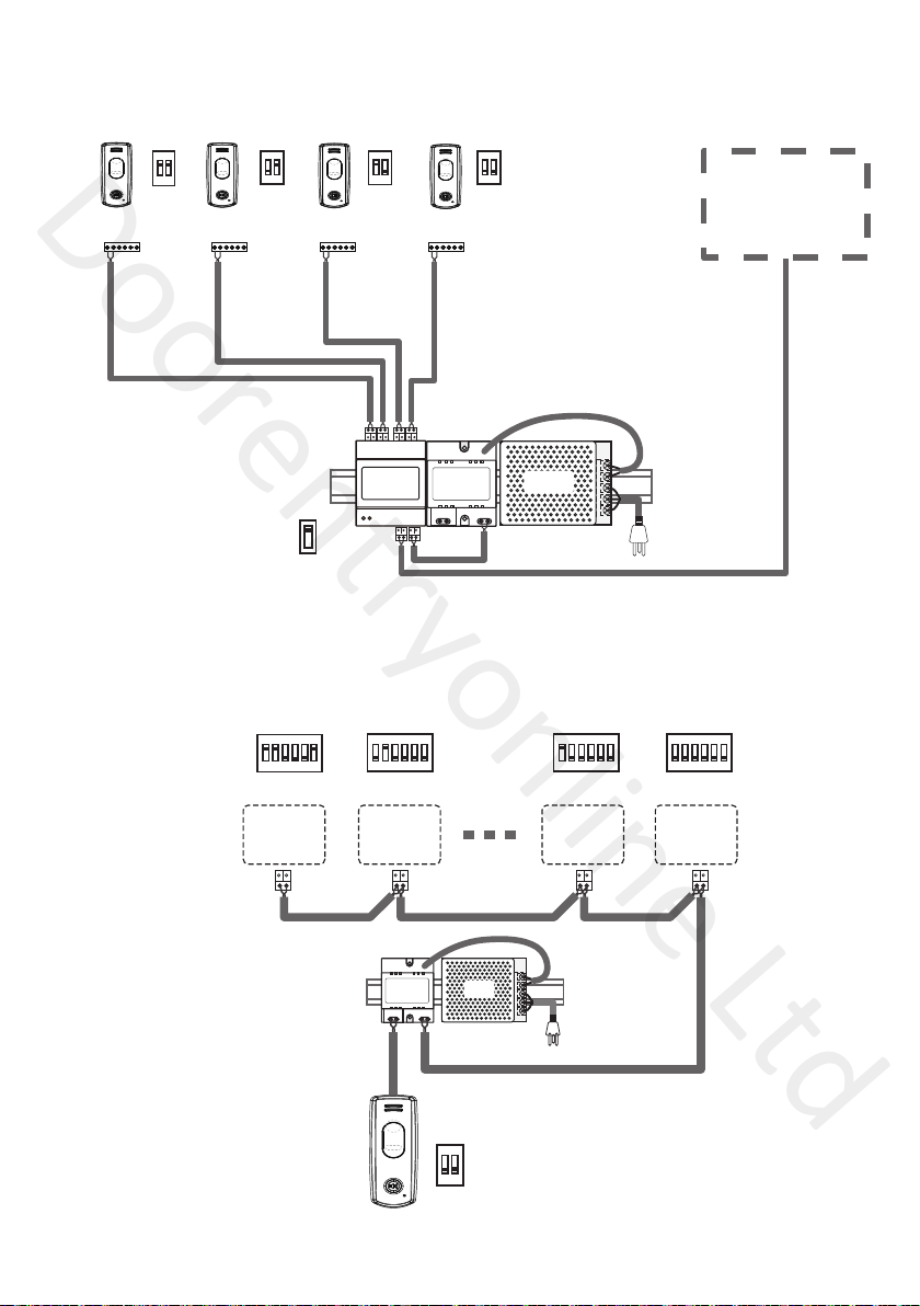
*LOCK
Jumper position in
Connect one lock
2-3
Bus PL S2+ S1+ S1-
Note:
1. The external power supply must be used
according to the lock.
2. The jumper must be taken off before connecting.
3. Setup the Unlock Mode of Monitor for different
lock types.
* Power-on-to-unlock type:Unlock Mode=0 (This is default)
* Power-off-to-unlock type:Unlock Mode=1
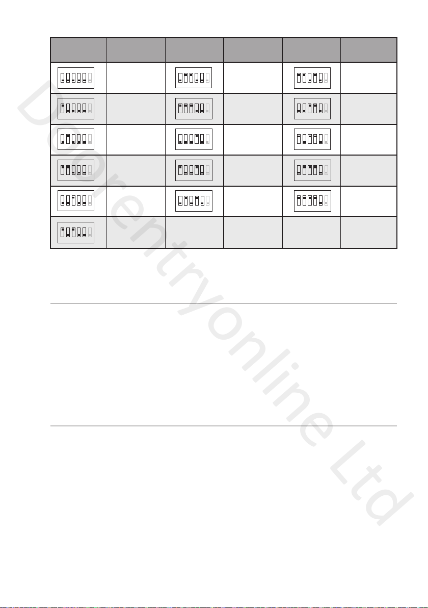
DIP Switch Settings
The DIP switch is designed to set the code for door panel and monitor, there are two states for
each DIP switch, please refer to the following:
The audio door station DT595A can be extended an additional CCTV camera to be a video door
station. For more details about the camera, please refer to DT-CAM user instructions.
Door panel DIP setting
Indoor monitor DIP setting
Bit state Description
ON(1)
=
OFF(0)
=
ON
ON
Total of 3 bits can be configured, bit-1 and bit-2 are used to assign the ID code for the door panel, bit-3
is used to match the video impedance.The switches can be modified either before or after installation.
There are 6 bits in total. The DIP switches are used to configure the user code for Monitors.
Bit-6 is an video impedance match switch, which have to be set to ON if match the impedance,
otherwise set to OFF.
Bit-1~Bit-5 are used to set the user code to the door panel, the user code should set from 0-15.
Please refer to the following settings:
Note: if the video impedance needs to be matched, please set the bit-3 on.
123
ON
123
ON
123
ON
123
ON
ID = 0(00), set for the first door panel
ID = 1(10), set for the second door panel
ID = 2(01), set for the third door panel
ID = 3(11), set for the fourth door panel
LOCK
Take off theJumper
POWER
SUPPLY
Bus PL S2+ S1+ S1-
1 2 3
AC~
PC6
ERL
DT595A
DT-CAM
DS IM
Bus PL S2+ S1+ S1-
OUT IN
Monitor
-8-