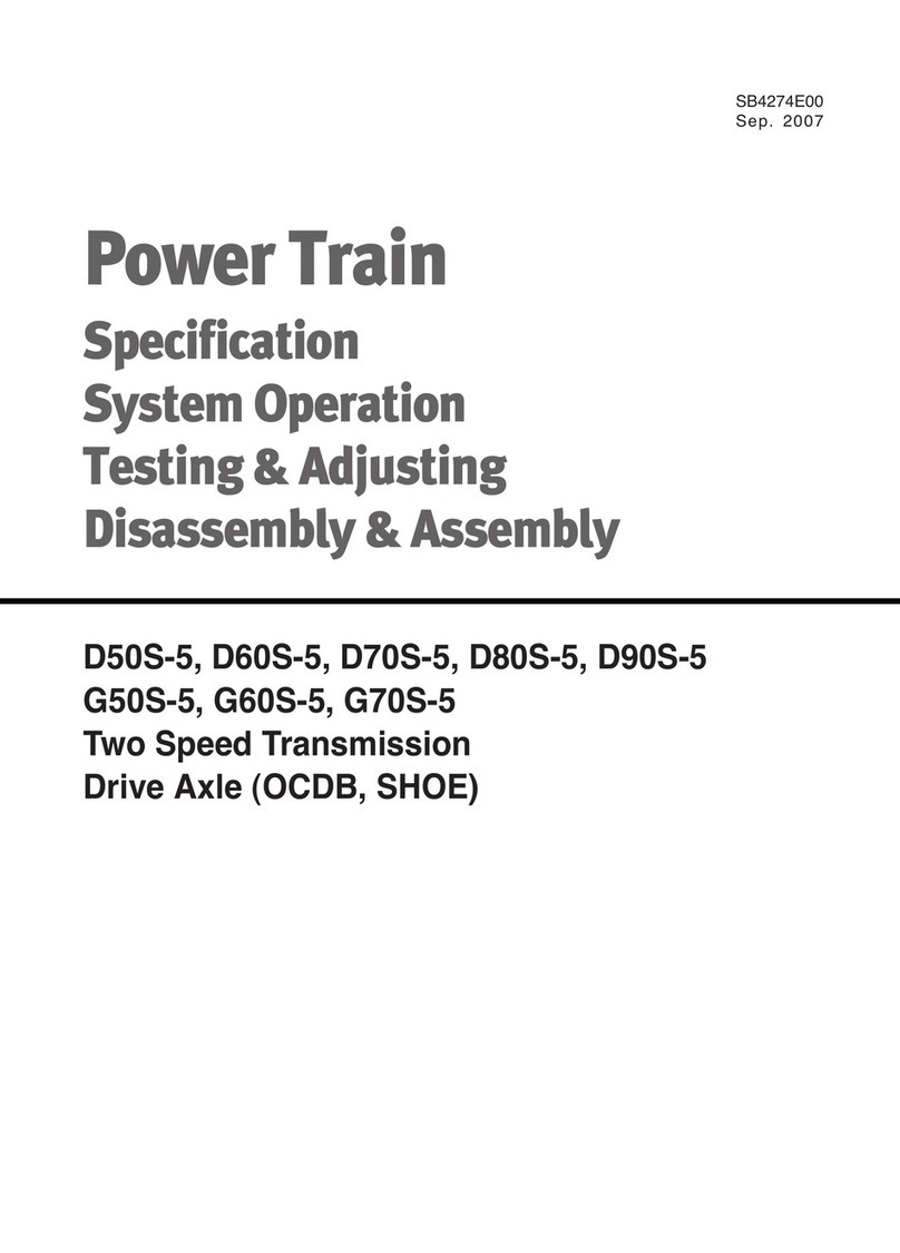
Doosan HP5100 Guide

Machine Tools
HMC
Maintenance
(HP5100)

124
HP5100 HP51MTE87
Contents
No. Alarm
number
Alarm Name Page
1 2001
OP Emg. Stop PB or LS Off
126
2 2002
Main Spindle Servo Alarm
128
3 2003
Circuit Protector Tr
ip
130
4 2004
Hyd. Pump Motor Overload
132
5 2005
Hyd. Pressure Down Alarm
1
34
6 2009
ATC
Servo or Inverter Alarm
137
7 2010 Spindle Tool Unclamp Cmd. Fault
138
8 2015 Spindle Tool Unclamp Alarm
140
9 2020 Coolant & Lub. Pump Overload
142
10 2021 Air Pressure Down Alarm
175
11 2023
M06 Command Overtime Alarm
162
12 2036
Magazine Rotation or Matrix Illegal Position Alarm
167
13 2037 M06 Command Illegal Pos.
171
14 2041 APC Overtime Alarm
173
15 2042
M61 / M62 Command Illegal Position
176
16 2048
ATC
Door Open
180
17 2050
Lub. Level Low or
Pressure Down
184
18 2051
Oil cooling Unit Alarm
186
19 2052
Filter Change Alarm For TSC Unit
195
20 2060 Spindle Tool CL/UNCL Overtime Alarm 196
21 2063 ATC Arm Pin Alarm 198
22 2064 Waiting Tool Pot Spindle/Magazine Side Alarm 200
23 2065 Changer Arm Position Check Alarm 203
24 2073 Pallet or Table CL/UNCL Switch Alarm 207
25 2074 ATC Overtime Alarm 211
26 2075 ATC Magazine Rotation Over Time Alarm 215
27 2077 Waiting Pot & Spindle Tool No. Zero 218
28 2078 ATC OP Manual Mode 220
29 2080 ATC or APC Interlock Alarm 222
30 2081 ATC Magazine Guard Door Open 226
31 2084 APC Set-Up Station Door Open 228

125
HP5100 HP51MTE87
No. Alarm
number
Alarm Name Page
32 2085 APC Set-Up Location S/W Unpush 229
33 2086 APC OP Manual Mode 231
34 2090 Table Or Pallet Clamp Alarm 233
35 2094 Chip or Screw Conveyor Alarm 236
36 2107 Operator’s Door Open 238
37 2118 Operator’s Door Open Alarm 239
38 2120 Y-Z Interference Zone Alarm 241
39 2126 APC Up / Down Alarm 243
40 2127 APC Changer 180CW/CCW Alarm 246
41 2154 Waiting Pot Clamp Alarm 249
42 2155 Tool Magazine Pot Detect Switch Alarm 251
43 2158
Waiting Pot Spindle/Magazine Side Command
254
44 2160 APC Pallet Check Switch Alarm 256
45 2163 ATC Door Open/Close Alarm 258
46 2200 T-code Or M06 Commanded Status 260
47 2215 VPF Off Of Tool Magazine 261
Appendix1
X-Y Signal Address 263
Appendix2
M-CODE LIST 268
Appendix3
Repairing Method of Spindle Amp Alarms 274
Appendix4
ATC Main Changer Sequence Chart 280
Appendix5
Pallet Change Sequence Chart 281
Appendix6
Recovering ATC Breakdowns 283
Appendix7
Repairing Method of Servo Driver Alarms 286

126
HP5100 HP51MTE87
OP Emg. Stop PB or LS Off
Either the Emergency Stop Push Button Switch has been pressed on the
operation panel, or more than one of
Emergency Stop Axis Limit Switches
of each axis have been activated.
①
The Emergency Stop Push Button Switch has been pressed on the
operation panel (Main O.P, ATC O.P).
②
The Axis (X,Y,Z Axis) Emergency Stop Limit Switch has been pressed.
③
The operation panel Emergency Stop Switches,
axis emergency stop
Limit Switches, or other related parts are faulty.
④
The connecting cable has been disconnected.
①
Check if the red spade-
shaped push button switch has been pressed on
the operation panel (Main O.P, ATC O.P). If it is pressed
, turn the
switch clockwise to release it.
②
When each axis's(X, Y, Z Axis) emergency stop Limit Switch has been
activated, simultaneously press the operation panel Machine Ready
Switch and the Emergency Release Switch to set the machine
at
Machine Ready. (If the switch is released, the machine returns to
emergency status.) Transfer the problem axes in Jog or Handle Mode
to release it from the axis emergency stop Limit Switch.
③
Check the operation panel Emergency Stop Switches, axis eme
rgency
stop Limit Switches, or other related parts for problems. Make any
necessary replacements or repairs.
④
Connecting Cable Disconnection: Refer to the Electric drawings
and use
a Electric tester to check the Terminal Block for each terminal to find
the problem area. Connect the cable or replace with a new cable.
Part Name Part Number
Symbol Model Maker
Switch, Emergency P/B
(for Main) ESWPB0439 SB1 B130-81L 2B KACON
Switch, Emergency P/B
(for ATC) ESWPB0226 SB7 KH-3046ER-RED
Kunhung
Switch, Emergency P/B
(for APC) ESWPB0248 SB9 AH30-VR02 Fuji
Solution
Cause
Status
2001

127
HP5100 HP51MTE87
Signal Address
Symbol I/O Status Connector
(Pin)
Numbering
Tube
Emergency
Stop
X8.4
ESP.M
-SB1,124,SEMG,
SL1,2,3,12A,13A,
15ª
Input Module
Slot 02 T/Block(31) ESP
Machine
Ready
X32.4
MRD.M -SB11 Distr
ibuted I/O
Module A XC56A(A04) SB11
ddress Symbol Coil Comment
A0.0 2001 OP Emg. Stop or LS Off
R650.2 APONI Auto Power On Initial Flag
R652.7 ARST Upper Alarm Reset
X8.4 ESP.M Emergency Stop
X32.4 MRD.M Machine Ready
OP Emg. Stop PB
or LS Off

128
HP5100 HP51MTE87
Main Spindle Servo Alarm
The Alarm shows on the Main Spindle Drive Unit
①
Main Spindle Drive Unit troubled
②
The Spindle Motor, power cable, or signal cable troubled
Check the Alarm number appearing in the Main Spindle Drive Unit on
①
the operation panel
Take appropriate
②
actions according to the alarm number.
Refer to appendix (Repairing Spindle Amp Alarms)
☞
Check the spindle motor three
③
-phase power and Feedback cable
connections
Actions
Cause
Status
2002

129
HP5100 HP51MTE87
Address Symbol Coil Comment
A0.1 2002 Main Spindle Servo Alarm
F45.0 ALMA Spindle Alarm
R652.7 ARST Alarm Reset
Main Spin
dle
Servo Alarm

130
HP5100 HP51MTE87
Part Name Part Number
Symbol Model Maker
Protector, Auxiliary ENFBX0290S
QF14,15,22,
QF23,27,28,81
5SX9100
INO+1NC(6.0A)
Siemens
Protector, Circuit ENFBX0283S QF14 5SX2216-7 Siemens
Protector, Circuit ENFBX0284S QF15 5SX2220-7 Siemens
Protector, Circuit ENFBX0268S QF21 5SX2106-7 Siemens
Protector, Circuit ENFBX0264S QF22,81 5SX2101-7 Siemens
Protector, Circuit ENFBX0551 QF28 5SX2125-7 Siemens
Protector, Circuit ENFBX0278S QF27 5SX2206-7 Siemens
Signal Address
Tool Symbol I/O Connector
(Pin)
Numbering
Tube
Circuit Protect Trip
X2.3
TRIP.M
-QF
14,15,21,22,
23,81,27,28
Input
Module
Slot 07
T/Block(07)
TRIP
Circuit Protector Trip
Circuit Protect has been activated in the electrical cabinet.
①
Circuit Protect has been activated. (Detection
of abnormal electric
current)
②
Control power faulty
③
Circuit protect faulty
①
Find the reason for tripping the Circuit Protector.
☞
(ex) If QF22 has been tripped, first check for short-
circuiting in the
QF22's secondary L+ c
able. After repairing, replace the tripped Circuit
Protector.
②
If the alarm shows
without tripping the circuit protector, measure
resistance at each auxiliary a contact to find the short-
circuited Circuit
protector, and replace it with a new one.
☞
The normal resistance measure for contact
points when Circuit
Protect is On is “0”Ohm.
③
Check the I/O board: If
①
~
②
are normal, the I/O board is faulty.
Solution
Cause
Status
Circuit Protector
Trip
2003

131
HP5100 HP51MTE87
Address Symbol Coil Comment
A0.2 2003 Circuit Protector Trip
R652.7
ARST Alarm Reset
X2.3 TRIP.M Emergency Stop
TRIP -Q F23 A C 100V C ontrol
-Q F14 T ranse Form er P ower TR IP E
T RIPA -Q F81 A T C Motor B rak e
-Q F21 D C 24V Control T R IPD TR IP F
T RIPC -Q F28 S ole noid D C Power S ource
-Q F22 T ool M agazine M otor Brake TRIP H
1L+
Circuit P rotector T rip
15
X2.3 (T RIP .M )
In put M odule(AID 3 2E) : Slot 7
Circuit Protector Trip
Input Module(AID32E) :Slot
X2.3 (TRIP.M)
15

132
HP5100 HP51MTE87
Hyd. Pump Motor Overload
Overcurrent detected in the Hyd. Pump Motor.
①
Burnout of the Hyd. Pump Motor or power Cable
②
Fault in the Load Setting value of the Overcurrent
Detecting circuit
breaker or the Circuit Breaker itself
①
Check the Hyd. Pump Motor or Power Cable. If there are problems,
repair or replace with a new one.
②
Check the load Setting value of the Overcurrent
Detecting circuit
breaker. If it
is wrong, reset it. If the circuit breaker itself is faulty,
replace with a new one
. (The problem circuit breaker can be found by
the KA11 contact and and 1L+ contact and resistance check)
☞
QM31 Setting Overload: 2.2Kw : 9.6A
QM32 Setting Overload: 2.2Kw : 10.0A
QM36 Setting Overload: 2.2Kw : 10.0A, 3.7Kw : 17A
Product Product # Symbol Model Maker
Breaker, Auxillary
ENFBX0290R
QM31, 32 3RV1901-1F(2NO) Siemens
Breaker, Circuit ENFBX0285R
QM31, 32 3RV1011-1KA10(9-
12A) Siemens
Signal Address Tool
Symbol
I/O Connector
(Pin)
Numbering
Tube
Hydraulic Motor
Overload
X2.1
HOL.M -QM31 Input Module Slot 07
XJ411 (32)
HOL
z
Address Symbol Coil Comment
A0.3 2004 Hyd. Pump Motor Overload
R652.7
ARST Upper Alarm Reset
X2.1 HOL.M Hydralic. Motor Overload
Solution
Cause
Status
Hyd. Pump Motor
Overload
2004

133
HP5100 HP51MTE87
-Q M 31 H yd. P um p M otor(M ain)
HO LA
-Q M 32 H yd. P um p M otor(PM G )
HO LB
-Q M 36 Fixture H yd. P um p M otor
1L+
32
X2.1 (HO L.M )
Inp ut M od ule(AID32E) : Slo t 7
Hyd. P um p M otor O v erload
Input Module(AID32E) : Slot7
X2.1 (HOL.M)
XJ411 (32)
Hyd. Pump Motor Overload

134
HP5100 HP51MTE87
Hyd. Pressure Down Alarm
The Hyd. Pressure Switch has been activated because the pressure in the
Hyd. Power Unit has fallen below the Hyd. Pressure Switch set point.
①
Hyd. Power Unit malfunction
, or the oil pressure has fallen below 20
kg/
㎠
.
②
Hyd. Pressure Switch or other parts faulty
①
Turn the Hyd. Power Unit pressure adjustment valve clockwise to set
the pressure at 50Kg/
㎠
.
②
Hyd.Power Unit, Pressure Switch itself,cables, or related parts faulty.
Check Hyd. Power Unit, Pressure Switch, all cables
between Switch and
the operation panel and input modules.
Repair or replace with new
ones.
Signal Address
Tool
Symbol
I/O Connector
(Pin)
Numbering
Tube
Hyd.Pressure
Check
(Main)
X3.0
HPRS.M
-SP01 Input Module Slot
07 XJ411 (12) SP01
Hydraulic 1,2,3
Motor Run
Y38.4
HYDM.R
-KA31 Distributed I/O
Module B XCE57B(A18)
KA31
Solution
Cause
Status
Aux. Hyd. Pressure
OK Flag
Hyd. Pressure
Down Alarm
2005

135
HP5100 HP51MTE87
Address Symbol Coil Comment
A0.0 2001 OP Emg. Stop PB or LS Off
A0.1 2002 Main Spindle Servo Alarm
A0.2 2003 Circuit Protector Trip
A0.3 2004 Hyd, Pump Motor Overload
A0.4 2005 Hyd. Pressure Down Alarm
A0.6 2007 Spindle Stop Signal Alarm
A0.7 2008 -
A1.0 2009 Spindle Servo or Inverter Alarm
A1.6 2015 Spindle Tool Unclamp Alarm
F0.6 SA Servo Ready
F1.0 AL NC Alarm
K5.0 KHPRS Hyd. Pressure Switch Not Used
K11.7 KFXHYD When Motor Of Hyd. Fixture Used
Hyd. Pump On
Check Time
Hyd. Pressure
Check Time (Main)
Hyd. Pressure OK

136
HP5100 HP51MTE87
Address Symbol Coil Comment
R440.2 TMB99 Hyd. Pressure Check Time (Fixture)
R441.2 KMB107 Hyd. Pressure D-Time Initial
R625.3 TMB20 Hyd. Motor On Check Time Delay
R629.2 KMB51 Hyd. Pressure Check Time (Main)
R630.0 MRYA Aux. Machine Ready
R630.3 HPOK Hyd. Pressure OK
R647.0 APOFF Auto Power Off
R652.7 ARST Alarm Reset
R763.6 MAPCFG Man APC Command Flag
R841.0 APOKF Aux. Hyd. Pressure OK Flag
R1420.7 PMGSEL PMG Operation Selected
X3.0 HPRS.M Hyd. Pressure Check (Main)
Y38.4 HYDM.R Hyd. 1,2,3 Motor Run

137
HP5100 HP51MTE87
ATC Servo or Inverter Alarm
The alarm shows on the inverter of the Servo Motor driving the ATC
①
Servo Motor Inverter troubled
②
Servo Motor or Connection cable troubled
Refer to the Servo Motor Manual and
Repair troubled part or replace with
new ones.
☞
Refer to the Appendix (Repairing method by
Servo Driver
Alarms)
Signal Address
Tool
Symbol
I/O Connector
(Pin)
Numbering
Tube
ATC Servo or
Inverter Alarm
X9.6
TALM.M
-A81 Input Module Slot
08 XJ412 (01)
TALM
Address Symbol Coil Comment
A1.0
2009 ATC Servo or Inverter Alarm
K7.6
KATC
ATC Not Used
R652.7 ARST Alarm Reset
X9.6
TALM.M
ATC Servo or Inverter Alarm
Solution
Cause
Status
ATC Servo or
Inverter Alarm
2009

138
HP5100 HP51MTE87
Spindle Tool Unclamp Cmd. Fault
The
clamp/unclamp command signal in the spindle tool during M06
troubled. T
he tool clamp command signal is confirmed before the
unclamp command signal.
①
Fault in the unclamp command signal from ATC servo amp.
②
Error in the ATC Servo amp parameters input
①
. Check the signal cable connections for
unclamp command from
ATC servo amp
②
Check
the parameters for the ATC Servo Amp Unclamp command
location control
Signal Address
Tool
Symbol
I/O Connector
(Pin)
Numbering
Tube
Tool Clamp
Command
X8.5
(CLMD.M)
-SX51 Input Module Slot
08 XJ412 (38)
SX51
Tool Unclamp
Command
X8.6
(ULMD.M)
-SX52 Input Module Slot
08 XJ410 (22)
SX52
Solution
Cause
Status
2010
▣PARAMETERS FOR ATC SERVO
67 CLAMP POSITION (*1) 1~360 289 D277 (270)
68 UNCLAMP POSITION 1~360 25 D25
NO.67 "289" -> "277" : CHANGE DC24V SOL. (INCLUDE DIODE)
NO.69 "289" -> "284" : CHANGE DC24V SOL. (INCLUDE DIODE)
note *1) ( ) used HSK Tool
NO. ATC SERVO DEF. TYPE
FUNCTION
RANGE
HP51
HP41

139
HP5100 HP51MTE87
Address Symbol Coil Comment
A1.1 2010 Spindle Tool Unclamp Cmd. Fault
K7.6 KATC ATC Not Used
R652.7 ARST Alarm Reset
R0705.5 TCFLT Tool Clamp Command Fault
F0.6 SA Servo Ready
R652.6 ERST External Reset
R705.4 TUCCFG ATC Unclamp Command Flag
R705.5 TCFLT Tool Clamp Command Fault
R2409.0 M06CDF M06 Command Flag
X8.5 CLMD.M Tool Clamp Command
F0.6 SA Servo Ready
R705.4 TUCCFG ATC Unclamp Command Flag
R2409.0 M06CDF M06 Command Flag
X8.6 ULMD.M Tool Unclamp Command
Tool Clamp
Command Fault
Tool Clamp
Command Fault
Tool Clamp
Command Fault
Spindle Tool Unclamp
Cmd. Fault

140
HP5100 HP51MTE87
Spindle Tool Unclamp Alarm
The Spindle Tool Clamp Detection Switch i
n the Spindle Tool Clamp Status
(Spindle Tool Unclamp Output
Off) is off, or the Spindle Tool Unclamp
Detection Switch is On
①
Fault
in the adjustment of the Spindle Tool Clamp Detection Switch or
the Spindle Tool Unclamp Detection Switch
②
Fault in the Switch itself or the connection cable, or related parts
①
Readjust the Switch
②
Check the proximity Switch, connecting cable, and I/O board.
Repair
faulty part or replace with new ones.
Product Product #
Symbol Model Label
Switch, Proximity /
PNP ESWPX0265
- BES516-325-E5-C-S4
Balluff
Cable, Proximity S/W
ECBLS0170F
-SX11/12 BKS B20-1-
03
Balluff
Signal Address
Tool
Symbol
I/O Connector
(Pin)
Numbering
Tube
Spindle Tool Clamp
X6.4
TCL.M -SX11 Input Module Slot
08 XJ412 (31)
SX11
Spindle Tool
Unclamp
X6.5
TUCL.M
-SX12 Input Module Slot
08 XJ411 (47)
SX12
Solution
Cause
Status
2015
0.8~1.2mm
Proximity
Switch
Dog
Spindle Tool
Clamp
Spindle
Tool
Unclamp
Spindle Tool
Unclamp Alarm

141
HP5100 HP51MTE87
Address Symbol Coil Comment
A1.6 A1.6 Spindle Tool Unclamp Alarm
R652.7
ARST Alarm Reset
R841.2
SPTCLF Spindle Tool Clamp Flag
X6.4 TCL.M Spindle Tool Clamp
X6.5 TUCL.M Spindle Tool Unclamp

142
HP5100 HP51MTE87
Coolant & Lub. Pump Overload
Overcurrent detected in the coolant or lubricant Pump Motor.
①
Burnout of the coolant or lubricant Pump Motor or power cable
②
Fault in the Overcurrent detecting Circuit Breaker Load settting value
,
or the circuit breaker itself
①
Check the coolant or lubricant Pump Motor and power Cable.
Repair
faulty part or replace with new ones.
②
Check the Overcurrent detecting Circuit Breaker Load settting value
and reset it
. If there is a problem with the circuit breaker itself, replace
with a new one.
☞
QM10 (Spindle & Y-Axis Servo Fan Motor Use) Setting Overload: 1.5A
QM40 (Flushing Coolant Pump Motor Use) Setting Overload: 8.0A
QM41 (Flood Coolant Pump Motor Use) Setting Overload: 8.0A
QM51 (Lub. Pump Motor Use) Setting Overload: 0.9A
Product Product # Symbol Model Label
Breaker, Motor Circuit
ENFBX0255R
QM10 3RV1011-1AA10
(1.0-1.6A) Siemens
Breaker, Motor Circuit
ENFBX0258R
QM40 3RV1011-1GA10
(4.5-6.3A)
Siemens
Breaker, Motor Circuit
ENFBX0259R
QM41 3RV1011-1JA10
(7.0-10.0A) Siemens
Breaker, Motor Circuit
ENFBX0254R
QM51 3RV1011-0JA10
(0.7-1.0A) Siemens
Breaker, Auxillary ENFBX0290R
QM10,40,41,51
3RV1901-1F(2NO)
Siemens
Signal Address
Tool
Symbol I/O Connector
(Pin)
Numbering
Tube
Coolant & Lub.
Motor
Overload
X2.2
MOL.M -QM10~
-QM185 Input Module Slot 07
XJ410 (48)
MOL
Solution
Cause
Status
Coolant & Lub. Pump
Overload
2020
Other manuals for HP5100
2
Table of contents
Other Doosan Control Unit manuals