Doosan DVF5000 User manual

Manual for VMC Installation
and Commissioning
DVF5000
DOOSAN Machine Tool
MV0111ISE203


1
CONTENTS
CONTENTS
1. Preparation Before Machine Shipping
..................................................................... 4
1.1 Selection of Machine Installation site .............................................................. 4
1.2 Foundation Work.......................................................................................... 7
1.3 Preparation Before Machine Arrival ................................................................10
2. Machine transport and checking of shipped items
..................................................11
2.1 Machine Transport.......................................................................................11
2.2 Checking of shipped items ...........................................................................14
3. Machine Anchoring Operation
...............................................................................17
3.1 Machine Homing Operation...........................................................................17
3.2 Machine Anchoring Operation .......................................................................18
4. Machine Power-up
................................................................................................24
4.1 Oil Cooler Connection..................................................................................24
4.2 Disassembling the Shipping Fixtures ..............................................................26
4.3 Main Power and Pneumatic input..................................................................29
5. Machine Leveling
.................................................................................................32
5.1 Machine absolute level operation...................................................................33
5.2 Machine Feed Level Operation .....................................................................36
6. Machine Accuracy Measurement and Adjustment
....................................................38
6.1 X Axis Movement Straightness......................................................................41
6.2 Y Axis Movement Straightness......................................................................43
6.3 Straightness of Z Axis Movement ..................................................................45
6.4 X-Z axis cross-squareness............................................................................47
6.5 Y - Z axis Cross Squareness .......................................................................49
6.6 X-Y axis cross-squareness ...........................................................................51
6.7 Spindle centerline and X-axis movement squareness (X-Z plane).......................53
6.8 Spindle centerline and Y-axis movement squareness (Y-Z plane) .......................57
6.9 C-axis centerline and X-axis movement squareness .........................................61

2
CONTENTS
6.10 C-axis centerline and Y-axis movement squareness ....................................... 62
6.11 Table top and X-axis feed parallelism........................................................... 66
6.12 Table top and Y-axis feed parallelism........................................................... 68
6.13 Spindle centerline and Z-axis feed parallelism ............................................... 72
6.14 Run-Out of Spindle Cross Section ............................................................... 76
6.15 Run-Out of Spindle Internal Diameter ........................................................... 77
6.16 Run-Out of Table Top Surface .................................................................... 78
7. Adjustment of reference points of respective axes and manual TCP adjustment
.......79
7.1 X- and Y-axis reference point resetting .......................................................... 79
7.2 Z-axis reference point resetting (Z-axis Stroke: 400mm) ................................... 81
7.3 B-axis reference point resetting (B-axis Stroke : B-30° ∼B110°) ...................... 84
7.4 C-axis reference point resetting (C-axis Stroke : C0° ∼C359.999°) .................. 85
7.5 DCP-i compensation .................................................................................... 86
8. ATC Alignment and Finishing Operation
................................................................92
8.1 Tool Change Position Resetting .................................................................... 93
8.2 Coolant Tank Installation .............................................................................. 96
8.3 Assembling the Covers ................................................................................ 98

3
CONTENTS
♦DVF5000

4
1. Preparation Before Machine Shipping
1.1 Selection of Machine Installation site
1)
Temperature at the place of machine installation
Machine performance may be affected due to an irregularity of the lubrication system if
the temperature is lower than the temperature range allowed for machine operation, or
due to reduced cooling capacity of the oil cooler if the temperature at the place is higher.
Since the machine’s precision can be directly affected by displacements of the
respective parts of the machine resulting from a temperature change, the place of
installation needs to be carefully selected after examining it from various angles, in order
to ensure that the in-room temperature is maintained evenly.
①Avoid direct sunlight when selecting the place of machine installation.
▪If unavoidable, consider installing awning screens, etc. to help reduce the
machine’s exposure to direct sunlight.
②Avoid the following places: a place near a factory entrance; a place where a
temperature change is likely due to radiant heat from other machines or walls or due
to the flow of air from an air-conditioning unit.
▪If unavoidable, consider installing screens to help shut off areas subject to outside
air or heat from the surrounding area.
③
In the event of a low ceiling or when several units are installed in a confined space, a
temperature difference between the upper and lower parts of the space concerned
may occur.
▪If unavoidable, consider using a method of forcing
the movement of air between the
upper and lower parts.
※Allowable temperature range for machine operation:5∼40℃(humidity:30∼75%)
2) Vibration around the place of machine installation
The machine needs to be installed in a place as far away as possible fro
m any source of
vibration such as a road or a press machine where there is a lot of vibration.
▪If unavoidable, consider installing a Damping Pit around the foundation surface of the
machine.
※Note) Vibration regulation value on general worksites : 0.8mm/sec
3) Machine installation floor
The floor on which the machine is installed should be firm, secure and flat.
▪Appropriate foundation work should be conducted if the place where the machine is
installed for the first time consists of soft ground or is prone to subsidence.
▪
If the ground is too weak and soft, drive concrete piles into the ground to reinforce it. In
this case, consult with a professional company before conducting the work.
4) Other cautions
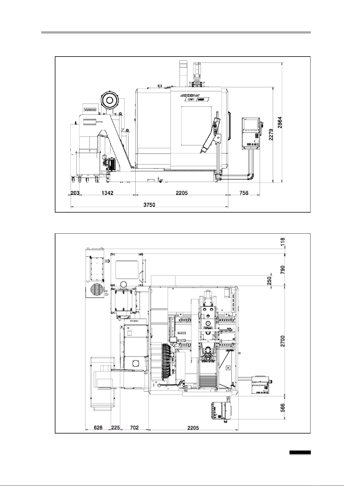
①In addition to the place of installation of the main machine body, secure sufficient
space for door opening, the chip conveyor’s length, and maintenance activities.
②Select a place that is not exposed to dust or strong corrosive gases.

5
1. Preparation Before Machine Shipping
※
Note 1) : Standard Machine Front View
※
Note 2) : Standard Machine Top View

6
1. Preparation Before Machine Shipping
※
Note 3) : Standard Machine Right View

7
1. Preparation Before Machine Shipping
1.2 Foundation Work
1) Foundation Work Period and Inspection
①Ideally, it should take at least two months from completion of the foundation to
installation of the machin.
▪The concrete will need to be cured for a period of one month or more.
②After the foundation is completed, the foundation should be checked based on the
foundation drawing. If an examination of dimensions of various parts of the foundation
pose problems, the repair must be completed before the machine arrives.
2) Machine installation foundation drawing
1) Power supply wiring to the machine must be prepared and constructed by the user
.
2) Curing period of primary concrete should be one month or more.
3)
The values indicated on the drawing are recommended values only; and, in the
case of soft ground, verification by a structural designer is required.

8
1. Preparation Before Machine Shipping
※Main Values
Machine Weight 7.5 ton
Maximum weight of workpiece 0.4 ton
Bearing of soil 5 Ton/㎡
※Tolerance
Flatness ±10mm
Pitch of Holes Single ±10mm
Accumulated ±20mm
Dimension of Holes ±10mm
※Foundation Material
Concrete Strength 240kg/㎠
Quantity 1.44㎥(3.5Ton)
※
Detailed Drawings
FL=0
Styrofoam
Concrete
Side Anchor
150
200
300
Reinforces the ground by driving files if necessary
Filing with quality rubbles and gravels and fully tamped down
Reinforce concrete with diagonally placed steel bars

9
1. Preparation Before Machine Shipping
No. Parts No. Description Mat./Specification
Q’ty Remarks
10 P88073613 Leveling Bolt S45C 6
Level
Block
20 P88100036 Hex. Nut S45C 6
30 00201-04106 Leveling Block GC250 6
40 100203-01052 Clamp; Z S45C 4
Side
Anchor
(Optional)
50 120112-01428 Clamp Bolt HIT-C M20×320 4
60 S5101101 Spring Washer ZS20 4
70 S5001101 Plane Washer ZP20 4
80 S4001132 Hex. Nut NA M20×16 4
90 850419-00065 Screw Jack SJ130 4
※
Side Anchor Parts List
10
20
30
80
60
70
40
90
50

10
1. Preparation Before Machine Shipping
1.3 Preparation Before Machine Arrival
1)
Marking the place of machine installation
①Please refer to the machine lay-out drawing and use a removable tape to mark the
exact location of machine installation.
▪Be sure to leave sufficient space for maintenance and door opening, installation
and maintenance of the chip conveyor and the coolant tank, etc.
▪Be sure to leave sufficient apace f r om pillars of the building or other machines nearby.
②After the foundation is completed, the foundation should be checked based on the
foundation drawing. If an examination of dimensions of various parts of the
foundation pose problems, the repair must be completed before the machine arrives.
2)
Preparation of the machine’s main power cable
Prepare the main power cable in advance for connection from the factory distribution
board to the machine, so that the power can be connected as soon as the machine
arrives.
▪Cable thickness : 35㎟(220V), 25㎟(380V when using a transformer)
3) Preparation for air pressure
Prepare pneumatic hose or tube in advance to be connected from the factory pneumatic
joint to the machine so that air pressure can be connected as soon as the machine
arrives.
▪
Thickness of the hose or tube : ID Ø9mm

11
2. Machine transport and checking of shipped items
2.1 Machine Transport
The
DVF5000, except for some peripherals that are separated and shipped separately, is
transported after
being assembled with the splash guard.
Since the machine is heavy and the center of gravity is
unstable, it is important to balance
the machine as a whole when it is
being moved by a crane or forklift, and to avoid bending
or
causing scratches etc. to the splash guards and various covers.
(1) Use a crane or a forklift to lift the machine and ensure proper balancing as a whole
with any method.
(2) When using the crane, be careful not to hit the wire rope or shackle on the machine
and adjust the rope length exactly so that the machine does not tilt when lifted.
1) Using a crane
①When using a crane, its lifting height must be 7m and more.
②Dedicated fixture is necessary because of interferences on respective areas when
hanging a rope.
2100mm
2700mm
2800mm
300mm
3300mm
10,000kg
Machine weight:
7,500kg

12
2. Machine transport and checking of shipped items
2) Using a forklift
When using a forklift to transport the machine, use equipment with a rated load of 10
tons or more to ensure safety.
Auxiliary rope for
supporting option
(TMG) weight

13
2. Machine transport and checking of shipped items

14
2. Machine transport and checking of shipped items
2.2 Checking of shipped items
The following units and parts are disassembled at the fa
ctory and transported to the site for
installation.
Make sure that all items have been shipped
in good condition so that no delay occurs due
to missing or damaged items.
( Oil Cooling Unit )
( Coolant Tank & Chip Conveyor )
( Chip Bucket )
( Parts for machine anchor )
( Various Manuals and Basic Tool Box )
( Various Spare Bolts )

15
2. Machine transport and checking of shipped items
( Pallet Bundle for AWC )
( AWC (Automatic Workpiece
Changer))
( Pallets for AWC that are
unfolded )
( Jig for machine feed level
measuring )

16
5. Machine Leveling
※Note) Thickness adjustment for L/M Guide Block Liner (Y-Z)
(1) Refer to the “Y-Z squareness”above to measure the exact squareness.
(2) Calculate the amount of Liner polishing by calculating the length of square
ruler and the distance between the Z-axis L/M Guide’s two Blocks.
▪Since the distance between the two L/M Blocks is 450mm, multiply the
squareness measurement by 1.5.
(3) Take out the liner after sorting the upper or lower side L/M Block and
reassemble it after adjusting it (polishing on the spot) as calculated above.
①If the ⓐpart is “+,” completely take out the 3 outer side bolts from
among the 6 fixing bolts on the upper side L/M Block and slightly
loosen the 3 inner side bolts, and then remove the Liner upwards.
② If theⓑ part is “+”, first insert a support (wood) with a length of about
400mm into the lower part, slightly apply force to the spindle head by
moving the Y-axis, fully remove the two lower bolts from among the 4
lower side L/M Block fixing bolts, slightly loosen the two upper bolts,
and then take out the liner to the bottom.
▪If the liner gets caught and cannot be removed easily, remove the liner
while moving the Y-axis in the “-” direction in the Handle Mode by
0.01mm increments.
Support (Prop)
L/M
Block
L/M
Block
Liner
Fixing Bolt
L/M Block

17
3. Machine Anchoring Operation
3.1 Machine Homing Operation
1) Marking
the machine installation site
Mark the exact installation location of the machine using a tape that can be removed
once the machine has been installed.
2) Machine Transport
After transporting the machine to the place of installation, determine the exact position of
installation and place the machine on the factory floor.
(3) Machine Positioning
①Measure the machine’s distance from the surrounding pillars, wall and machinery,
and then gradually move the machine little by little into the exact position of
installation.
②If necessary, place wooden boards on the factory floor to protect it from scratches.
Wood
board
Position
marking

18
3. Machine Anchoring Operation
3.2 Machine Anchoring Operation
1) Items to be prepared for anchoring
For the anchoring required to secure the machine on the factory floor, first prepare the
various parts and other essentials.
①Hammer Drill
②Hammer drill bit for making a hole with a diameter of 22mm and a
depth of 150mm or
more.
③Manual dispenser for injecting the chemical anchor and chemical.
④Various anchor parts shipped with the machine (Clamp Bolt, Z-Clamp, Screw Jack,
etc.) and a marker for marking the location of the anchor hole on the floor.
⑤Vacuum cleaner for removing concrete dust generated during anchor drilling and an
air gun with a long spout for cleaning the inside of the hole.
Hammer drill
22mm hammer drill bit
Chemical anchor and manual
dispenser
Various anchor parts and
Marker (pen)
Manual
dispenser for
chemical
Chemical
anchor
Clamp
Bolt
Screw
Jack
Z-Clamp
Mark
Pen
Table of contents
Other Doosan Lathe manuals
Popular Lathe manuals by other brands

Central Machinery
Central Machinery 95647 Assembly & operating instructions

Grizzly
Grizzly G0462 owner's manual

Craftsman
Craftsman 103.23880 Operating instructions and parts list

HOLZMANN MASCHINEN
HOLZMANN MASCHINEN TFM610V operating manual

King Industrial
King Industrial KC-1440ML-2 instruction manual

Axminster
Axminster AWVSL900 user manual