Jet JWL-1015 Datasheet
Assembly Instructions and Parts List
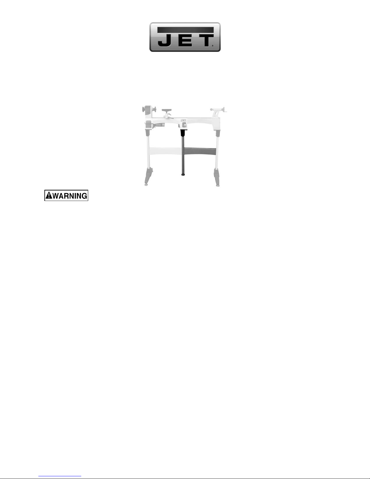
Stand Extension for JWL-1015/1015VS Lathes
Stock No. 719103
Read and understand the entire owner's manual that accompanied your JWL-1015
lathe before attempting assembly or operation of accessories.
Inspect contents for shipping damage. Report any damage or part shortages to your distributor. Do not discard
shipping materials until accessory is set up and functioning properly.
Shipping contents
1 Cross bar
1 Tube
1 Bracket
2 Socket head button screws, 5/16x1
4 Socket head button screws, 5/16x1/2
4 Lock washers, 5/16”
8 Flat washers, 5/16”
1 Leveler with nut
2 Socket head cap screws, 5/16x1
Tools required for assembly
1/4" hex key (“Allen wrench”)
9/16” (or adjustable) wrench
Assembly
(Bracketed numbers refer to index numbers in the
exploded view. Refer to documents M-719101 and
M-719102 for instructions on assembling optional
Bed Extension and Stand to lathe).
1. Install bracket [1] to tube [6] with fasteners
[2/3/4]. Tighten screws.
2. Screw leveler with nut [7/10] into bottom of
tube [6]. The leveler can be adjusted for
height, and the nut tightened up against the
tube to secure the setting.
3. Remove the right leg from your lathe.
WARNING: Use an assistant or block up the
lathe to support it during these procedures!
4. Install the leg just removed to the outer end of
the bed extension.
5. Install the middle leg beneath center of lathe
with two socket head cap screws, lock
washers, and flat washers [5/3/2], and tighten.
Adjust leveler so that it contacts the floor, and
tighten nut up against tube.
6. Secure existing cross bar to the middle leg.
7. Install new cross bar [8] between legs with four
5/16x1/2 socket head button screws [9] and
flat washers [2] and tighten.
JET
427 New Sanford Road
LaVergne, Tennessee 37086 Manual No. M-719103
Ph.: 800-274-6848 Revision A1 02/2014
www.jettools.com Copyright © 2014 JET

Specifications
Stock number................................................................................................................................................719103
Assembled dimensions.................................................................................................20.87” L x 7.48” W x 33.11”H
Net weight....................................................................................................................................................16.5 lbs
Shipping dimensions......................................................................................................30.43” L x 6.18” W x 4.76” H
Shipping weight...............................................................................................................................................19 lbs
Specifications were current at time of publication, but because of our policy of continuous improvement, JET
reserves the right to change specifications at any time and without prior notice, without incurring obligations.
# 719103 Stand extension for JWL-1015/1015VS lathes
Index No Part No Description Size Qty
1................JWL1015-201............ Upper Bracket.......................................................... ......................................1
2 ................TS-0680031 .............. Flat Washer .............................................................5/16”..............................8
3 ................TS-0720081 .............. Lock Washer............................................................5/16”..............................4
4 ................JWL1221VS-417....... Socket Head Button Screw......................................5/16”-18x1" ...................2
5 ................TS-0208061 .............. Socket Head Cap Screw..........................................5/16”-18x1”....................2
6................JWL1015-406............ Tube......................................................................... ......................................1
7 ................JWL1642-206............ Adjustable Leveler................................................... ......................................1
8 ................JWL1015-408............ Cross Bar................................................................. ......................................1
9 ................TS-0255021 .............. Socket Head Button Screw......................................5/16”-18x1/2”.................4
10 ..............TS-0561031 .............. Hex Nut....................................................................3/6”-16...........................1
To order parts or reach our service department, call 1-800-274-6848 Monday through Friday (see our website
for business hours, www.jettools.com). Having the Model Number and Serial Number of your machine available
when you call will allow us to serve you quickly and accurately.
Other manuals for JWL-1015
2
This manual suits for next models
1
Table of contents
Other Jet Lathe manuals

Jet
Jet JWL-1221VS-M User manual

Jet
Jet JWL1440-TREA Service manual

Jet
Jet JML-1014I Service manual

Jet
Jet GH-2280ZX User manual

Jet
Jet BD-920N User manual

Jet
Jet BDB-1340A User manual

Jet
Jet JWL-1221VS Datasheet

Jet
Jet Elite E-1236VS Service manual

Jet
Jet 708358 Service manual

Jet
Jet Elite EGH-1880 Service manual


