tornos MultiDeco 26/6 User manual

TORNOS SA
CH–2740 MOUTIER
http://www.tornos.ch
INSTALLATION
MULTIDECO 26/6
MULTIDECO 32/6i
300381 en
Printed in Switzerland
Copyright (c)1999–2002
∆ATTENTION !
Before handling / operating the machine,
read first the SAFETY REGULATIONS !

INSTALLATION – MULTIDECO 26/6 – MULTIDECO 32/6i
300381 en – 06/02 Chap. /2
These instructions are based on the information available at the moment of
their publication. Although the very best has been done to make them as com-
prehensive and precise as possible the instructions do not purport either to
cover all details of the hardware and software or to anticipate every con-
tingency.
TORNOS S.A. neither give any guarantee nor accept any liability for the
exactitude and the sufficiency of the information contained in this document.
The contents of the instructions remain the property of TORNOS S.A. who
reserve the right to modify, complete or correct them at any time.
Important Safety Indications
These instructions indicate a number of safety measure symbols which
appear also on the machine and are intended to protect the user, his/her
effects and the environment from injuries and damage as applicable.
Below, you will find the safety symbols, their headings and definitions. Please,
read these first before you continue.
∆Danger !
indicates a direct danger of death or serious injury.
∆Warning !
indicates an object or action which may cause death or serious
injury.
∆Attention !
indicates an object or action which may cause injury or serious
damage.
The original language of the instructions to be referred to is French. The haz-
ards of misinterpreting the instructions can be considerably reduced by
following the training courses organized and offered by TORNOS S.A.
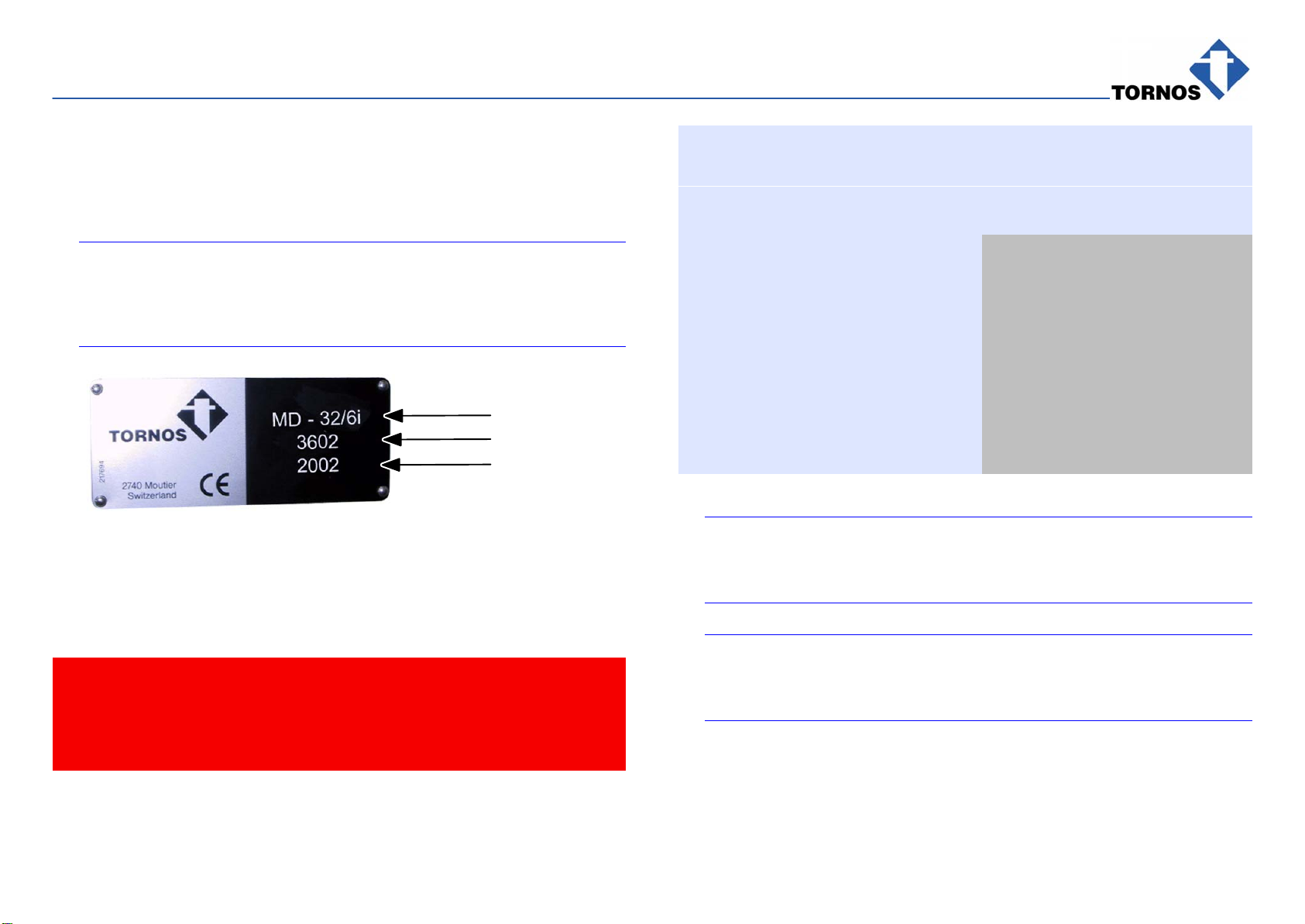
The CE-marking indicates conformity with the European standards
of safety, health, environment and protection.
∆Caution !
indicates incorrect actions or such that may cause damage.
⊗Prohibition !
indicates an action or operation prohibited because of evident or
alleged hazards.
∆Info :
gives information or comment related to safety.
⇒Note :
gives information unrelated to safety.

INSTALLATION – MULTIDECO 26/6 – MULTIDECO 32/6i
3300381 en – 06/02
TABLE OF CONTENTS
1. GENERAL 1. . . . . . . . . . . . . . . . . . . . . . . . . . . . . . . . . . . . . . . . . . . . . . . . . . . . . . . . . . . . .
1.1 IDENTIFICATION OF THE MACHINE 1. . . . . . . . . . . . . . . . . . . . . . . . . . . . . . . . . . . . . . . . . . . . . . . . .
1.2 SAFETY MEASURES & DEVICES 1. . . . . . . . . . . . . . . . . . . . . . . . . . . . . . . . . . . . . . . . . . . . . . . . . . . .
1.3 GENERAL CHARACTERISTICS 1. . . . . . . . . . . . . . . . . . . . . . . . . . . . . . . . . . . . . . . . . . . . . . . . . . . . . .
1.4 INSTALLATION OF AN IEMCA BARFEEDER FOR MULTIDECO 26/6 2. . . . . . . . . . . . . . . . . . . . .
1.5 PRESENTATION MULTIDECO 26/6 4. . . . . . . . . . . . . . . . . . . . . . . . . . . . . . . . . . . . . . . . . . . . . . . . . . .
1.6 PRESENTATION MULTIDECO 32/6I 5. . . . . . . . . . . . . . . . . . . . . . . . . . . . . . . . . . . . . . . . . . . . . . . . . .
2. UNPACKING AND CLEANING 7. . . . . . . . . . . . . . . . . . . . . . . . . . . . . . . . . . . . . . . . . .
2.1 Machine handling 7. . . . . . . . . . . . . . . . . . . . . . . . . . . . . . . . . . . . . . . . . . . . . . . . . . . . . . . . . . . . . . . . . . .
2.2 UNPACKING 8. . . . . . . . . . . . . . . . . . . . . . . . . . . . . . . . . . . . . . . . . . . . . . . . . . . . . . . . . . . . . . . . . . . . . . .
2.3 CLEANING 8. . . . . . . . . . . . . . . . . . . . . . . . . . . . . . . . . . . . . . . . . . . . . . . . . . . . . . . . . . . . . . . . . . . . . . . . .
2.3.1 Removal of rust–proofing 8. . . . . . . . . . . . . . . . . . . . . . . . . . . . . . . . . . . . . . . . . . . . . . . . . . . . . . . . . . . .
3. LOCATION/INSTALLATION 9. . . . . . . . . . . . . . . . . . . . . . . . . . . . . . . . . . . . . . . . . . . . .
3.1 FLOOR PLAN 9. . . . . . . . . . . . . . . . . . . . . . . . . . . . . . . . . . . . . . . . . . . . . . . . . . . . . . . . . . . . . . . . . . . . . .
3.1.1 Floor Plan MULTIDECO 26/6 10. . . . . . . . . . . . . . . . . . . . . . . . . . . . . . . . . . . . . . . . . . . . . . . . . . . . . . . . .
3.1.2 Floor Plan MSF–832 on MULTIDECO 26/6 11. . . . . . . . . . . . . . . . . . . . . . . . . . . . . . . . . . . . . . . . . . . . .
3.1.3 Floor Plan MULTIDECO 32/6i 12. . . . . . . . . . . . . . . . . . . . . . . . . . . . . . . . . . . . . . . . . . . . . . . . . . . . . . . . .
3.2 INSTALLATION 13. . . . . . . . . . . . . . . . . . . . . . . . . . . . . . . . . . . . . . . . . . . . . . . . . . . . . . . . . . . . . . . . . . . . .
3.2.1 Surface load 13. . . . . . . . . . . . . . . . . . . . . . . . . . . . . . . . . . . . . . . . . . . . . . . . . . . . . . . . . . . . . . . . . . . . . . . .
3.2.2 Levelling 13. . . . . . . . . . . . . . . . . . . . . . . . . . . . . . . . . . . . . . . . . . . . . . . . . . . . . . . . . . . . . . . . . . . . . . . . . . .
3.2.3 Removing transport locks 16. . . . . . . . . . . . . . . . . . . . . . . . . . . . . . . . . . . . . . . . . . . . . . . . . . . . . . . . . . . .

INSTALLATION – MULTIDECO 26/6 – MULTIDECO 32/6i
4300381 en – 06/02
3.3 MOVING THE MACHINE 17. . . . . . . . . . . . . . . . . . . . . . . . . . . . . . . . . . . . . . . . . . . . . . . . . . . . . . . . . . . .
3.3.1 Mechanical locking of lathe mobile units 17. . . . . . . . . . . . . . . . . . . . . . . . . . . . . . . . . . . . . . . . . . . . . . .
3.4 ELECTRIC INSTALLATION MULTIDECO 26/6 18. . . . . . . . . . . . . . . . . . . . . . . . . . . . . . . . . . . . . . . . . .
3.4.1 Installation characteristics 20. . . . . . . . . . . . . . . . . . . . . . . . . . . . . . . . . . . . . . . . . . . . . . . . . . . . . . . . . . . .
3.4.2 Electric Connection to 200V – 240VAC Mains 21. . . . . . . . . . . . . . . . . . . . . . . . . . . . . . . . . . . . . . . . . .
3.4.3 Electric Connection to 380V – 480VAC Mains 23. . . . . . . . . . . . . . . . . . . . . . . . . . . . . . . . . . . . . . . . . .
3.4.4 Electric connection to 500VAC mains 25. . . . . . . . . . . . . . . . . . . . . . . . . . . . . . . . . . . . . . . . . . . . . . . . . .
3.4.5 Connection of various machine peripherals 26. . . . . . . . . . . . . . . . . . . . . . . . . . . . . . . . . . . . . . . . . . . . .
3.5 ELECTRIC INSTALLATION MULTIDECO 32/6I 27. . . . . . . . . . . . . . . . . . . . . . . . . . . . . . . . . . . . . . . . .
3.5.1 Installation characteristics 28. . . . . . . . . . . . . . . . . . . . . . . . . . . . . . . . . . . . . . . . . . . . . . . . . . . . . . . . . . . .
3.5.2 Connection of various machine peripherals 28. . . . . . . . . . . . . . . . . . . . . . . . . . . . . . . . . . . . . . . . . . . . .
3.5.3 Connection and inspection procedure 30. . . . . . . . . . . . . . . . . . . . . . . . . . . . . . . . . . . . . . . . . . . . . . . . .
3.5.4 Electrical connection depending on mains type 31. . . . . . . . . . . . . . . . . . . . . . . . . . . . . . . . . . . . . . . . .
3.6 PNEUMATICS INSTALLATION 32. . . . . . . . . . . . . . . . . . . . . . . . . . . . . . . . . . . . . . . . . . . . . . . . . . . . . . .
3.6.1 Required air quality 32. . . . . . . . . . . . . . . . . . . . . . . . . . . . . . . . . . . . . . . . . . . . . . . . . . . . . . . . . . . . . . . . . .

INSTALLATION – MULTIDECO 26/6 – MULTIDECO 32/6i
300381 en – 06/02 Chap. 1.3 /1
1. GENERAL
1.1 IDENTIFICATION OF THE MACHINE
⇒Note:
Placed on the right side of the machine, this plate indicates primarily the
machine version number, to be quoted when contacting TORNOS ser-
vices.
Type
Series
Year
1.2 SAFETY MEASURES & DEVICES
These are described in the Instructions 300460 “SAFETY REGULATIONS”.
∆ Caution!
Failure to comply with the safety regulations
may cause serious accidents.
1.3 GENERAL CHARACTERISTICS
Data Characteristics
MULTIDECO
26/6 MULTIDECO
32/6i
Length 6035 mm 8300 mm
Width 1600 mm 1720 mm
Height (without indicator lamp) 1950 mm 2158 mm
Weight of machine equipped with
switch cabinet 13 axes: 8000kg
17 axes: 8500kg
19 axes: 9000kg
8300kg
Load per surface unit of floor approximately
12
daN/cm2
approximately
12 daN/cm2
⇒Note :
For more details, consult your operating instructions entitled :
MACHINE EQUIPMENT.
⇒Note :
For more details, consult your operating instructions entitled :
OPERATION & MAINTENANCE.
DIMENSIONS
– See chapter entitled ”Location/Installation”

INSTALLATION – MULTIDECO 26/6 – MULTIDECO 32/6i
300381 en – 06/02 Chap. 1.4 /2
1.4 INSTALLATION OF AN IEMCA barfeeder for MULTIDECO 26/6
∆Attention !
For impeccable operation of the BARFEEDER–LATHE assembly
TORNOS have issued instructions with the characteristics & functions
required for the feeder–lathe interface. The instructions are entitled :
INTERFACE SPECIFICATIONS FOR STOCK TUBE OR BARFEEDER
These specifications must be strictly complied with to avoid malfunction-
ing of the bar feeding system, which might be imputed to the lathe.
TORNOS declines any liability whatsoever, should a damage or acci-
dent be imputed to a tube / feeder which do not conform to the said
specifications &/or standards in force.
BARFEEDER INSTALLATION
Action Notes
– Remove feed mechanism 1 and
stock feed tube 2. Fig. 112
– Turn dia. 38 in bronze rings. Fig. 111
111

INSTALLATION – MULTIDECO 26/6 – MULTIDECO 32/6i
300381 en – 06/02 Chap. 1.4 /3
112
2
1
>>>

INSTALLATION – MULTIDECO 26/6 – MULTIDECO 32/6i
300381 en – 06/02 Chap. 1.5 /4
1.5 PRESENTATION MULTIDECO 26/6
6
310
1
2
8
9
7
5
3
1
11
1. See–thru door for machining range
Ident. no. 217439
2. See–thru door for chuck and feed range
Ident. no. 217441
3. See–thru door for spindle housing
Ident. no. 217440
5. See–thru door for manual chucking range
Ident. no. 217441
6. NC Keyboard
7. Switch cabinet
8. Control panel
9. NC screen
10. See–thru door with opening on part output side
Ident. no. 217442
11. See–thru door for access to gear housing
Ident. no. 217441
Item nos. 1, 2, 3, 5, 10, 11: See–thru door alone with glued guiding “U” profile.

INSTALLATION – MULTIDECO 26/6 – MULTIDECO 32/6i
300381 en – 06/02 Chap. 1.6 /5
1.6 PRESENTATION MULTIDECO 32/6i
8
7
6
5
4123 109
1. See–thru door for machining range
Ident. no. 217439
2. See–thru door for chuck and feed range
Ident. no. 217441
3. See–thru door for spindle housing
Ident. no. 217440
5. See–thru door for manual chucking range
Ident. no. 217441
6. NC Keyboard
7. Switch cabinet
8. Control panel
9. NC screen
10. See–thru door with opening on part output side
Ident. no. 217442
11. See–thru door for access to gear housing
Ident. no. 217441
Item nos. 1, 2, 3, 5, 10, 11: See–thru door alone with glued guiding “U” profile.

INSTALLATION – MULTIDECO 26/6 – MULTIDECO 32/6i
300381 en – 06/02 Chap. 1.6 /6
>>>

INSTALLATION – MULTIDECO 26/6 – MULTIDECO 32/6i
300381 en – 06/02 Chap. 2.1 /1
2. UNPACKING AND CLEANING
2.1 Machine handling
⇒Note
Lifting and moving of the machine must only be carried out using the
appropriate equipment supplied with the machine, which must be
located only in the places indicated in transport documents 300379 or
300369.
Lift the machine together with its switch cabinet by means of a pulley block
& beam or mechanical/hydraulic jacks.
With a lifting pulley block & beam:
Put four lifting bars 3, supplied with the machine, into the openings in the
base. Screw in 8 fixing screws 4 merely to keep the lifting bars from acciden-
tally slipping out of the base.
∆Attention!
Do not tighten the bolts. Leave 0.5–1.5 mm play between the screw
heads and the lifting bar flange.
Slip 2 ties 5 on 2 bars 3 and into axes 18 of the switch cabinet. Screw tie nuts
9 to bring the switch cabinet close to the machine and support it.
Hitch lifting slings 6 round all bars 3 and at lifting beam 7. Put wooden wedges
between the slings and enclosure 8 to protect the latter. Fit the horizontal
door–handles in place. Lift the machine slowly; 2 beams inside the base also
support the switch cabinet.
With a mechanical / hydraulic jack:
Put 4 jacks under lifting bars 3. Lift the machine together with the switch cabi-
net. Slide 2 or 3 roller flats underneath to facilitate transport.
⇒Note.
The lifting and handling equipment (function 8910 of technical descrip-
tion 300429 for MULTIDECO 26/6 or 300519 for MULTIDECO 32/6) may
be returned to TORNOS S.A. after use.
Replace the coolant tank, the conveyor, the MAYFRAN tank, reconnect the
tubes.
Stabilise back plate 27 by fixing it with the 2 M24 screws of the coolant tank.
Fit the barguide and level it by means of the 3 levelling elements of its rear
support.
∆Attention!
The machine must not be operated with open doors and guards.
Before switching the machine on and starting up, make sure that all
doors, access doors and other guards are properly closed.
The switch cabinet is attached to the frame with 2 M16 bolts, situated down
in the cabinet and accessible through its door on the side of Main Switch QS0.

INSTALLATION – MULTIDECO 26/6 – MULTIDECO 32/6i
300381 en – 06/02 Chap. 2.3.1 /2
2.2 UNPACKING
Pull out nails from the cover and then from the walls of the case. Remove the
vacuum–packing plastic.
Remove the wooden wedges and ropes that hold various items.
⇒Note:
Refer to the transport document
– 300379 for MULTIDECO 26/6 or
– 300369 for MULTIDECO 32/6i
supplied with all the machine documentation.
∆Caution!
Unlocking must not be performed until the machine has been set in
position.
2.3 CLEANING
2.3.1 Removal of rust–proofing
⇒Note:
The rust inhibitor applied depends on the particular destination.
∆Attention!
Cleaning must only be performed in well–ventilated areas
(inhalation of toxic vapours).
Action Notes
Clean carefully all the parts cov-
ered with anti–rust coating using
cloths soaked in benzine or paraf-
fin
∆Caution!
Cause no damage or misadjust-
ment.
∆Avoid using compressed air and
products which may damage
synthetic materials.

INSTALLATION – MULTIDECO 26/6 – MULTIDECO 32/6i
300381 en – 06/02 Chap. 3.1 /1
3. LOCATION/INSTALLATION
3.1 FLOOR PLAN
⇒Note:
The dimensions relate to the standard configuration with optional (addi-
tional) tank and cooler. Be sure to take into account for your particular
floor plan the dimensions of other options added to the machine, such
as barfeeder, mist & smoke control unit, etc.
>>>

INSTALLATION – MULTIDECO 26/6 – MULTIDECO 32/6i
300381 en – 06/02 Chap. 3.1.1 /2
3.1.1 Floor Plan MULTIDECO 26/6
199260f1
(dimensions with MSF–832 barfeeders for 4 metre bars)

INSTALLATION – MULTIDECO 26/6 – MULTIDECO 32/6i
300381 en – 06/02 Chap. 3.1.2 /3
3.1.2 Floor Plan MSF–832 on MULTIDECO 26/6
(9300)
199413
(dimensions with MSF–832 for 4 metre bars)

INSTALLATION – MULTIDECO 26/6 – MULTIDECO 32/6i
300381 en – 06/02 Chap. 3.1.3 /4
3.1.3 Floor Plan MULTIDECO 32/6i
199264f1
(dimensions with MSF–832 barfeeders for 4 metre bars)

INSTALLATION – MULTIDECO 26/6 – MULTIDECO 32/6i
300381 en – 06/02 Chap. 3.2.2 /5
3.2 INSTALLATION
3.2.1 Surface load
∆Caution!
Take account of the admissible loading of the floor depending on the
machine equipment to be installed
– approximately 12 daN/cm2.
P = Floor loading per levelling pad.
P = 2500 kg
P = 5000 kg
250
=
250
=
3.2.2 Levelling
∆Caution!
To ensure correct functioning of the machine under the best possible
conditions, the levelling procedure described hereafter must be strictly
complied with.
The machine must be installed on a hard, stable, vibration–free floor. If this
is not available, cast a concrete bedding.
While the machine is lifted, remove 4 (transport) plates 1, insert instead 2 bolts
10 of levelling elements 15 in the holes and keep screwing nuts 11 until level-
ling elements 15 rest against the bed plates, switch cabinet side.
Put the base definitively down on the floor directly or in a flat sump, ensuring
that the third support element is set in place (250 x 250 mm, see Fig. oppo-
site).
⇒Note:
The switch cabinet rollers must touch the floor. Ties 5 are then relieved
from carrying the weight of the cabinet.
Perform levelling carefully by turning the screws 17 of the levelling elements
15.
Use a precision spirit level: 0.020 mm/1000 mm, positioned on the base in
front of the control frame (Figs. 302 to 305).

INSTALLATION – MULTIDECO 26/6 – MULTIDECO 32/6i
300381 en – 06/02 Chap. 3.2.2 /6
∆Caution!
Once the machine is in position, remove the foam rubber protection 6
from the machine base near the coolant tank. (Figs. 301 & 302)
53
2
301
6
5 (2x 240950) 3
4
(217147)
1
302
2
6Positioning of the level
1. The space nos. 2 and 3 (Figs. 301 & 302) must be relieved of any weight,
so that the machine base is borne only by element nos. 1, 4 and 5.

INSTALLATION – MULTIDECO 26/6 – MULTIDECO 32/6i
300381 en – 06/02 Chap. 3.2.2 /7
303
2. With the level in diagonal position (Fig. 303), effect horizontal levelling by
means of levelling element nos. 1 and 4.
304
3. Place the level parallel to the longitudinal axis of the machine (Fig. 304)
and if necessary adjust the setting by means of levelling element no. 1.

INSTALLATION – MULTIDECO 26/6 – MULTIDECO 32/6i
300381 en – 06/02 Chap. 3.2.3 /8
305
4. Place the level perpendicularly to machine axis (Fig. 305) and check if
transverse axis of the base is horizontal. If necessary, adjust the setting
by means of levelling element nos. 1 and 4 by repeating the directional
checks under points 2 and 3.
3.2.3 Removing transport locks
Action Notes
Remove the wooden wedges and
ropes that hold various items in
place.
Oil tank, chip pan, manipulator,
hatches.
Remove mechanical locking
devices Locking device
Put away the locking pieces for
possible future use.
∆Caution!
Unlocking must not be performed until the machine has been set in
position.
This manual suits for next models
1
Table of contents
Other tornos Lathe manuals