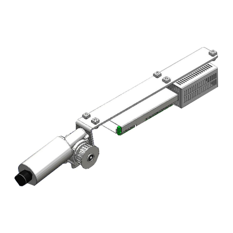
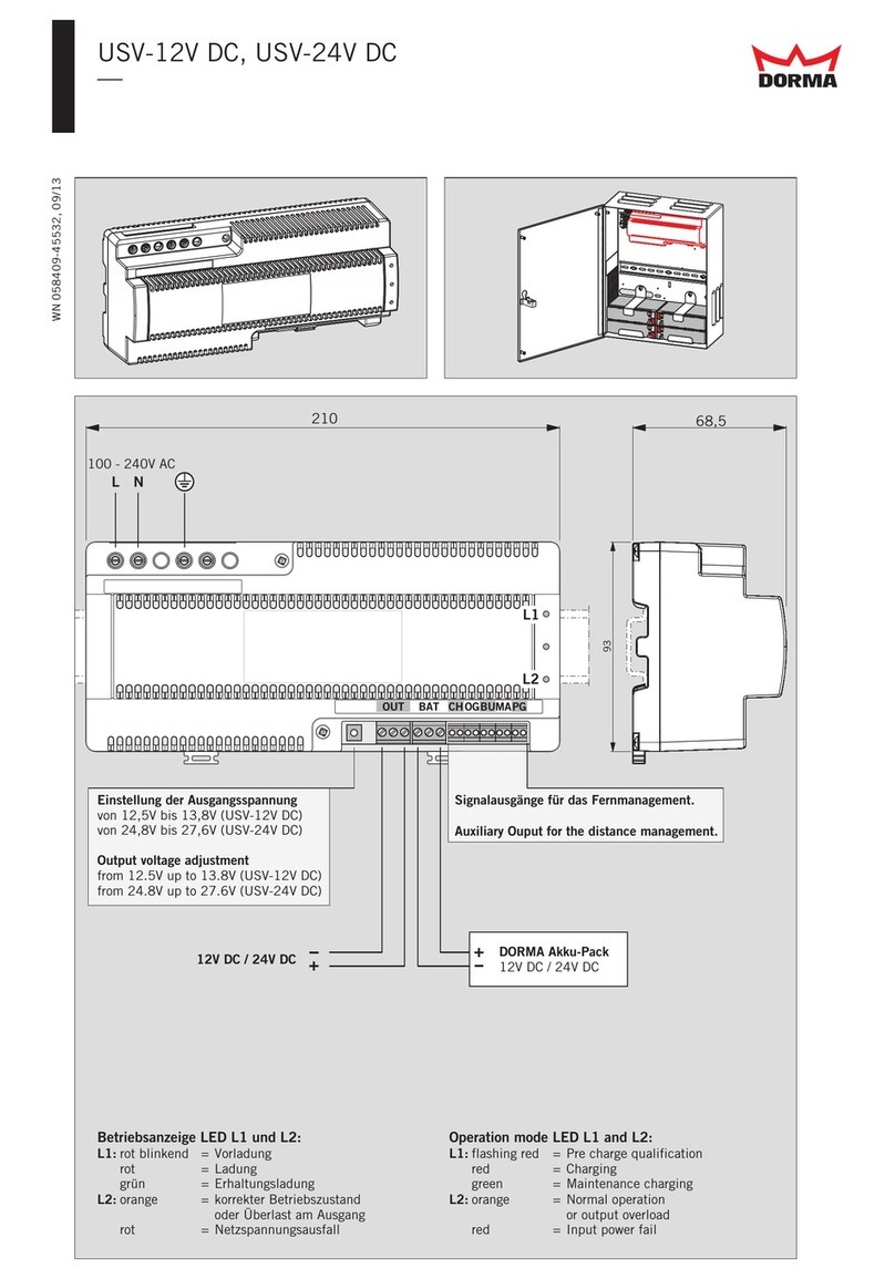
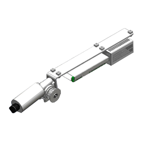
Dorma ESA II Operating instructions

Commissioning, maintenance
and troubleshooting instructions
ESA II
—
Controller

TABLE OF CONTENTS
—
ESA II controller commissioning, maintenance and troubleshooting
instructions
1General information 4
2Product overview 4
3Safety 4
4Technical data 5
5Door signage – sliding doors 6-7
6Product description 8
7ESA II system block diagram 9
8ESA II controller and interface to ESA II expansion module 10
9ESA II electrical interface diagram 11
10 ESA II expansion module 12
11 ESA II user interface
AOverview 13
BDisplay operation 13
CAccessing error codes 14
DAccessing parameters 15
EParameter settings – codes 16
12 Operating instructions – program switch panel 17
13 Operating instructions – setting partial open door width 17
14 115 VAC power connection at header 18-19
15 ITS door closer and deadstop adjustment for breakout 20-21
16 Installation requirements prior to commissioning 22
17 First commissioning 23
18 Perform learning cycle 24
19 Set door parameters 25-26
20 Test of door opening cycle 26
21 Reset controller to factory settings 27
22 ESA II expansion module – DCW address 48
ASecuring secondary closing edges 28
BPanic closing function 29
CDoor status contact 30
23 ESA II expansion module – DCW address 49
AAirlock function 30-31

TABLE OF CONTENTS
—
ESA II controller commissioning, maintenance and troubleshooting
instructions
24 Functional test
AActivation, presence and safety beam sensors 32
BDoor or door and sidelight breakout 33
CMonitoring of opening and closing forces – obstruction 34
DAutolock assembly 35
EAutolock – fail safe assembly 36
FNight-bank contact (optional) 37
GBackup battery functional overview 38
HBackup battery – no battery 39
IBackup battery – emergency closing 40
JBackup battery – emergency opening 41
KBackup battery – emergency mode 41
25 Wiring Diagrams
A Program switch panel
42
BAutolock assembly 43
CAutolock – fail safe assembly 43
DSidelight breakout switch – single door 44
ESidelight breakout switch – double doors 44
FBreakout beam with BEA Microcell One 44
Blank page 45
G Activation / safety sensors –BEA IXIO-DT1
46
Blank page
47
I Activation / safety sensors –
Optex X Zone T and i oneX T
48
Blank page
49
26 Maintenance 50-51
27 Troubleshooting 52-53
Appendix
AANSI BHMA A156.10 sensors, sliding doors 54-55
BDorma Handheld parameters 56-61
C BEA Microswitch One installation and troubleshooting
62
Blank page
63

ESA II CONTROLLER COMMISSIONING, MAINTENANCE AND
TROUBLESHOOTING INSTRUCTIONS
—
DORMA USA, Inc. 1 Dorma Drive, Drawer AC T: 717-336-3881 Subject to change without notice
DL2842-010 05/2017 Reamstown, PA 17567 F: 717-336-2106
4
1 General information
This manual provides information on ESA II Controller wiring,
commissioning, maintenance, and troubleshooting.
This document must be kept in a secure place. It must be
accessible for reference as required.
If system should be transferred to another facility, insure that
this document is transferred as well.
Installation manuals are available for review,
download, or printing on the Dorma.com website.
Symbols used in these instructions
WARNING
This symbol warns of hazards which
could result in personal injury or threat
to health.
REMARK A remark draws attention to important
information in this document.
NOTE
A note clarifies instructions or other
information presented in this
document.
Dimensions
Unless otherwise specified, all dimensions are given
in both inches (") and millimeters [mm].
3 Safety
This document contains important instructions for installation
commissioning, and safe operation of the ESA II controller.
Review these instructions thorougly prior to installation, and
follow them carefully during installation and commissioning,
as well as during maintenance and troubleshooting.
Damage to equipment, or incorrect equipment
operation, may result from an incorrect installation
or commissioning of the ESA II system.
Hazard of electric shock! By use of control
elements, settings,
or procedures not
documented in this
manual!
Hazard to mechanical
processes!
Signage
Reference Section 5 – Door signage.
Proper signs and labels shall be applied and maintained on the
door per the following ANSI / BHMA standards:
ANSI/BHMA A156.10-2011: Standard for power operated
pedestrian doors, paragraph 11, signage.
Maintenance: If signs have been removed, or
cannot be read, request that signs be replaced by
contacting local Dorma company.
2 Product overview
Intended use
The ESA drive motor assembly core components consist of
a gearmotor with encoder, ESA II controller, and DC power
suppply. This assembly controls door motion of the ESA series
of sliding doors.
ESA drive motor assembly
Drive motor assembly
ESA header assembly
Building codes and standards
ESA II controller wiring installation: observe applicable
national and local building codes.
ESA II controller commissioning: observe following standard
and any applicable national or local standards:
ANSI/BHMA A156.10-2011: Standard for power
operated pedestrian doors
Safety
Electric shock hazard while working on ESA II drive
motor assembly and incoming 115 VAC power!
Work on electrical equipment and wiring installation
must be performed only by qualified electricians!
Metallic doors must be grounded per national and
local codes.
DC power
supply
ESA II
controller
Motor gearbox
Encoder

ESA II CONTROLLER COMMISSIONING, MAINTENANCE AND
TROUBLESHOOTING INSTRUCTIONS
—
DORMA USA, Inc. 1 Dorma Drive, Drawer AC T: 717-336-3881 Subject to change without notice
DL2842-010 05/2017 Reamstown, PA 17567 F: 717-336-2106
5
Power supply
AC power 120 VAC ± 10%, 50/60 Hz
Fuse 6.6 amp, not replaceable
Power supply
external accessories 27 VDC, 2 amperes
Power consumption, max. 250 watt
Driving parameters
Parameter and description Units Default Min. Max.
Maximum opening speed inches/sec. 20* 422
cm/sec. 51* 10 56
Maximum closing speed inches/sec. 12* 412
cm/sec. 30* 10 30
[Opening accel.] Maximum distance for acceleration to opening speed. n/a 719
[Closing accel.] Maximum distance for acceleration to closing speed. n/a 719
[Decel. ramp open] Maximum deceleration ramp at end of door opening cycle. n/a 419
[Decel. ramp close] Maximum deceleration ramp at end of door closing cycle. n/a 419
[Creep speed open] Maximum creep speed at end of door opening cycle. inches/sec. 214
cm/sec. 52.5 10
[Creep speed close] Maximum creep speed at end of door closing cycle. inches/sec. 214
cm/sec. 52.5 9
[Creep dist. open] Maximum distance of creep speed cycle at end of door
opening cycle.
inches 1012
cm 2.5 030
[Creep dist. close] Maximum distance of creep speed cycle at end of door
closing cycle.
inches 2012
cm 5030
Hold open time – Display value * 0.1 seconds 15* 15 1800
Hold open time, Night/bank – Display value * 0.1 seconds 15* 15 600
[Delayed opening] Delayed opening after Night / Bank pulse was triggered. seconds 0010
[Partial Open] Partial opening width after learning cycle.
Display value * 0.1 inches 315 10 3150
[Force limit open] Force limitation during door opening cycle. pounds 30* 11 70
Newtons 133* 49 311
[Force limit close] Force limitation during door closing cycle. pounds 20* 11 70
Newtons 89* 49 311
[Latching action] Required force to keep door closed. n/a 609
* Default may be modified during door learning cycle.
4 Technical data
Door functions
Close
Automatic
Permanent open
Partial open
Exit
Parameters in [brackets] accessible only
by Dorma Handheld

ESA II CONTROLLER COMMISSIONING, MAINTENANCE AND
TROUBLESHOOTING INSTRUCTIONS
—
DORMA USA, Inc. 1 Dorma Drive, Drawer AC T: 717-336-3881 Subject to change without notice
DL2842-010 05/2017 Reamstown, PA 17567 F: 717-336-2106
6
ESA sliding doors are supplied with door sign decals to alert
and instruct pedestrian traffic in operation and function of door.
Method of activation determines combination of decals required.
Not all decals will be used in every application.
Safety signs are specified in ANSI A156.10, American National
Standard for power operated pedestrian doors, paragraph 11.
All swinging, sliding and folding doors
1. AUTOMATIC CAUTION DOOR sign – all sliding doors shall
be equipped with signage visible from both sides of door
reading "AUTOMATIC CAUTION DOOR", with letters a
minimum of 1/2" [12.7 mm] high.
Sliding doors
2. IN EMERGENCY PUSH TO OPEN sign – install with sliding
doors with breakout doors and shall be applied to side
appropriate for egress. Signs shall have red backgrounds
with contrasting letters a minimum of 1" high. Signs shall
read horizontally and be located next to lock stile on a
centerline 36" minimum and 60" maximum from the floor.
3. STAND CLEAR sign – sliding doors that slide alongside
an adjacent sidelight or wall shall be equipped with a
sign that instructs users to stand clear of the sliding door
travel path. The letters shall be a minimum of 1" high
on contrasting background and located from 36" to 60"
from floor.
4. ACTIVATE SWITCH TO OPERATE sign – Door shall also
have ACTIVATE SWITCH TO OPERATE sign on side of
door with knowing act switch. Each sign in 1/2" high
minimum letters.
AAADM safety information label
6. This AAADM label outlines safety checks that should be
performed daily on automatic sliding door. Place label in
a protected, visible location on door frame, near operator
power switch if possible.
AAADM annual compliance inspection label
7. Place additional labels directly over "Annual Compliance
Inspection" section of Safety Information label.
This label is only placed on doors that comply with
ANSI/BHMA A156.10 standard and pass inspection.
2
3
6
1
SAFETY INFORMATION
Automatic Sliding Doors
1. Walk toward the door at a
normal pace. The door
should open when you are
about 4 feet from the door.
2. Stand motionless on
threshold for at least 10
seconds. The door should
not close.
3. Move clear of the area. The
door should remain open for
at least 1.5 seconds and
should close slowly and
smoothly.
4. Repeat steps 1 through 3
from other direction if door
is used for two way traffic.
5. Inspect the floor area. It
should be clean with no
loose parts that might cause
user to trip or fall. Keep
traffic path clear.
6. Inspect door's overall
condition. The appropriate
signage should be present.
7. Have door inspected by an
AAADM certified inspector
at least annually.
AAADM
American Association of Automatic
Door Manufacturers
ANNUAL COMPLIANCE
INSPECTION
INSPECT FOR AND
COMPLIES WITH ANSI
A156.10 ON:
DATE:______________
by AAADM Certified
Inspector
Number:___________
AAADM-2495
These minimum safety checks,
in addition to those in the
Owner’s Manual, should be
made each day and after any
loss of electrical power.
DO NOT USE DOOR if it fails
any of these safety checks of if it
malfunctions in any way. Call
a qualified automatic door
service company to have door
repaired or serviced.
See Owner’s manual or
instructions for details on
each of these and other
safety items. If you need
a copy of the manual,
contact the manufacturer.
5 Door signage – sliding doors
ANNUAL COMPLIANCE
INSPECTION
INSPECT FOR AND
COMPLIES WITH ANSI
A156.10 ON:
DATE: _____________
by AAADM Certified
Inspector
Number: ____________
7
4

ESA II CONTROLLER COMMISSIONING, MAINTENANCE AND
TROUBLESHOOTING INSTRUCTIONS
—
DORMA USA, Inc. 1 Dorma Drive, Drawer AC T: 717-336-3881 Subject to change without notice
DL2842-010 05/2017 Reamstown, PA 17567 F: 717-336-2106
7
OSX SX O
60” max.
36” min.
BREAKOUT
58” ± 5”
OSX SX O
INTERIOR
EXTERIOR
BREAKOUT
BREAKOUT
60” max.
36” min.
Automatic bi-part slide door with signage for two-way traffic control
Automatic single slide door with signage for two-way traffic control
58” ± 5”
INTERIOR
EXTERIOR
INTERIOREXTERIOR
1
7
1
2
2
3
33
6
ANNUALCOMPLIANCE
INSPECTION
INSPECTFORAND
COMPLIESWITHANSI
A156.19ON
DATE:_____________
byAAADMCertified
Inspector
Number:__________
ANNUALCOMPLIANCE
INSPECTION
INSPECTFORAND
COMPLIESWITHANSI
A156.19ON
DATE:_____________
byAAADMCertified
Inspector
Number:__________
7
6
4
4
1
1
2
4
4
SX Breakaway sliding door
O Fixed sidelight

ESA II CONTROLLER COMMISSIONING, MAINTENANCE AND
TROUBLESHOOTING INSTRUCTIONS
—
DORMA USA, Inc. 1 Dorma Drive, Drawer AC T: 717-336-3881 Subject to change without notice
DL2842-010 05/2017 Reamstown, PA 17567 F: 717-336-2106
8
L
BK
1
5
BN
WH
YE
GN
BN
BL
WH
BK
YE RD
DC Power supply
35 VDC
120 VAC
50/60 Hz
Motor gearbox
Incremental encoder
N
ESA II controller
26
27
28
29
30
31
32
33
34
35
36
37
38
+ 35VDC
Gnd
Inhibit
Motor cable
Encoder cable
6 Product description
ESA drive motor assembly
1. DC power supply
Operates from external 115 VAC, 50/60 Hz supply.
Supplies +35VDC to ESA II controller.
6.6 ampere internal fuse (not replaceable)
2. ESA II controller
Controls ESA sliding door motion through motor gearbox
with encoder feedback.
Provides interfaces to sensors and activators.
Supplies + 27 VDC for external devices.
Provides interface to separate optional function module
with digital inputs and isolated contact outputs.
Operator interface for setup, status, and parameter
adjustments.
3. Motor gearbox with encoder feedback.
Provides ESA sliding door motion.
ESA drive motor assembly
DC power
supply
ESA II
controller
Motor gearbox
Encoder

ESA II CONTROLLER COMMISSIONING, MAINTENANCE AND
TROUBLESHOOTING INSTRUCTIONS
—
DORMA USA, Inc. 1 Dorma Drive, Drawer AC T: 717-336-3881 Subject to change without notice
DL2842-010 05/2017 Reamstown, PA 17567 F: 717-336-2106
9
7 ESA II system block diagram
35V switching
power supply
Emergency OFF
switch
Activation
external
Service DCW
interface
Battery
backup
Electric
lock
Night-/Bank-open
Program
switches
DCW
interface
DC signal
inputs
Outputs
Isolated relay
contacts
COM 1
Programming
interface
DIP switch
ESA II
Interconnection
LON- adapter
Motor gearbox
Encoder
10
9
8
7
6
5
4
3
2
1
11
12
13
14
15
16
17
18
19
20
21
22
23
24
25
26
27
28
29
30
31
32
33
34
35
36
37
38
10
9
8
7
6
5
4
3
2
11
12
13
1
14
15
16
17
18
19
21
20
1
2ESA II
Expansion
module
39
40
41
42
43
44
Breakout sensor
Activation
internal Presence 2 Presence 1
Dorma Handheld
RJ45 socket
+
+
ESA II expansion module interface cable

ESA II CONTROLLER COMMISSIONING, MAINTENANCE AND
TROUBLESHOOTING INSTRUCTIONS
—
DORMA USA, Inc. 1 Dorma Drive, Drawer AC T: 717-336-3881 Subject to change without notice
DL2842-010 05/2017 Reamstown, PA 17567 F: 717-336-2106
10
Service
Interface
8 ESA II controller and interface to ESA II expansion module
Service
Interface
ESA II Expansion module interconnect cable DX2889-002
ESA II expansion module to ESA II controller interface cable
ESA II controller
Terminal blocks
Wire sizes
Solid and stranded:
26 - 16 AWG [0.14 -1.5 mm2]
Stranded wire with ferrrule:
24 - 18 AWG [0.25 -1.0 mm2]
Wire strip length: 1/4" [7]
Screw size: M2
Screw head diameter: 5/32" [3.8]
Screw torque: 2.2 in-lb [0.25 Nm]
Expansion module cable
Power must be removed
from ESA II controller
before connecting or
removing cable!
Key
Key Key
Key
+ Brn + Brn
(+) Brn
Grn
Yel
Wht
(+) Brn
Grn
Wht
Yel
59” [1500] +/- 3/4”

ESA II CONTROLLER COMMISSIONING, MAINTENANCE AND
TROUBLESHOOTING INSTRUCTIONS
—
DORMA USA, Inc. 1 Dorma Drive, Drawer AC T: 717-336-3881 Subject to change without notice
DL2842-010 05/2017 Reamstown, PA 17567 F: 717-336-2106
11
Night / Bank
Close
Automatic
Exit only
Partial open
Permanent open
Gnd
Gnd
Program
switches
Brn
Grn
Red
Wht
Blk
+27 VDC
Lock
Unlock
Status ___
Gnd
1
2
3
4
5
6
7
8
9
10
11
12
13
14
15
16
17
18
19
20
21
22
23
24
25
26
27
28
29
30
31
32
33
34
35
36
37
38
39
40
41
42
43
44
+27 VDC
Gnd
Signal
+27 VDC
Gnd
Signal
+27 VDC
+27 VDC
Gnd
+27 VDC
+27 VDC
Gnd
+27 VDC Service
Open source 1.5A
Breakout-cutoff
switch (optional)
Jumper if not used
+35 VDC DC power supply
Red
Gnd Black
Inhibit Yellow
+27 VDC
Gnd
Red
Black
+ 27 VDC
Signal A
Signal B
Gnd
DCW interface
Brown
White
Motor
Motor encoder
+ 27 VDC
Signal B
Signal A
Gnd DCW interface
to ES 200
Encoder
M
45
46
47
48
Locking
FST - Interface
Dorma
Handheld
Interconnection
LON - adapter
Encoder
Motor
+35 VDC Power supply
DCW
DCW
Battery
backup
136
14 33
39
42
ESA II
45
48
Battery backup
Receiver 2 Presence 2
(LED 2)
Presence 1
(LED 1)
Transmitter 2
Receiver 1
Transmitter 1
Activation
external
Activation
internal
9 ESA II electrical interface diagram
Bottom view
AUTO CLOSE
OFF
OFF
OPEN
EXIT ONLY
ON
ON
PARTIAL OPEN
Red Exit
White Partial Open
Brown Permanent Open
Green Automatic
Blk Gnd
Program switches
4 3/4” [120 mm]
Red – +35VDC
Black – Gnd
Yellow – Inhibit
3 pole plug
DC power supply
6.6A Fuse – not replaceable
DC power
supply
ESA II
controller
Motor gearbox
Encoder
ESA drive motor assembly

ESA II CONTROLLER COMMISSIONING, MAINTENANCE AND
TROUBLESHOOTING INSTRUCTIONS
—
DORMA USA, Inc. 1 Dorma Drive, Drawer AC T: 717-336-3881 Subject to change without notice
DL2842-010 05/2017 Reamstown, PA 17567 F: 717-336-2106
12
GND
GND
OUT 2
OUT 3
OUT 4
OUT 1
NC
C
NO
C
NO
NC
C
NO
NC
C
NO
DC inputs
Outputs
Maximum
switching
current
1A @ 30VDC
0.5A @125VAC
0.3A @ 60VDC
IN 1
IN 2
IN 3
+27VDC
IN
+27VDC
IN
IN -
IN +
1
2
3
4
5
6
9
10
7
8
11
12
13
14
15
16
17
18
19
DCW Interface to ESA II
GND
+27VDC
Signal B
Signal A
DCW address 48 DCW address 49
DIP switch
22
23
24
25
Cable Connections of a DCW device
Check wire terminations before applying power.
Interchanged wires (+27 VDC to signal A or
B terminals, or a missing GND connection)
may permanently damage all connected DCW
12
ON
12
ON
12
ON
DIP switch
Power MUST be removed from ESA II controller
before changing DIP switch settings!
devices!
10 ESA II Expansion module
ESA II expansion
module DX2889
ESA II
controller
ESA200 header assembly
Motor
gearbox
Mount ESA II expansion module against back wall of header
approximately 12" [305] from end of motor gearbox.
Power MUST be removed from ESA II controller
before installing module and connecting cable!
Use 3M™ industrial VELCROW® to secure module to header.

ESA II CONTROLLER COMMISSIONING, MAINTENANCE AND
TROUBLESHOOTING INSTRUCTIONS
—
DORMA USA, Inc. 1 Dorma Drive, Drawer AC T: 717-336-3881 Subject to change without notice
DL2842-010 05/2017 Reamstown, PA 17567 F: 717-336-2106
13
LED 2 Threshold presence sensor input
LED 1 Threshold presence sensor input
7 segment display Information display: status, error codes,
parameters and values
+button Increase value
Scroll to next parameter or error code
–button Decrease value
Scroll to next parameter
SEL. button Menu control button
SERV. button Service button
11 ESA II user interface
1
234
56
7
1
2
LED 1
LED 2
– button
SEL. button
7 segment display
+button
SERV. button
+
Sel.
–
2
1
Serv.
A Overview
1.1.Normal operation – Displays a period in lower right hand
corner with controller in normal operation.
2.1.Error – Displays a flashing "E" with error present.
Error codes can be accessed and acknowledged.
See Section 11 - C.
3.1.Parameter – Display will show parameter codes as they
are scrolled, and will display selected parameter
(Parameter "C" is closing speed). See Section 11 - D.
1
+
_Sel.
Serv.
2
1
+
_Sel.
Serv.
2
1
3
2
+
_Sel.
Serv.
2
1
Display ashes
B. Display operation
ESA II
controller
Motor gearbox
Encoder
User
interface
User interface
Cable connections of a DCW device
Check wire terminations before applying power.
Interchanged wires (+27 VDC to Signal A or B
terminals, or a missing GND connection) may
permanently damage all connected DCS devices.

ESA II CONTROLLER COMMISSIONING, MAINTENANCE AND
TROUBLESHOOTING INSTRUCTIONS
—
DORMA USA, Inc. 1 Dorma Drive, Drawer AC T: 717-336-3881 Subject to change without notice
DL2842-010 05/2017 Reamstown, PA 17567 F: 717-336-2106
14
+
_Sel.
Serv.
2
1
Display ashes
1
1.1 Error present. Display will flash off and on.
1.2 Press
Sel.to display last occcuring error.
+
_Sel.
Serv.
2
1
2
2.1 Last occuring error will be displayed
(example is 8 "Breakout operated").
2.2 To return to press Sel..
If error no longer present, display will clear.
If error still present, error display will continue to flash.
Fixing error with error display present will remove error
display.
After 20 seconds, display will revert to .
If error still present, will flash.
2.3 To view errrors in error memory:
Press Sel. to access menu.
If
not displayed, use +button to scroll until it is
displayed.
Press Sel. to display last recurring error.
Use
+button to scroll up to any additional errors stored
in error memory.
Press
S
el.to return to menu, or it will revert to this
menu after 20 seconds.
Press Sel. again to exit menu, or it will revert to operation
mode display after 20 seconds.
Display
code Error description
No error in memory
Obstruction
Lock
Program switch
Safety beam
Incremental encoder
Backup battery test
error
System - CPU, RAM,
EEPROM, Relay test Cycle power
Breakout operated
Learning cycle
parameter error
Motor fault
Battery test error - no
battery detected
Force test
Overcurrent at motor
> 30 seconds
DCW
C. Accessing error codes
11 ESA II user interface – continued
Check controller for error codes before powering off
controller.
Power off resets all error codes. No error history will
be displayed when controller is powered back on.

ESA II CONTROLLER COMMISSIONING, MAINTENANCE AND
TROUBLESHOOTING INSTRUCTIONS
—
DORMA USA, Inc. 1 Dorma Drive, Drawer AC T: 717-336-3881 Subject to change without notice
DL2842-010 05/2017 Reamstown, PA 17567 F: 717-336-2106
15
1
+
_Sel.
Serv.
2
1
1.1 Press Sel.to access menu.
2.1 Press
+or to scroll through menu to desired para-
meter (hold open time shown as example).
3.1 Press Sel. to access setting codes for parameter – current
setting will be displayed (example is "3", which is a 5
second hold open time).
+
_Sel.
Serv.
2
1
4.1 Press
+
or to scroll through parameter setting
codes to desired setting (example is "5", which is a 10
second hold open time).
5.1 Press Sel. to save setting code. Display then reverts back
to menu display.
Menu-
code Menu code description
Error
display
codes
Error display 0 - F
Menu
code Parameter code description
Parameter
setting
codes
See Section
E.
Not available
Locking in program switch settings 0, 1
Locking mode (Interlock type) 0 - 3
Backup battery operation 0 - 3
Night / Bank hold open time 0 - 9, F
Hold open time 0 - 9, F
Sidelight function 0, 1
Opening speed 0 - 9, A - d
Closing speed 0 - 4
+
_Sel.
Serv.
2
1
2
+
_Sel.
Serv.
2
1
3
4
D. Accessing parameters

ESA II CONTROLLER COMMISSIONING, MAINTENANCE AND
TROUBLESHOOTING INSTRUCTIONS
—
DORMA USA, Inc. 1 Dorma Drive, Drawer AC T: 717-336-3881 Subject to change without notice
DL2842-010 05/2017 Reamstown, PA 17567 F: 717-336-2106
16
Not available
EXIT ONLY "OFF"
EXIT ONLY "OFF" and "ON"
Locking device type
No locking device
Bistable – locking device remains in position
it was in when power was removed.
Bistable – locking device remains in position
it was in when power was removed.
With status signal contact.
Monostable – fail safe.
Locking device is locked with power on.
With status signal contact.
Battery mode
No battery
Emergency closing
Emergency opening
Battery emergency mode
Night / bank hold open time – in seconds
1.5 15
2.5 20
525
830
10
>30 seconds
via Dorma
handheld
programmer
Hold open time – in seconds
1.5 15
2.5 20
525
830
10
>30 seconds
via Dorma
handheld
programmer
Sidelight function
Stop
Closing cycle
Opening speed – inches / second
418
620
822
10 24
12 26
14 28
16 30
Closing speed – inches / second
410
612
8
E. Parameter settings – codes
11 ESA II user interface – continued

ESA II CONTROLLER COMMISSIONING, MAINTENANCE AND
TROUBLESHOOTING INSTRUCTIONS
—
DORMA USA, Inc. 1 Dorma Drive, Drawer AC T: 717-336-3881 Subject to change without notice
DL2842-010 05/2017 Reamstown, PA 17567 F: 717-336-2106
17
1
AUTO
OFF
OFF
CLOSE
EXIT ONLY
PARTIAL OPEN
OPEN
ON
ON
IOII
1.1 Program switch panel is installed in one of the
vertical door jams. Panel contains 3 switches with
following
functions:
Switch Positions
Main Auto Close Open
Exit Only Off On
Partial Open Off On
12 Operating instructions – program switch panel
Program panel
switch setting
Door operation
EXIT ONLY – OFF
PARTIAL OPEN – OFF
Main switch:
AUTO
When external or internal activation signal
is received
door will open to full opening width unless
Partial Open switch is ON
Once door fully open, Hold open time
is initiated with no activation, presense or
safety beam sensors (optional) activated.
When hold open time expires door will
close.
Main switch:
OPEN
Door will open at creep speed.
Door will remain open until main switch
set to AUTO or CLOSE.
Main switch:
CLOSE
If open, door will immediately close.
If door is in an opening cycle, door will
reverse and close.
Door will remain closed until main switch
set to OPEN or AUTO.
Exit Only switch:
OFF Internal and external activation sensors
both active.
Exit Only switch:
ON
External activation sensor disabled when
door is fully closed. Only internal activation
sensor will enable door opening.
Partial Open
switch: OFF Door will open to full opening width.
Partial Open
switch: ON Door will open to set partial opening width.
13 Operating instructions – setting partial open door width
1. Door must be closed.
2. Partial Open switch must be OFF.
3. Set main switch to OPEN.
3. Door starts to open at creep speed.
4. Door reaches desired partial open width.
5. Simultaneously* set:
Partial Open switch to ON
Main switch to AUTO:
*within 1 sec. of each other
6. Door stops, then closes.
ESA II controller stores partial open width
position when main switch set to AUTO.
7. Verify new partial open position using automatic activation.
Set Partial Open switch ON
Set main switch to AUTO
Upon activation, door should open to set partial open width
and stop. After hold open time expires, door will close.
When main switch is set to OPEN position and Partial
Open switch is ON, partial open position is not
recognized – door will move to full open position.
Dorma Handheld can be used:
For adjustment of partial open width.
To disable setting partial open width by program switch
panel. Partial open width setting can only be made via
Dorma Handheld.
See Appendix – Section B.

ESA II CONTROLLER COMMISSIONING, MAINTENANCE AND
TROUBLESHOOTING INSTRUCTIONS
—
DORMA USA, Inc. 1 Dorma Drive, Drawer AC T: 717-336-3881 Subject to change without notice
DL2842-010 05/2017 Reamstown, PA 17567 F: 717-336-2106
18
Work on 115 VAC electrical equipment and wiring
must be performed only by qualified electricians!
1.1 Customer 115 VAC wiring enters opening on right side
of ESA header and terminates in connector at DC power
supply (see 5.1).
Maximum wire size: 12 AWG [4 mm2]. Solid wire
recommended.
Maximum branch circuit protection: 15 amperes.
Install label with branch circuit protective device
panel and protective device identification numbers
near, or on ESA header 115 VAC wiring entrance.
2.1 Wire entry clamp kit is available (part of accessory
installation kit).
Clamp plate fastens to header using two of hex head
screws used to fasten jamb to header.
Steps prior to 115 VAC power connection
3.1 Remove DC power supply plug from its socket on ESA II
controller.
4.1 Remove program switch plug from its socket on ESA II
controller.
Door will be in CLOSE (OFF) position.
14 115 VAC power connection at header
Entrance for 115 VAC wiring
Drive motor assembly
DC power
supply
ESA header assembly
1
DS0963-010
Wire entry clamp
1/4-20 Hex head
screws for jamb
to header mounting
2
+27V
+27V
0V
Power
OFF
0V
35V
37
STOP
25
26
27
28
29
30
3132
DC power supply
plug and cable
38
P/O ESA II
controller
33
34 36
3
0V
0V
+27V
0V
1
2
3
4
5
6
7
8
ESA II
controller
Program switch
panel plug and cable
4

ESA II CONTROLLER COMMISSIONING, MAINTENANCE AND
TROUBLESHOOTING INSTRUCTIONS
—
DORMA USA, Inc. 1 Dorma Drive, Drawer AC T: 717-336-3881 Subject to change without notice
DL2842-010 05/2017 Reamstown, PA 17567 F: 717-336-2106
19
Electric shock hazard! 115VAC disconnect to branch
circuit supplying power to ESA must be OFF prior to
start of and during electrical wiring installation!
DC power supply plug must be removed from its
socket (see step 3.1).
Program switch plug must be removed from its
socket (see step 4.1).
5.1 Pull out 115 VAC connector with strain relief from
connector attached to DC power supply.
6.1 Cut jacket insulation from customer 115 VAC wiring.
6.2 Strip 3/8" [9 mm] insulation from end of L and N wires.
7.1 To gain access to 115VAC connector, remove strain relief
cover and bottom section (secured with screw).
8.1 Insert ends of all three wires into their respective
L, N and GND terminals (spring loaded connectors) in
the 115 VAC connector.
If using stranded wire, insert screwdriver blade into
respective slot to separate spring loaded connector.
8.2. Reinstall 115 VAC connector into strain relief bottom
section.
9.1 Reinstall strain relief cover.
9.2 Secure with screw.
10.1 Reinsert 115 VAC connector with attached strain relief
into connector attached to DC power supply.
DC power supply
115 VAC connector
with strain relief
DC power cable
115 VAC connector
attached to DC
power supply
5
L BLK
N WHT
GND
3/8”
[9 mm]
Customer 115
VAC wiring
7
LN
L
N
Slot for screwdriver
Screw
6
8
9
DC power
supply
115 VAC plug
with strain relief
10
115 VAC
Connector
Strain relief
Cover
Bottom section
Screw

ESA II CONTROLLER COMMISSIONING, MAINTENANCE AND
TROUBLESHOOTING INSTRUCTIONS
—
DORMA USA, Inc. 1 Dorma Drive, Drawer AC T: 717-336-3881 Subject to change without notice
DL2842-010 05/2017 Reamstown, PA 17567 F: 717-336-2106
20
15 ITS door closer and deadstop adjustment for breakout
Door width
(interior)
Maximum
door weight
Full turns of
spring adjuster
ITS 96
Spring
size
2' - 6" 100 8
3' - 0" 125 15
3' - 6" 150
4' - 0" 175
1
1.1 ITS door closer is used to close ESA door and sidelight
(if a bi-part assembly) after a breakout.
2.1 Adjustment of spring tension required to close and latch
breakout assembly:
Adjust according to chart.
Maximum number of turns: 17
Clockwise turns increase spring tension.
5 mm hex key
+
-
2
3.1 Arm is mounted to door closer for deadstop.
4.1 For breakout sweep adjustment, close valve by turning
0º - 120º sweep adjustment completely clockwise.
ITS 96 closer
Arm for deadstop
3
120º -0º
7º -0º
3 mm hex key
45º
4
1
Spring tension
adjustment
Sweep adjustment
Latch adjustment
Pinion for arm
Other manuals for ESA II
3
Table of contents
Other Dorma Controllers manuals
Popular Controllers manuals by other brands

GE
GE Masoneilan SVI II AP instruction manual

GOK
GOK Caramatic Drive One Assembly and operating manual

Siemens
Siemens SIMATIC S7-200 Driver manual

Metso
Metso VALVCON QX Series Installation maintenance and operating instructions

Vanderbilt
Vanderbilt ACTpro-1002A Installation and operating instructions

LINOVISION
LINOVISION IOT-CPANEL quick start guide