Double K Industries 9000 II User manual

www.TheEdgePro.com
REQUIRED MAINTENANCE
FILTERS:
(The maintenance obligations below must be performed on a regular basis or as needed to
protect warranty status)
If the lters become heavily coated with hair and/or dirt, it will reduce the air output of your
dryer and can cause damage to the motor or cause the motor to overheat.
*Never operate the dryer without lter in place.
Filter Cleaning: The top lter may be cleaned after each use by wiping away hair that is on
the lter. The lter must periodically be shaken out, or vacuumed o to remove excessive dirt,
hair and dander that is in the lter. The lter may also be washed with water and mild soap. Let
dry completely before installing back on the dryer. (Never run dryer without lter in place.)
Cleaning Dryer Interior: Dust will accumulate inside the dryer. Blow clean as needed using a
Challengair Forced Air Dryer or suitable high pressure air outlet.
Any maintenance not explained in this manual should be performed by Double K Industries,
or an Authorized Service Center. Call Double K Industries for the name of an Authorized
Service Center nearest you. All warranty service must be performed by an Authorized Service
Center (or Double K Industries) to protect your warranty status.
8
Pull rmly on the Arm Extension Sleeve (PN 7046A) to
remove it.
3
Pull rmly on the Arm Nozzle (PN 7007) to disengage it
from the Arm Extension (PN 7045). Heating with hair
dryer may ease this process.
2
Carefully remove the Nozzle Retaining Screw (PN 7073)
from your Dryer Assembly and put it aside.
1
Reinstall the Nozzle Retaining Screw. Drive the screw
until it contacts the metal groove underneath. Do not
over-tighten.
6
Slide the replacement Arm Nozzle back over the Arm
Extension Sleeve.
5
Push on the replacement Arm Extension Sleeve that is
included in your Arm Nozzle Replacement Kit.
4
Instructions for Changing the Arm Extension Sleeve (PN 7046A)
and Arm Nozzle (PN 7007) on 9000 Series Dryers
*Use of Safety Gloves is advisable as internal metal components may have small burrs that can cut bare skin.
TM
TM
INSTRUCTION MANUAL
PLEASE READ ALL INSTRUCTIONS AND SAFETY
PRECAUTIONS BEFORE OPERATING PRODUCT!
SAVE FOR FUTURE REFERENCE; WARRANTY
PERTINENT CONTENT.
Product Specications:
Model - 9000 ΙΙ
9711 Mason Avenue, Chatsworth, CA 91311
(818) 772-2887 • (800) 821-9449 • fax: (818) 886-0218
www.DoubleKIndustries.com • [email protected]
8/20/14
Voltage - 115v Voltage - 230v
Amperage - 16.08 Amperage - 16.08
Wattage - 1849.2 Wattage - 3698.4
Hertz - 60 Hertz - 50
RPM - 3450 RPM - 2850
Horse Power - 1/3 Horse Power - 1/3
Product Air Vol. - 260CFM Product Air Vol. - 240CFM
Animal Dryer

www.TheEdgePro.com
7
ASSEMBLY:
Dryer and Stand
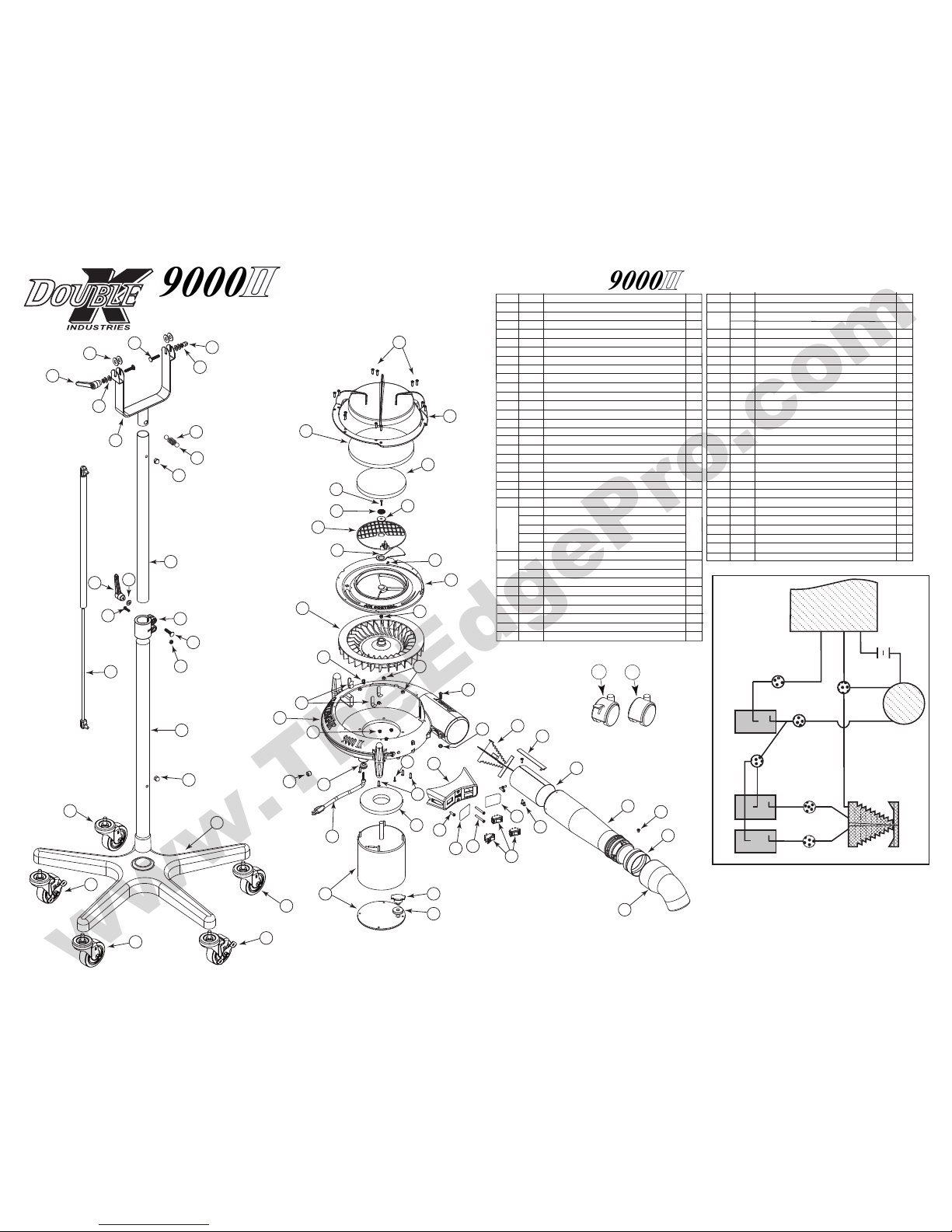
The stand tube assembly is pre-assembled and wrapped in paper. The stand tube
assembly is compressed and held in position by the center clamp. Loosen the handle
on the clamp and allow the spring to extend the tube assembly. Place the end of the
larger outer tube down into the center of the stand base. Twist and push down rmly
(see ref #55, 57 on parts diagram). On the dryer head assembly, move the yoke to
a 90-degree angle to the dryer. Lift the dryer and position over the assembled
stand and slide the tube of the yoke into the upper stand tube (see ref #49, 53). With
clamping handle still loose, raise or lower dryer to desired height and tighten stand
adjustment handle as explained in the next paragraph (see ref #45).
Stand Height Adjustment and Dryer Angle Adjustment:
Your dryer has "ratchet" type adjustment handles on the stand and the dryer. To
tighten an adjustment handle, turn the handle clockwise as far as is comfortable. As
necessary, for additional tightening, pull the handle out to disengage the "ratchet"
and while keeping the handle pulled out, turn the handle counter-clockwise to a
suitable position for continued tightening. Release the handle to engage the
"ratchet" again and repeat these procedures until the adjustment handle is tight.
Reverse the turning direction of these actions to loosen an adjustment handle.
NOZZLE: The nozzle at the end of the extension arm may be rotated to change the
direction of the airow. Simply rotate nozzle to the desired direction (see ref #42).
Optional Attachment: A hose and nozzle kit is available for the Challengair 9000
II. To attach the hose to the dryer, insert hose end into the arm extension nozzle. To
attach nozzles to the hose, simply push nozzle securely onto the hose end.
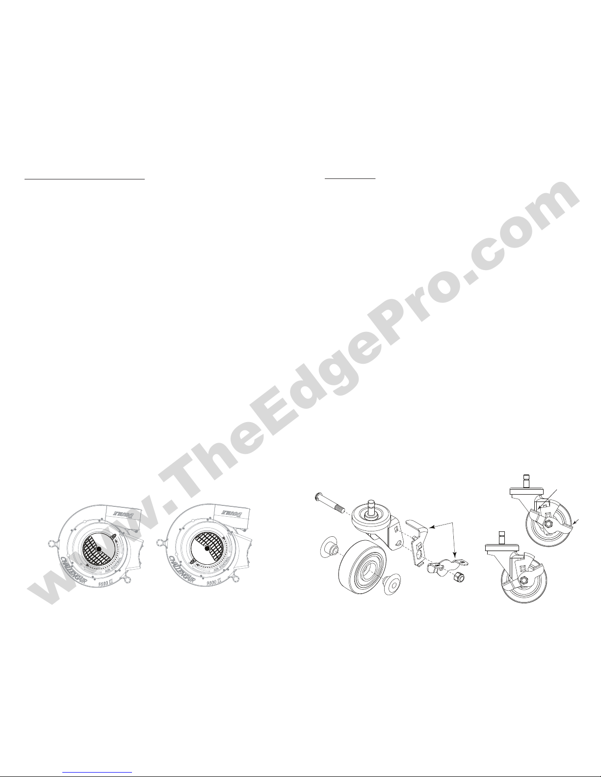
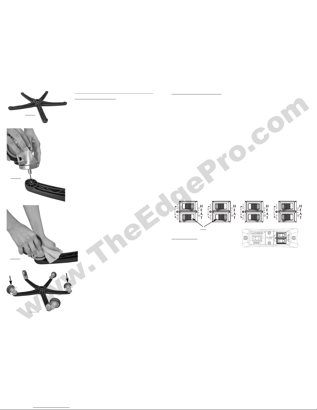
Dryer Stand: Your dryer stand has two locking casters to keep the dryer from rolling
inadvertently. To lock wheels, press down on the lock arm that has “ON” engraved on
it. To unlock, press down on the lock arm that has “OFF” engraved (see below). For
long life and smoother operation, avoid rolling casters through hair that has fallen
on the oor.
Locking
Wheels
Unlocked
Locked
ON
OFF
These parts only
on locking wheels
2
IMPORTANT SAFEGUARDS
WARNING: IMPORTANT SAFETY PRECAUTIONS! PLEASE READ
COMPLETELY BEFORE USING PRODUCT!
When using electrical appliances, especially in the presence of children and animals,
basic safety precautions should always be followed to reduce the risk of re, electric
shock, and personal injury, including, but not limited to the following:
1. Only use product for its intended purpose: animal drying.
2. Unplug unit when not in use.
3. Do not use extension cords with dryer.
4. Do not unplug unit by pulling on cord.
5. Do not expose dryer to rain or water.
6. Do not use or store dryer where it can fall or be pulled into tub or sink or stand-
ing water. If dryer falls into water . . . UNPLUG IT . . . Do not reach into the water!
7. Unplug unit before attempting any maintenance or service.
8. Do not put any object into dryer openings.
9. Keep loose clothing, jewelry and hair away from dryer openings.
10. Do not direct dryer air towards eyes or ears of people.
11. Never use dryer if it has a damaged cord or plug, has been dropped, damaged,
exposed to rain or water. Return to Double K Industries or an Authorized
Service Center for service.
12. Recommended operation by adults only. Use caution when working around
children.
13. Use only attachments recommended by Double K Industries.
14. Do not operate without lters in place. Keep lters clean, as dirty lters limit air
intake and may damage the motor or cause overheating.
15. Plug only into a properly grounded receptacle. Always make sure the amper-
age of the electrical outlet is sucient for the amperage rating of the product.
(See Product Specications for amperage rating of this product).
16. Do not attempt to perform any service or maintenance not outlined in instruc-
tion manual.
17. Do not attempt any product modications or alterations. Do not use, if any
parts or switches are damaged - send to an Authorized Service Center or
Double K Industries for service.
18. When servicing, use only Double K Industries parts.
Minimum Airow Position Maximum Airow Position
(View with Sound Cap removed to show lever position)

www.TheEdgePro.com
6
INSTRUCTIONS FOR INSTALLATION OF
WHEELS INTO BASE.
Place base on ground or sturdy table
with open side facing up. (g. 1)
Line up post on wheel assembly with
hole in base. (g.2)
Locking Wheel Placement.
Leave at least one non-locking wheel
between the 2 locking wheels so that
they are not next to each other. (g.4)
Placing a cloth between your hand
and the wheel assembly to protect
hand from sharp edges, press rmly
in a downward direction, using your
body weight to push wheel
post into base (g.3)
g. 1
g. 2
g. 3
g. 4
CONGRATULATIONS!
You’ve just purchased the Double K CHALLENGAIR 9000 ΙΙ, which produces large
volumes of warm air under pressure to make all of your animal drying tasks easier.
Your new dryer is designed to provide long, reliable service.
Please read this manual carefully and completely before beginning operation of
your dryer and keep in a convenient and safe place for future reference.
A warranty card is included with your dryer and should be lled out completely
and mailed to Double K Industries within 30 days of the purchase date of
your dryer to validate your warranty. Online registration available at
www.DoubleKIndustries.com.
Your CHALLENGAIR 9000 ΙΙ has a two year warranty covering the unit against
defects in materials and workmanship. Regular maintenance items such lters are
not included (see warranty card for complete warranty information). It is also impor-
tant to retain your sales receipt as proof of purchase should service ever be needed.
Limitations - Warranty does not cover shipping or transportation costs. Warranty
applies to original purchaser only. Proof of date of purchase is required. Warranty is
void if registration card is not mailed within 30 days of purchase or delivery.
Warranty does not cover abuse, accidents, acts of war, dropped product, improper
voltage, disassembly or alteration. Disassembly, repair or service by anyone other
than Double K Industries or a Double K Industries authorized service center will
void the warranty.
Operation:
Switches and Controls:
Your dryer has three rocker switches.
• To turn the dryer on: Flip the left switch to the “ON” position.
• To turn the dryer off: Flip the left switch to the “OFF” position.
Heat Control:
• Low Heat: Flip the top right switch to the “LOW” position while the bottom
right switch is in the o position.
• Medium Heat: Flip the bottom right switch to the “MED” position while the top
right switch is in the o position.
• High Heat: Flip both switches to “LOW” and “MED” position.
• To Turn O Heat: Flip both switches to the “OFF” position.
Air Control: The air volume on your dryer is controlled by the bae wheel located
under the lter on the top of the dryer. Rotate the lever attached to the wheel clock-
wise to reduce the air and counterclockwise to increase the air volume (see ref #9).
NOTE: The heat will also change as you increase or decrease the air volume, so you
may want to adjust the heat setting together with the air volume to achieve the
desired combination of air temperature and volume. 3
LOW HEAT MEDIUM HEAT HIGH HEAT OFF
*NOTE: White indicates depressed
side of rocker switch

www.TheEdgePro.com
43
44
45
46
49
46
45
56
59
59
58
58
58
57
24
21
20
19
16
15
13
9
8
6
5
3
18
52
55
14
43
54
53
52
2
4
7
10
11
17
35
36
37
34
38
39 40
41
42
32
31
30
25
27
28
26
23 29
22
33
14
12
14
51
50
47
48 1
17
EXPLODED DIAGRAM
TM
5
58b
59b
CORD
WHITE
GREEN
BLACK
BLACK
BLACK
BLACK
#5539
#5539
#5539
#5537
#5537
#5539
WHITEWHITE
MOTOR
ON / OFF
SWITCH
HEAT
SWITCH
HEAT
SWITCH
BLACK
BLACK
BLACK BLACK
HEATING ELEMENT
(BROWN
on 230V)
(BLUE on
230V)
Item# Part# DESCRIPTION Qty.
1 7020 Screw #8-16 x 5/8 Hi-Low PHP 12
2 7032 Sound Cap, 9000 II 1
3 7049 9000 II Sound Absorbing Disc 1
4 7029 9000 II Air Intake Filter 5.8 1
5 9036 Screw, 6-32 x 5/8 Slot Pan M/S 1
6 5538 Velcro for Filter Material 1
7 7014 Washer, #10 1”OD Fender 1
8 7010 Louver Intake Air Control 9000 II 1
9 7055 Secondary Louver Air Intake 9000 II 1
10 2091 Rivet Aluminum 3/8 x 1/8” 1
11 7065-1 9000 II Fan Housing Cut Out 1
12 5533 Nut, #6-32 UNF Locking Nylon Insert 4
13 7001 Impeller Fan Blade 1
14 5531 Nut #10-32 UNF Locking Nylon Insert 6
15 877 Cable Tie 7” Flat Nylon Natural 1
16 7065-H Housing, 9000 II Motor & Fan 1
17 7019 Screw #10-32 UNF x 3/4 PHP 2
18 5532 Cable Clamp 3/8” Plastic Black 3
19 5533 Nut, #6-32 UNF Keps Locking Grade 2 3
20 7030 1/2# OD 3/8”L 1/4”ID Nylon Spacer 2
21 534 Cord Grommet 1
22 9036 Screw, 6-32 x 5/8 Slot Pan M/S Z 2
23 10019 Screw #6-32 UNF x 1/2 PHP Self-Tapping 1
881 Cordset, 120v 14-Ft 14/3 SJTW
404 Cordset, China 230v
24 405 Cordset, Europe 230v 1
403 Cordset, Great Britain 230v
408 Cordset, Australia 230v
25 10109 9000 II Motor Filter 5.13 DIA 1
26 7002-1 Motor 1/3 HP 115v 1
7040-1 Motor 1/3 HP 230v
27 7051 Switch, 9000 II Manual Reset 1
28 7004 Gasket, 9000 II Manual Reset Switch 1
29 7009 Switch Box, 9000 II 1
30 7034 Screw #10-16 x 3/4 Hi-Low PHP 2
31 7061 Label“On / O” 9000 II Switch 1
32 7017 Screw #10-16 x 1-1/2 Hi-Low PHP 2
33 2148 Switch Rocker 20A 125 VAC 2-Pos Black/Red 3
Item# Part# DESCRIPTION Qty.
34 7062 Label, 9000 II Heat Control, Two-Switch 1
35 7044 115v Heating Element w/Fuse 1
7052 230v Heating Element w/Fuse
36 10122 Graphite Tape .015 x 1.0 x 50’ 1
37 9003 Screw #8 x 1/2 Sht, Metal PHP 4
38 7054 Shield For Heating Element 1
39 7066-1 9000 II Arm Extension 1
40 7073 8-32 x .25 Machine Screw 1
41 7046A Sleeve, 9000 II Arm Ext. 3”OD 1
42 7065-A Nozzle Directional, 9000 II Arm 1
43 7015 Bolt Screw 1/4-20 UNC x 1-1/4 Carriage 3
44 7013 Washer, 1.0 ODx.378 IDx.030 THK 4
45 7033 Handle Lever Adj. Black 2
46 10031 Washer, 1/4 SAE Flat Pltd 5
47 967 Washer Split Lock 1/4” 2
48 7031 Nut Acorn 1/4-20 UNC Zinc Plate 1
49 7011 9000 II Mounting Fork Black 1
50 7048 Mounting Fork Spring Compression 1
51 7047 1/2” Steel Ball, Mounting Fork 2
52 808 Nut 5/16-18 UNC Nickel Plated 2
53 838A Tube, 24”Inner Dryer Stand 1
54 7003 Clamp Stand Height Adjust 1
55 9020A Tube, 30”Outer Dryer Stand 1
56 830-1 Gas Spring 36”, Lift-O-Mat 1
57 9023 Stand Base, 26” 5-Leg Black 1
58 7064 Caster 3.5” Rubber Wheel 3
58b 9021 Caster (prior to 12/13) 3
59 7063 Caster 3.5” Rubber Locking Wheel 2
59b 9022 Locking Caster (prior to 12/13) 2
PARTS LIST
This manual suits for next models
1
Table of contents
Other Double K Industries Dryer manuals

Double K Industries
Double K Industries Challengair XSTREAM User manual

Double K Industries
Double K Industries Challengair 2000XL User manual

Double K Industries
Double K Industries Challengair 850 User manual

Double K Industries
Double K Industries CHALLENGAIR 560 User manual

Double K Industries
Double K Industries CHALLENGAIR 560 User manual
Popular Dryer manuals by other brands

Kenmore
Kenmore HE4 110.9508 Series Use & care guide

Samsung
Samsung DV9 T 2 Series user manual

Honeywell
Honeywell HCHD-310 installation guide

iStorm
iStorm HD0980-17 Operating instructions and parts manual

LG
LG DLGX3701W owner's manual

American Dryer Corp.
American Dryer Corp. Direct Spark Ignition ADG-530DSi II parts manual