6
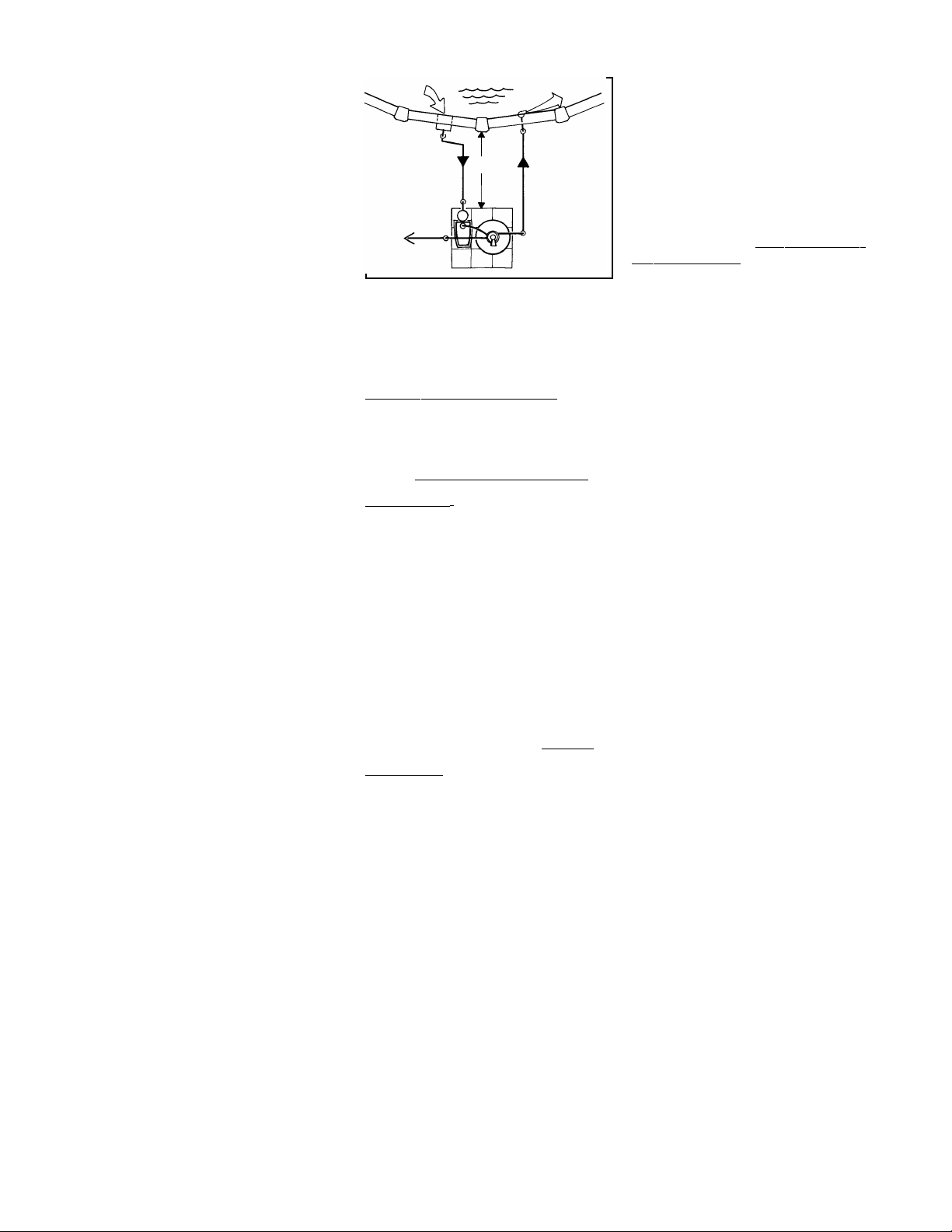
WASTE LINE HOOKUP
The discharge waste water will
contain pool water treatment chemi-
cals that may harm certain plants
and vegetation. Therefore, position
the discharge end of the waste line in
a safe, out-of-sight area capable of
accepting 150 to 200 gallons of
waste water. Install a 1-1/2" inside
diameter waste discharge hose (not
supplied) on the waste port near
where the sight glass is located on
the valve. Slip a 1-1/2" hose clamp
(not supplied) over one end of the
hose. Then, push hose onto the port
fully and tighten clamp firmly.
plugging the underdrain slots.
Because pool water is lost during
this operation (150 to 200
gallons) keep a close check on
pool water level. Never let water
level get so low that no water
flows to pump. Refill pool as
required.
5. Push down on the valve handle
and rotate to the FILTER position
and start pump. Note the
pressure reading on your pres-
sure gauge for future reference
of when to backwash.
6. Check all fittings and hoses for
leaks and correct if
necessary.
FILTER OPERATION
A newly filled pool is normally filled
with unfiltered water and usually
requires continuous filtering for 24 to
48 hours along with chemical treat-
ment of the pool water. Because all
pool installations vary in environmen-
tal conditions (wind, rain, airborne
debris, heat and pool use, etc.),
it is impossible to provide an accu-
rate filtering time for normal usage.
Use a trial and error method to
determine how long your filter must
operate each day. Generally, 6 to 8
hours of filtering each day is suffi-
cient to maintain pool clarity if the
pool chemical treatment is correct.
When possible, avoid operating your
filter during peak electricity demands
in your community. Check with your
local electric utility company for the
best times they recommend for
operating your filter pump.
WHEN TO BACKWASH
As your filter removes debris from the
pool water during the filtering pro-
cess, the return flow will gradually
reduce. Backwash when the pres-
sure gauge increases 5 to 7 pounds
above the clean filter starting pres-
sure. Normal backwash duration is
1-1/2 to 2 minutes or until water runs
clear.
VACUUMING YOUR POOL
When vacuuming your pool, the filter
must work harder. Consequently, all
of that debris is caught in the filter at
a very rapid rate. This causes a rapid
increase in filter pressure as will be
BACKWASH: Backwashing reverses
the flow of water through the filter to
flush out the dirt and debris, and
waste water is discharged to waste
from the valve body port with sight
glass.
FILTER TO WASTE: Place the valve
in the “Filter to waste” position after
backwashing your filter. (Normally,
for only 10 seconds.)
PUMP TO WASTE: This position
allows you to vacuum heavy debris
or larger amounts of settled contami-
nants from the pool floor directly to
waste.
RECIRCULATE POSITION: This
position allows you to increase the
water flow rate to circulate chemicals
throughout the pool more quickly.
Pool water passes through the valve
on top of the filter bypassing internal
filter components and travels back to
the pool at a rapid rate.
WINTERIZE POSITION: This posi-
tion allows you to drain trapped water
from the filter valve and relieve
compression on the rotor valve
gasket during winter storage.
CLOSED POSITION: When servicing
the filter, place the valve in the
“Closed” position to stop backflow of
water from pump. Stuff rag in return
fitting.
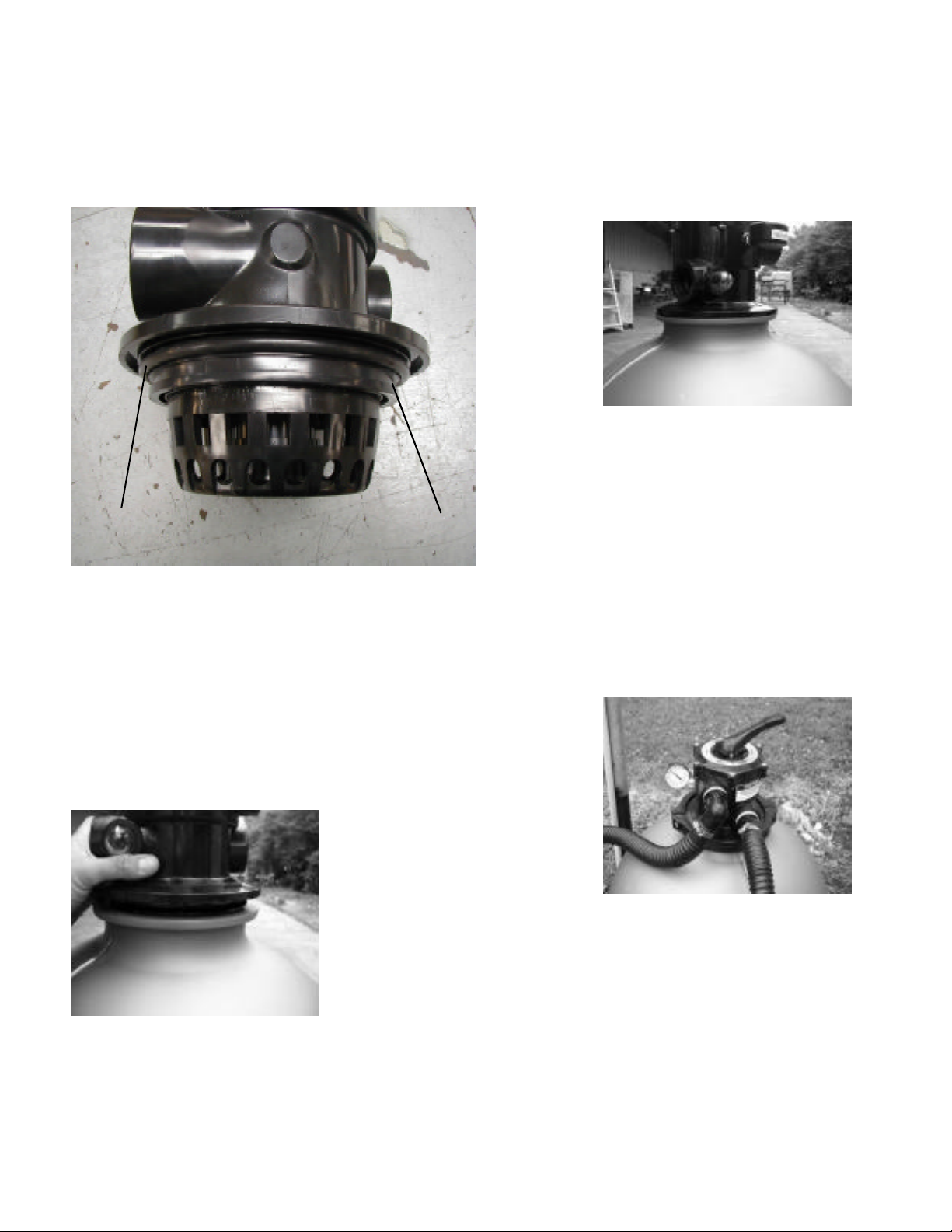
INITIAL START UP
Before you begin filtering your pool,
the filter sand must be backwashed
thoroughly to remove the extra fine
sand grains normally found in new
filter sand.
1. Loosen the pump strainer pot lid
to allow air to escape. Tighten lid
when water begins to flow
between strainer pot lid and
strainer body. Do not over
tighten.
2. Plug in your pump to the GFCI
protected receptacle. Refer to
WARNINGS.
3. Push down on the valve handle
and rotate to the BACKWASH
position. Make sure valve handle
indexes into the alignment slots
on valve.
4. Start pump. During this initial
start-up allow 4-5 minutes to
flush out the super-fine sand
grains to prevent them from
ELECTRICAL OUTLET
Refer to your pump owners guide for
detailed information pertaining to the
requirements and regulations for safe
electrical installation of the power
supply, receptacle outlet, switching
and ground fault interrupter.
FINISH FILLING POOL
Finish filling your pool, referring to
skimmer installation and pool assem-
bly instructions for proper water level.
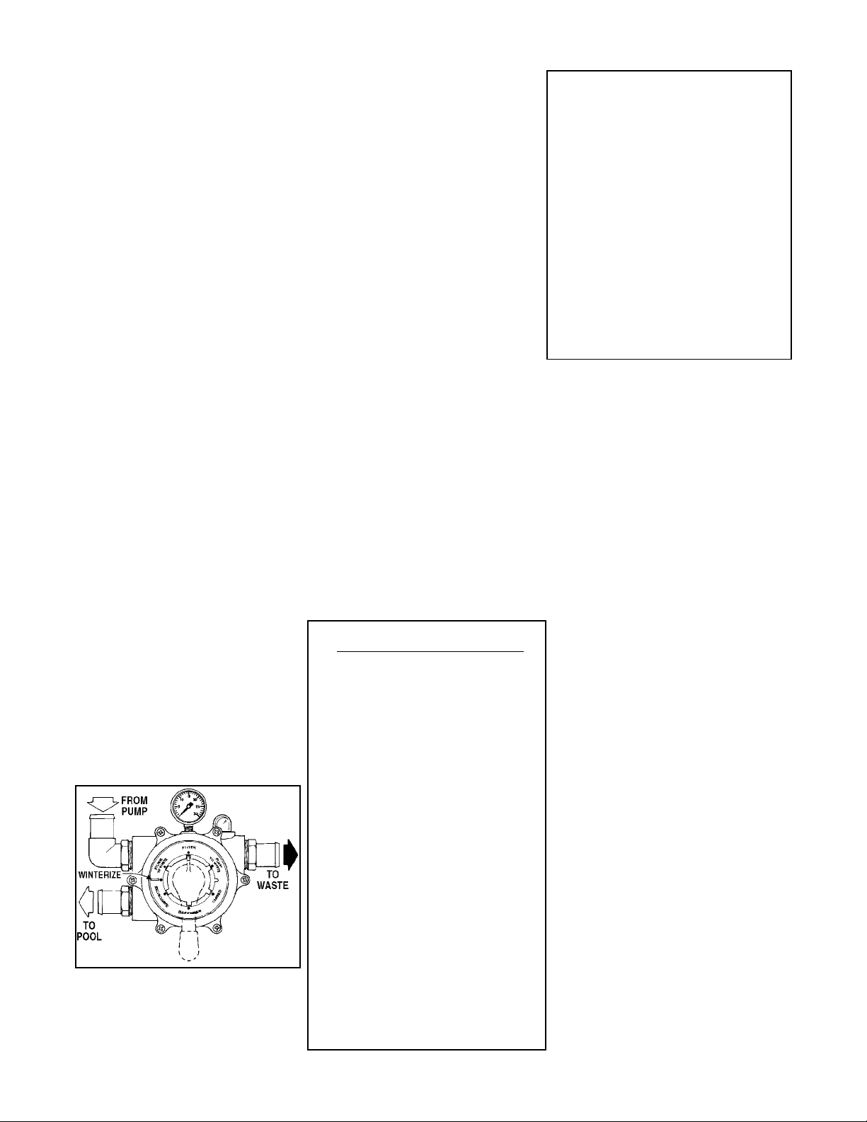
VALVE OPERATION
Your new filter has seven positions of
operation, which are explained below.
To change positions of the valve,
make sure the pump is OFF. Press
down on the valve handle enough to
free the locking tab. Rotate the
handle so the tab LOCKS in the
desired position.
FILTER: Normal pool filtering
position. May also be used when
vacuuming the pool.