Doughpro Proluxe Impact X1M User manual

Operations Manual
Impact X1M - Electro-mechanical Automatic Dough Press w/ Embedded Mold
Model #: DP3300M
WWW.PROLUXE.COM
Version: 51219
Rev 5

-1- DP3300 1410/20003/40002 5/03
Congratulations!
Your selection of the Doughpro DP3300
is a sound business decision. Doughpro
equipment is a result of the highest
quality engineering and time-tested
design. Your machine combined with
Doughpro’s reputation of innovation in
dough pressing equipment
manufacturing, insures the continuing
capability of delivering the best-
decorated product possible.
This manual describes installation,
operation, and maintenance procedures
for your new model DP3300.
Your model DP3300 machine will have
a long trouble-free life. Read this
manual carefully and keep it with your
machine; it’s your key to proper
operation and lasting service.
Installation
DOMESTIC
Use a separate 15 amp AC
circuit. Only industrial extension
cords with proper wire size
should be used; size 16/3 wire for
distance up to 25 feet, and size
14/3 for distance up to 50 feet.
INTERNATIONAL
Use a designated 16 amp AC
circuit. Only industrial extension
cords with proper wire size (2.5
sq. mm) shall be used.
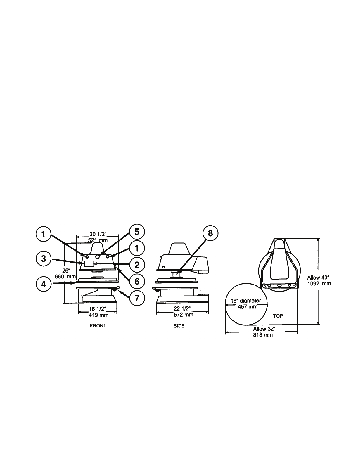
Make sure there is a proper electrical
wall outlet located within reach of the
cord and plug attached to the press.
Then place the press in an area which
allows for “swing clearance” of the
lower platen plus vertical and horizontal
clearance of the press itself.
Limited Machine Warranty
Doughpro warrants this dough press
machine, when operated under normal
conditions, to be free from
manufacturing defects in material and
workmanship for a period of one year on
parts and labor from the invoice date.
This warranty will be effective only
when Doughpro authorizes the original
purchaser to return the product to the
factory in South Gate, California freight
prepaid and only when the product, upon
examination, has proven to be defective.
This warranty does not apply to any
machine that has been subjected to
misuse, negligence or accident.
Doughpro shall not be liable for the
injury, loss or damage, direct or
consequential, arising out of the use or
the inability to use the product.
No claim of any kind shall be greater in
amount than the sale price of the product
or part to which claim is made.
This is the sole warranty given by the company, it is in
lieu of any other warranties, expressed or implied, in
law or in fact, including the warranties of
merchantability and fitness for a particular use, and is
accepted such by the purchaser in taking delivery of
this product.
Specifications
Electrical:
120V/60Hz/1450W/12.5Amps/AC
Also available; specify when ordering:
240V/50-60Hz/1450W/6.04Amps
Includes 68” cord and NEMA
approved plug.
Shipping Weight:
200lbs. (91kg)

-2- DP3300 1410/20003/40002 5/03
General Specifications
1. Piston Activation Buttons (2)
2. On/Off Power Switch
3. Digital Temperature & Time
Control – 0-200°F Temperature
Setting.
4. Upper Platen – Heated to help
the dough flow faster and more
evenly.
5. Disengage Switch – Releases
upper platen in case of
emergency.
6. Thickness Control Dial –
Controls the thickness of the
dough, (varies depending on size
of dough ball).
7. Lower Platen – Dough is placed
here; swings out for easy
removal of flattened dough.
8. Grease Port – Using a standard
grease gun, squeeze a food
approved, high temperature
grease into the port (once
monthly.).
Exterior Finish: Highly resistant white,
high gloss powder coat, approved for use
with food products. Molds are probrite
coated anti-stick surfaces.
Please Note: Part Number 1101017602-Ref#
92-REPLACEMENT MOTOR BRUSH SET ACTUATOR
Must be changed annually due to wear and tear.

-3- DP3300 1410/20003/40002 5/03
Safety Summary
WARNING
In case of power cord damage,
do not attempt to repair or
replace the power cord. Contact
the manufacturer or the local
distributor.
WARNING
Avoid touching hot surfaces
while operating the machine.
CAUTION
During normal operation, the
base of the machine must be
installed or placed above the wall
socket.
CAUTION
When servicing or cleaning the
machine, make sure that the
power cord is removed from the
wall socket.
Operation Timer/Temperature
Control
Solid State Controller
This controller has three (3) control
features:
1. Temperature – Temperature may
be set from 100°-325°F (38°-
163°C)
2. Time – Time may be set from 1
second to 10 minutes.
3. Counter – Cycle counter counts
the number of applications from
1 to 9999 (see additional Notes –
Counter).
Controller Operation
1. If the temperature is not being
displayed, press the MODE
button until temperature is
displayed.
2. Push and hold SET button and
simultaneously push UP (V) or
DOWN (W) arrow buttons to the
desired temperature setting.
3. Press the MODE button until
time is displayed.
4. Push and hold SET button and
simultaneously push UP (V) or
DOWN (W) arrow button to the
desired timer setting.
Dough Pressing Operations
SETTING CRUST THICKNESS
CONTROL:
Setting crust thickness is as simple as the
twist of a dial. By means of trial and
error, rotate the dial until desired
thickness is obtained. Note: Never
force the dial past its stop position or
damage could occur.

-4- DP3300 1410/20003/40002 5/03
PRESSING DOUGH:
First allow the upper platen to reach
programmed temperature. In most
cases, 150°F (65.5°C) is ideal, but trial
and error testing will determine the best
temperature for your dough.
For best results, your dough should be
proofed before pressing, but it will also
press directly out of your refrigerator.
Flour is not required to press a crust
and should not be dusted on any part of
the machine.
Determining the proper timer setting
also requires some trial and error until
you obtain the correction thickness and
diameter of your product. Start with five
(5) seconds and go up or down from
there. Remember that the timer does
not actuate until the upper platen mates
with the lower platen and resistance is
felt.
1. Apply a quick spray of a good
water based food release on the
lower platen. Doughpro offers
its own food release spray
NATURALLY CLEAR Model
No. DPPC1. (See our catalog
and price list for information.)
Note: This spray will not affect
the taste of your crust in any
way.
2. Place your pre-portioned ball of
dough in the approximate center
of the lower platen. Add another
dash of spray to the top of the
dough ball.
3. Close the platen and, with both
hands, press the two green
buttons on the face of the press.
4. Hold the buttons in until
resistance is felt then release at
once. The timer will actuate and
when the time cycle is
completed, the upper platen will
rise automatically (timer is preset
at factory for six (6) seconds, but
this is easily changed by
following the upcoming
instructions.)
5. Remove the crust, place on disc,
screen, pan or peel, add toppings
and bake.
ADDITIONAL NOTES:
Temperature
Note
Fahrenheit/Centigrade (Celsius)
Conversion
The temperature controller can
be programmed to display either
°F or °C. To change: Press the
MODE button until the
temperature is displayed, then
push and hold the SET button for
10 seconds.
Timer
•The controller has a count down
timer that automatically activates
a buzzer at the completion of the
application.
•Timer display is minutes:
seconds. Range is 00:00 to
10:00; Colons (:) flash while
timer is running.

-5- DP3300 1410/20003/40002 5/03
Note
The timer or buzzer may be
stopped while the handle is in the
down position by pressing both
the DOWN (W) arrow button and
the UP (V) arrow button
simultaneously. The timer will
automatically reset after the
handle is raised.
Counter
The controller has a built in cycle
counter.
•Press MODE button until the
counter is displayed.
•Counter display range is 0000 to
9999.
•To reset the cycle counter,
display the counter reading, then
push and hold both UP (V) and
DOWN (W) arrow buttons for 3
seconds until the counter resets
to zero (0000) on the display.
Serial Tags

-6- DP3300 1410/20003/40002 5/03
International Symbols
Preventative Maintenance Suggestions
The Doughpro DP3300 machines are
relatively maintenance free. For a long
and trouble-free life, the following
preventative maintenance should be
followed:
Daily Care:
1. Teflon coated platens: These
platens should only be cleaned
with mild soap and warm water
then wiped off with a clean, soft
cloth or soft sponge. Never use
steel wool or harsh abrasives or
you will cause costly damage.
*For DP3300M models*
Note that the top plate of the
lower platen is removable
without tools, for cleaning
purposes. To remove, simply
rotate the platen to the full open
position and remove the top
plate.
2. All other exterior surfaces:
Here again a daily wipe down
with mild soap and warm water
will do the job quite nicely.
Never use steel wool or harsh
abrasives or you will cause
costly damage.
Monthly Care:
Piston maintenance: The piston is the
one moving part that requires a grease
injection every two (2) to three (3)
months. A grease port located on the
right side of the upper platen piston is
provided for this purpose. Using a
standard grease gun fitted with an
extension, squeeze a food approved,
high temperature grease into the grease
port. *2 full squeezes from grease gun.
Service Problems:
Contact our factory or approved service
agency (U.S. only). Note: When
contacting factory for information, parts
or service instructions, it is of the utmost
importance that the serial number of the
machine be provided. This number can
be found on the serial plate located on
the rear of the machine.
Power On/Off

DOUGHPRO
DP3300 Trouble Shooting Guide
Symptom Probable Cause Action to be Taken
Ref. #'s on
Explosion
Drawing
Power Button on Digital Controller
face is depressed but doesn’t turn
on.
Power Cord is not plugged in.
Plug power cord into wall 's
receptacle and depress power
button on controller
68
Circuit Breaker is tripped off in the
site's breaker box
Reset circuit breaker that the Grill is
plugged into. Depress Power Button
to turn on.
___
Transformer has taken a electrical
surge and is damaged
Replace Transformer after you check
secondary side of transformer. If
working properly, you should
receive 12vdc.
91
Check voltage on the secondary side
of the Transformer. If you read
12VDC then you are receiving voltage
to the Controller.
Replace Controller. Controller
should be on once the power button
is depressed.
85
Possibly blown Fuse Replace fuse. 105
Digital Controller's LED's are
scrambled or randomly irratic. If
when turning on, the display will
first go to segment check
Possibly a componet on the Digital
Controller is damaged
Replace Digital Controller
85
Possibly control needs to reset
While unit is on (controller lit up)
Unplug unit, wait for 1 min. then
plug machine on and depress power
button.
___
Digital Controller on startup goes
through LED segment check (8888)
then to version # and then loops
back to to the above reboot.
The relay driver on the digital control
may be blown.
Replace Digital Controller.
85
Digital display shows PROB. No
heat on Upper Platen.
Sensor lost it's continuity as shown
on a muti-meter.
Disconnect prob that is open (no
continuity as shown on a multi-
meter. Must replace Sensor (RTD).
Do not cut and splice new sensor.
Install new 2000 ohm RTD sensor to
under side of Heat Platen and
reconnect to Controller.
41
When depressing the tactile button
on Digital Controller, nothing
happens.
The tactile buttons under the overlay
may be not close enough to activate.
Same goes if the buttons are already
pressed by overlay without
depressing button.
Carefully (no too much at one time
to avoid fracturing the traces on the
Controller) tighten the nuts on the
back of the Controller until button
activate. Same goes in reverse if
buttons are held down by the
overlay.
___
Digital display shows Relay and
Particular zone is over heating or
outer zone).
The Relay on the switched side is not
opening to regulate temperture.
Replace the Relay.
92
Beeper not functioning or
intermitten beeper sound.
Beeper on Digital Control board
failed.
Replace Digital Controller board 85

DOUGHPRO
DP3300 Trouble Shooting Guide
If setpoint is reached but slighty off
in temperature.
Offset may need to be calibrated and
adjusted.
Must call (800) 624-6717 ext. 129
for confidential instructions.
___
Heater Platen overheating
If the Relay (depending the year of
the model) on the coil side are
receiving 12vdc indicates the
Controller is functioning properly. On
the switching side of the relay, is
there 120 vac going to the heater in
question . If there is no voltage on
the to the switching side of the relay
to the heaters, the Relay is not
working properly
Replace Relay If the Controller's
heat-on LED is not lit indicating the
controller is working properly.
92
Thickness crank on top of press
turns endless
Set screws on crank maybe loose.
Make sure shaft is all the way on
thin setting by turning counter
clockwise then tighten the stacked
Allen screws (2 set screws on top of
each other) with allen wrench.
A5
Dough not having same thickness
across the press dough.
To adjust upper platen for level press
Underneath the housing you will
find 4, stacked hex bolts sitting over
the upper platen attach to the arm.
The top bolts are called locking
bolts. The 4 larger Hex Bolts below
are Adjustment Bolts. Break free the
4 Locking blts. With a open end
wrench adjust the A. bolts (1/8 turn
at a time where needed and test
with dough. After satisfied, tighten
the Locking bolts making sure not to
move the larger Adustment Bolts.
11 & 12
Power is on but hear a leaking of air
under the lower platen / Swing Arm
while Press is idle.
The O'rings are warn allowing the air
to pass through the cylinder
The cylinder needs orings, gasket
and new cylinder grease. Request
instruction sheet and need to order
P/N 110033 for the kit.
___
Press does not close when pressing
the two, green, start buttons
Did not simultaneously press the start
buttons exactly at the same time
Try pressing both buttons eactly at
the same time. This is a anti-tie-
down safety feature.
2
The Lower Platen switch mounted on
the base is not in contact to complete
circuit
Make sure the roller plunger comes
into contact (clicking noise). This is
also a safety feature that both
platens are aligned before
After activation Lower Platen and
when cycle is complete, the Lower
Platen either is very slow coming
down or doesn’t come down at all.
The Mufflers on the Solenoid Valve
are dirty and now allowing alr from
passing though.
Replace both Solenoid Valve
mufflers.
Upon activation, the Lower Platen is
slow to come up and down.
Filter encased in a black housing in
the back of the machine possilby is
dirty.
Replace Filter.

1
3
6
7
8
5
4X
4
12
4X 11 6X
10
15
14
13
9
22
21
19
20
2
34
C1
EXPDP3300M RB 072018
CUSTOMER MANUAL SHEET 1 OF 3
59
16
DP3300M
72X
5
106
2X

58
59
60
61
74X
62
63
62
63
64
65
66
67
68
7
2X
69
2X
8
2X
70
72X
69 2X
82X
73
74
75
71
72
11
78
79
77
76
80
2X
81
2X
82
2X
83
93 94 95
96
4X 97
4X
98
8X 99
8X
84
5
2X 85
5
2X 86 87
88 90
89
8
91
92
11
2X
5
2X
103
101
102
102
101
100
104
105
B1
B2
B4 B3
EXPDP3300M RB 072018
CUSTOMER MANUAL SHEET 2 OF 3
DP3300M

24
25
1
46
52
55
53
54
29
4X
45
56
57
49
50
36
38
2X
37
39
40 4X
44
43
41 4X
42 4X
23 38
37
32
33
28
31
4X
30
4X
29
4X
35
36
8
17
26
5
7
51
47
A2
A1
EXPDP3300M RB 072018
CUSTOMER MANUAL SHEET 3 OF 3
DP3300M
27 2X
63 2X
62
2X 74X
7

PARTSLISTFORMODELDP3300M
REF.# DESCRIPTION DP3300MA DP3300MB DP3300MAUB DP3300MAUC DP3300MGB DP3300MGC DP3300MCEB QTY.
1 BASEASSEMBLY 1107201101 1107201101 1107201101 1107201101 1107201101 1107201101 1107201101 1
2 RELIEFSTRAIN MPSS168 MPSS168 MPSS168 MPSS168 MPSS168 MPSS168 MPSS168 1
3 POWERCORD110969174 110969175 110172772177 110172772177 DP149203 DP149203 MPPW202 1
4 DRIVECARD,MOTOR 1101017501 1101017501 1101017501 1101017501 1101017501 1101017501 1101017501 1
5 SCREW,PHILLIPSPANHEAD8‐32x3/
8
SP83238 SP83238 SP83238 SP83238 SP83238 SP83238 SP83238 12
6 CLAMP,CABLE9/16"BUNDLE CC916 CC916 CC916 CC916 CC916 CC916 CC916 1
7 WASHER,SAE#8 WSAE8 WSAE8 WSAE8 WSAE8 WSAE8 WSAE8 WSAE8 17
8 SCREW,PHILLIPSPANHEAD8‐32x1/2 SP83212 SP83212 SP83212 SP83212 SP83212 SP83212 SP83212 8
9 WIREHARNESSLOWER 1101017053 1101017053 1101017053 1101017053 1101017053 1101017053 1101017053 1
10 PLATE,BASECOVER 11010954 11010954 11010954 11010954 11010954 11010954 11010954 1
11 SCREW,PHILLIPSPANHEAD,8‐32x1/
4
SP83214 SP83214 SP83214 SP83214 SP83214 SP83214 SP83214 9
12 FEET,RUBBER RF209 RF209 RF209 RF209 RF209 RF209 RF209 4
13 LOWERPLATENSTOPW/WASHE
R
110102130 110102130 110102130 110102130 110102130 110102130 110102130 1
14 WASHER,SAE3/8 WSAE38 WSAE38 WSAE38 WSAE38 WSAE38 WSAE38 WSAE38 1
15 NUT,HEX3/8‐16 NH3816 NH3816 NH3816 NH3816 NH3816 NH3816 NH3816 1
16 SWITCH,MICROROLLERPLUNGER BZ2RQ18A2 BZ2RQ18A2 BZ2RQ18A2 BZ2RQ18A2 BZ2RQ18A2 BZ2RQ18A2 BZ2RQ18A2 1
17 SCREW,PHILLIPSPANHEAD8‐32x1SP8321 SP8321 SP8321 SP8321 SP8321 SP8321 SP8321 1
19 FLANGEDBUSHINGMACHINED 110102167 110102167 110102167 110102167 110102167 110102167 110102167 1
20 SHIM,LOWERPLATEN 110379322055 110379322055 110379322055 110379322055 110379322055 110379322055 110379322055 1
21 HANDLELOWERPLATEN 1106301 1106301 1106301 1106301 1106301 1106301 1106301 1
22 KNOB(MUSHROOM)SWINGAWA
Y
110017 110017 110017 110017 110017 110017 110017 1
23 SHROUD,UPPERPLATEN 1109336 1109336 1109336 1109336 1109336 1109336 1109336 1
24 ARM,MACHINED 1106812101 1106812101 1106812101 1106812101 1106812101 1106812101 1106812101 1
25 SCREW,SOCKETHEAD3/8‐16x1SSH38161 SSH38161 SSH38161 SSH38161 SSH38161 SSH38161 SSH38161 1
26 CLAMP,CABLE1/2"BUNDLE CC12 CC12 CC12 CC12 CC12 CC12 CC12 1
27 CLAMP,CABLE3/8"BUNDLE CC38 CC38 CC38 CC38 CC38 CC38 CC38 2
28 MOTORSUPPORTBRACKET,HOUSING 1101017130 1101017130 1101017130 1101017130 1101017130 1101017130 1101017130 1
29 WASHER,SAE5/16 WSAE516 WSAE516 WSAE516 WSAE516 WSAE516 WSAE516 WSAE516 8
30 WASHER,5/16SPLITLOCK WL516 WL516 WL516 WL516 WL516 WL516 WL516 4
31 SCREW,SOCKETHEAD5/16‐18x1SSH516181D SSH516181D SSH516181D SSH516181D SSH516181D SSH516181D SSH516181D 4
32 ACTUATOR,90VDC3.5"STROKE 1101017601 1101017601 1101017601 1101017601 1101017601 1101017601 1101017601 1
33 DAMPINGWASHER 11086050 11086050 11086050 11086050 11086050 11086050 11086050 1
34 POST,LOWERPLATEN 11015960 11015960 11015960 11015960 11015960 11015960 11015960 1
35 TERMINAL,1/4Q.D.x16GAMALEF/I 1672FIN 1672FIN 1672FIN 1672FIN 1672FIN 1672FIN 1672FIN 2
36 TERMINAL,RING#8,14‐16GA,ETC#B237‐08X 1604 1604 1604 1604 1604 1604 1604 3
37 PIN,ACTUATOR 110791261 110791261 110791261 110791261 110791261 110791261 110791261 2
38 CLIP"E"RETAINING1/2 MPSC240 MPSC240 MPSC240 MPSC240 MPSC240 MPSC240 MPSC240 4
39 PISTONASSEMBL
Y
11086074 11086074 11086074 11086074 11086074 11086074 11086074 1
40 BOLT,LEVELADJUSTMENT 1109367 1109367 1109367 1109367 1109367 1109367 1109367 4
41 BOLT,HEX5/16‐18x1‐3/4GR5 BH51618134G5 BH51618134G5 BH51618134G5 BH51618134G5 BH51618134G5 BH51618134G5 BH51618134G5 4
42 CAP,VINY
L
SC0687 SC0687 SC0687 SC0687 SC0687 SC0687 SC0687 4
43 COLLAR,THICKNESSADJUSTMENT 11072086 11072086 11072086 11072086 11072086 11072086 11072086 1
44 SCREW,PANHEAD10‐32x3/8 SP103238 SP103238 SP103238 SP103238 SP103238 SP103238 SP103238 1
45 SCREW,PANHEAD6‐32X1/4NICKLEPLATEDSP63214 SP63214 SP63214 SP63214 SP63214 SP63214 SP63214 1
46 TERMINAL,RING#6 1601HT 1601HT 1601HT 1601HT 1601HT 1601HT 1601HT 1
47 ORING#2‐238N‐70,PISTON 238N70 238N70 238N70 238N70 238N70 238N70 238N70 1
49 WIRE,TGGT,14GA(HEATER) 110069 110069 110069 110069 110069 110069 110069 7.83FT
50 FORKTERMINAL14‐16GA,#10SCRE
W
1626 1626 1626 1626 1626 1626 1626 1
51 TFESHRINKTUBING 110131 110131 110131 110131 110131 110131 110131 .33FT
52 SENSORASSEMBLY2000OHMRTD 110949110 110949110 110949110 110949110 110949110 110949110 110949110 1
53 SCREW,SET3/8‐16x1/2CUP SST381612 SST381612 SST381612 SST381612 SST381612 SST381612 SST381612 1
54 SLEEVING,PVCWIRE OPVC1050 OPVC1050 OPVC1050 OPVC1050 OPVC1050 OPVC1050 OPVC1050 1.33FT
55 TERM.QD3/16X18/22GAINS.,ETCMOLEXAA2137 2280 2280 2280 2280 2280 2280 2280 2
PLDP3300MRB072018CUSTOMERMANUAL

PARTSLISTFORMODELDP3300M
56 WASHER,SAE#6 WSAE6 WSAE6 WSAE6 WSAE6 WSAE6 WSAE6 WSAE6 1
57 WIRE,TFE14GAGREEN WTFE14G WTFE14G WTFE14G WTFE14G WTFE14G WTFE14G WTFE14G 2.75FT
58 HOUSINGMACHINING 1105332201 1105332201 1105332201 1105332201 1105332201 1105332201 1105332201 1
59 SCREW,BUTTONHEAD1/4‐20x5/8 SB142058 SB142058 SB142058 SB142058 SB142058 SB142058 SB142058 2
60 THIN/THICKDECAL DPRO33001 DPRO33001 DPRO33001 DPRO33001 DPRO33001 DPRO33001 DPRO33001 1
61 SCREW,SET8‐32x1SST8321 SST8321 SST8321 SST8321 SST8321 SST8321 SST8321 1
62 WASHER,#8INTERNALTOOTHLOCK WLIT8 WLIT8 WLIT8 WLIT8 WLIT8 WLIT8 WLIT8 4
63 NUT,HEX8‐32 NH832 NH832 NH832 NH832 NH832 NH832 NH832 4
64 BRACKETASSEMBLYTHICK/THIN 11072082 11072082 11072082 11072082 11072082 11072082 11072082 1
65 CAM,PINTHICK/THINADJUSTMEN
T
11072083 11072083 11072083 11072083 11072083 11072083 11072083 1
66 THICKNESSADJUSTMENTKNOB 420085B14 420085B14 420085B14 420085B14 420085B14 420085B14 420085B14 1
67 BUSHING,TENSIONTHICK/THIN 11072081 11072081 11072081 11072081 11072081 11072081 11072081 1
68 SPRING,COMPRESSION 3742 3742 3742 3742 3742 3742 3742 1
69 WASHER,SPLITLOCK#8 WSL8 WSL8 WSL8 WSL8 WSL8 WSL8 WSL8 4
70 BRACKETMICROSWITCHTHICK/THIN 11072080 11072080 11072080 11072080 11072080 11072080 11072080 1
71 SCREW,ROUNDHEAD4‐40X5/8,SLOTTED SR44058 SR44058 SR44058 SR44058 SR44058 SR44058 SR44058 1
72 SCREW,ROUNDHEAD4‐40X1/2,SLOTTED SR44012 SR44012 SR44012 SR44012 SR44012 SR44012 SR44012 1
73 SWITCH,MICRO V15G31C25K V15G31C25K V15G31C25K V15G31C25K V15G31C25K V15G31C25K V15G31C25K 1
74 INSULATOR,MICROSWITCHNOME
X
700214 700214 700214 700214 700214 700214 700214 1
75 MICROSWITCHADJUSTINGPLATE 700213 700213 700213 700213 700213 700213 700213 1
76 SCREW,ROUNDHEAD4‐40X1SR4401SR4401SR4401SR4401SR4401SR4401SR44012
77 ADJUSTMENTTHICK/THINPLATE 11072084 11072084 11072084 11072084 11072084 11072084 11072084 1
78 SWITCH,MICROROLLERWHEE
L
1101017044 1101017044 1101017044 1101017044 1101017044 1101017044 1101017044 1
79 PLATE,SLIDETHICK/THIN 11072085 11072085 11072085 11072085 11072085 11072085 11072085 1
80 BUSHING,BUNDYWELDTHICK/THIN 11072069 11072069 11072069 11072069 11072069 11072069 11072069 2
81 WASHER,SAE#4 WSAE4 WSAE4 WSAE4 WSAE4 WSAE4 WSAE4 WSAE4 2
82 NUT,HEX4‐40 NH440 NH440 NH440 NH440 NH440 NH440 NH440 2
83 WIREHARNESSUPPER 1101017050 1101017050 1101017050 1101017050 1101017050 1101017050 1101017050 1
84 RELAY30A/250VAC 1101017520 1101017520 1101017520 1101017520 1101017520 1101017520 1101017520 1
85 RELAY,MECHANICAL30AMP 110942520 110942520 110942520 110942520 110942520 110942520 110942520 1
86 FUSEHOLDER 110729009 110729009 110729009 110729009 110729009 110729009 110729009 1
87 FUSE,20AMP 1101017008 1101017008 1101017008 1101017008 1101017008 1101017008 1101017008 1
88 SCREW,PHILLIPSFLATHEAD6‐32x3/8 SF63238 SF63238 SF63238 SF63238 SF63238 SF63238 SF63238 1
89 TERMINALBLOCK2STAGEDOUBLE 6012 6012 6012 6012 6012 6012 6012 1
90 MARKERSTRIP2STAGEDOUBLE MS6012 MS6012 MS6012 MS6012 MS6012 MS6012 MS6012 1
91 RELAY,SOLIDSTATE MPR90217 MPR90217 MPR90217 MPR90217 MPR90217 MPR90217 MPR90217 1
92 TRANSFORMER 11096975 11096975 MPPT700R MPPT700R MPPT700R MPPT700R MPPT700R 1
93 OVERLAYDIGITALCONTROLPANE
L
ODP1300 ODP1300 ODP1300 ODP1300 ODP1300 ODP1300 ODP1300 1
94 CONTROL,FACIAPLATEASSEMBL
Y
11086027 11086027 11086027 11086027 11086027 11086027 11086027 1
95 DIGITALCONTRO
L
1101017052 1101017052 1101017052 1101017052 1101017052 1101017052 1101017052 1
96 SPACER,NYLON1/4 110969111 110969111 110969111 110969111 110969111 110969111 110969111 4
97 WASHER,STEEL 311150019 311150019 311150019 311150019 311150019 311150019 311150019 4
98 WASHER,#6INTERNALTOOTHLOCK WLIT6 WLIT6 WLIT6 WLIT6 WLIT6 WLIT6 WLIT6 8
99 NUT,HEX6‐32 NH632 NH632 NH632 NH632 NH632 NH632 NH632 8
100 BUTTONBLACKMUSHROOM P9ARB3N P9ARB3N P9ARB3N P9ARB3N P9ARB3N P9ARB3N P9ARB3N 1
101 SWITCH,MOM P9XPLOSO P9XPLOSO P9XPLOSO P9XPLOSO P9XPLOSO P9XPLOSO P9XPLOSO 3
102 CONTACTN/OSCRE
W
110101751 110101751 110101751 110101751 110101751 110101751 110101751 3
103 GREENMUSHROOMBUTTON P9ARB3
V
P9ARB3
V
P9ARB3
V
P9ARB3
V
P9ARB3
V
P9ARB3
V
P9ARB3
V
2
104 SCREW,SET8‐32x3/16 SST832316 SST832316 SST832316 SST832316 SST832316 SST832316 SST832316 1
105 FITTING,ZERK1/4‐28 B792 B792 B792 B792 B792 B792 B792 1
106 SCREW,BUTTON1/4‐20X3/4 SB142034 SB142034 SB142034 SB142034 SB142034 SB142034 SB142034 2
A1 UPPERPLATENWIREONL
Y
DP18031120K DP18031240K DP18031240K DP18031220K DP18031240K DP18031220K DP18031220K 1
A2 UPPERPLATENASSEMBLYCOMPLETE DP18031120AK DP18031240AK DP18031240AK DP18031220AK DP18031240AK DP18031220AK DP18031220AK 1
PLDP3300MRB072018CUSTOMERMANUAL

PARTSLISTFORMODELDP3300M
B1 SWITCHADJUSTMENTASSEMBL
Y
110729100 110729100 110729100 110729100 110729100 110729100 110729100 1
B2 THICK/THINADJUSTMENTKNOBASSEMBLY 11072082A 11072082A 11072082A 11072082A 11072082A 11072082A 11072082A 1
B3 STOPBUTTONASSEMBL
Y
11051850 11051850 11051850 11051850 11051850 11051850 11051850 1
B4 STARTBUTTONASSEMBLY 11051845 11051845 11051845 11051845 11051845 11051845 11051845 2
C1 LOWERPLATENASSEMBL
Y
11076632K 11076632K 11076632K 11076632K 11076632K 11076632K 11076632K 1
PLDP3300MRB072018CUSTOMERMANUAL


Warranty & Return Policy
Proluxe warrants all products manufactured by it against defects in workmanship or materials from the date of purchase for a period of
(1) year on parts and labor. This warranty applies to only equipment purchased and used in the United States. Warranty period
shall begin when equipment ships. Warranty travel shall only be covered for 60 miles. Limited lifetime warranty on heating
elements.
ALL WARRANTY SERVICE CALLS MUST BE APPROVED BY PROLUXE. IF THIS PROCEDURE IS NOT FOLLOWED,
WARRANTY SERVICE WILL NOT BE COVERED. WARRANTY SERVICE WILL BE PAID ON STRAIGHT TIME, OVERTIME WILL
NOT BE COVERED.
Exclusions:
1. WOOD / GAS FIRED OVENS: PROLUXE warranty applies to the main body of the oven being steel / refractory and insulation shall
be free from defects in materials and workmanship for a period of four years from the date of purchase. The gas equipment shall be
free from defects in materials and workmanship for a period of one (1) year
from the date of purchase. Lifetime warranty against cracks on oven floor.
2. Air compressors are excluded from this warranty, but PROLUXE may act as a warranty expeditor in certain instances regarding
these compressors. The air compressor manufacturer provides a limited warranty
and a copy of this warranty is furnished with all compressors sold by PROLUXE. For prompt handling of compressor warranty claims
the instructions of the compressor manufacturer must be adhered to.
3. Equipment built to special order as well as accessories cannot be canceled and are not returnable unless defective within the
terms of this warranty.
4. In no event shall PROLUXE be liable for consequential damages arising out of the failure of any of its products if operated
improperly, altered or caused by normal wear or damage by operator abuse.
5. BC2325 pedestal warranty disclaimer: Pedestals shall only be covered under warranty if they have been cleaned using the factory
approved cleaning method. Cracked or damaged pedestals must be inspected by the factory before warranty is authorized.
6. Limited lifetime warranty on heating elements: If replacement is needed, Proluxe will send the new part at no charge but labor will
not be covered unless the unit is still under the 1 year manufacture warranty.
Returned Merchandise Policy:
Should it become necessary to return any of the company’s products, the following instructions must be adhered to: First,
contact our customer service department for approval and a return authorization number. Please have the serial number
of your item available at that time. All merchandise must be shipped freight prepaid by customer or service agency.
Subject to the inspection of the product by the company, a restocking charge of 20% of the Net purchased price paid to
PROLUXE will be assessed. Merchandise may not be returned for credit without prior written approval of PROLUXE. Collect shipments
will not be accepted. No returns after 60 days of original shipment date on machines. Purchased parts may not be returned after 30
days.
If upon inspection by PROLUXE or its authorized agent it is determined the equipment has not been used in an appropriate manner,
has been modified, or has not been properly maintained, or has been subject to misuse,
misapplication, neglect, abuse, accident, unauthorized modification, damage during transit, delivery, fire, flood, act or war,
riot or act of God, then this warranty shall be deemed null and void.
Terms & Conditions:
1. Prices indicated in the PRICE LIST are suggested retail prices and are shown in U.S. DOLLARS.
2. Terms of Payment: NET 30 days.
3. NEW ACCOUNTS: Satisfactory credit information must be provided before open account status can be extended.
Unless agreed otherwise, all shipments will be made C.O.D., CASH IN ADVANCE.
4. PRICING: Prices, specifications, model numbers, capacities and accessories are subject to change without notice.
5. FREIGHT / ROUTING: Method of shipment will be determined by PROLUXE unless otherwise
advised by PURCHASER.
6. DAMAGED CLAIMS: All merchandise shipped at purchaser’s risk. Inspection must be made by purchaser at time
goods are received. If goods are damaged, the PURCHASER shall request that the agent of the transportation
company make a written notation on the proper shipping documents immediately and then file a claim for damage.
GOODS DAMAGED IN SHIPMENT ARE NOT RETURNABLE.
7. RETURNS: Machines may not be returned after 60 days. Purchased parts may not be returned after 30 days. A
restocking fee of 20% will be assessed on non-warranty returns.
8. TAXES: Prices indicated herein DO NOT include State, Federal, Local or foreign taxes or duties, nor do they include
fees, permits, insurance or other levies, all of which are the responsibility of the purchaser.
9. All orders are subject to acceptance by PROLUXE.
10. Possession of this price list shall not be considered an offer to sell.
Rev 12916
This manual suits for next models
1
Table of contents
Other Doughpro Commercial Food Equipment manuals

Doughpro
Doughpro Proluxe DP2010PIPG User manual

Doughpro
Doughpro DP1100 User manual

Doughpro
Doughpro PP1818 Quick start guide

Doughpro
Doughpro Proluxe DP3300BZ User manual

Doughpro
Doughpro Proluxe DP2010MYE User manual

Doughpro
Doughpro Proluxe DP2000SE User manual

Doughpro
Doughpro PROLUXE DP1350 User manual
Popular Commercial Food Equipment manuals by other brands

saro
saro ES 901 S/S Top 0/4 operating instructions

Omcan
Omcan PE-BR-0010 instruction manual

Keysight Technologies
Keysight Technologies 11636C Operating and service manual

Fri-Jado
Fri-Jado BS3i user manual

Hussmann
Hussmann TY3ECRC Installation & operation guide

Salvis
Salvis Smartline SILOFRIT Series installation instructions