2.4.4. Location and Piping
An improperly designed piping system or unit installation
WILL significantly reduce package performance and life.
Blackmer recommends the following piping system
layout and unit installation.
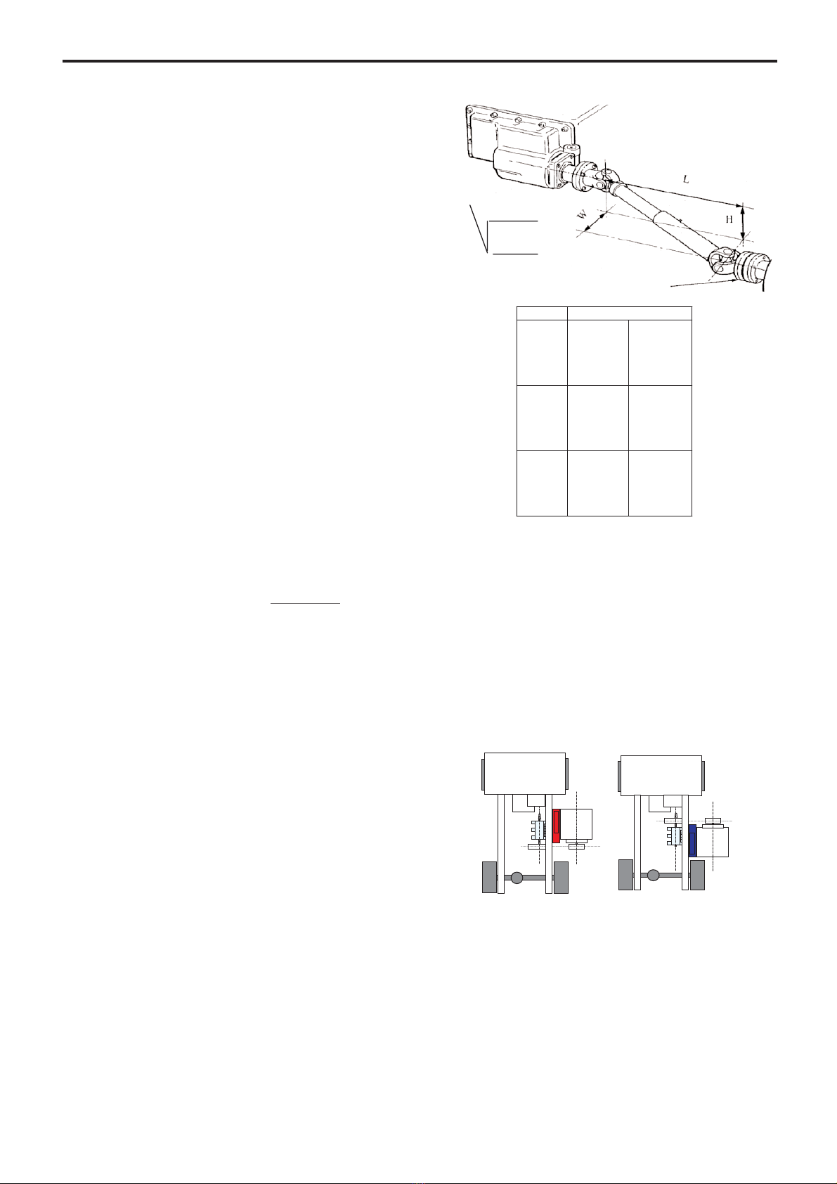
1. Piping MUST be properly supported to prevent any
piping loads from being placed on the pump.
2. Intake piping and fittings MUST be at least as large in
diameter as the pump intake connection.
3. Minimize the number of intake line fittings (valves,
elbows, etc.) and piping turns or bends.
4. Discharge piping MUST be free of all leaks.
2.5 Electrical wiring
The TYPHON 1000 INTERCOOLER package needs
electrical power to propel the fan pulsing the cooling air
through the radiator.
To prevent unwanted operations of the fan, a temperatu-
re switch set to 78°C on the climb and 68°C on the fall
controls the supply of power to the fan. This system will
prevent power consumption on the package when the
system is not operating.
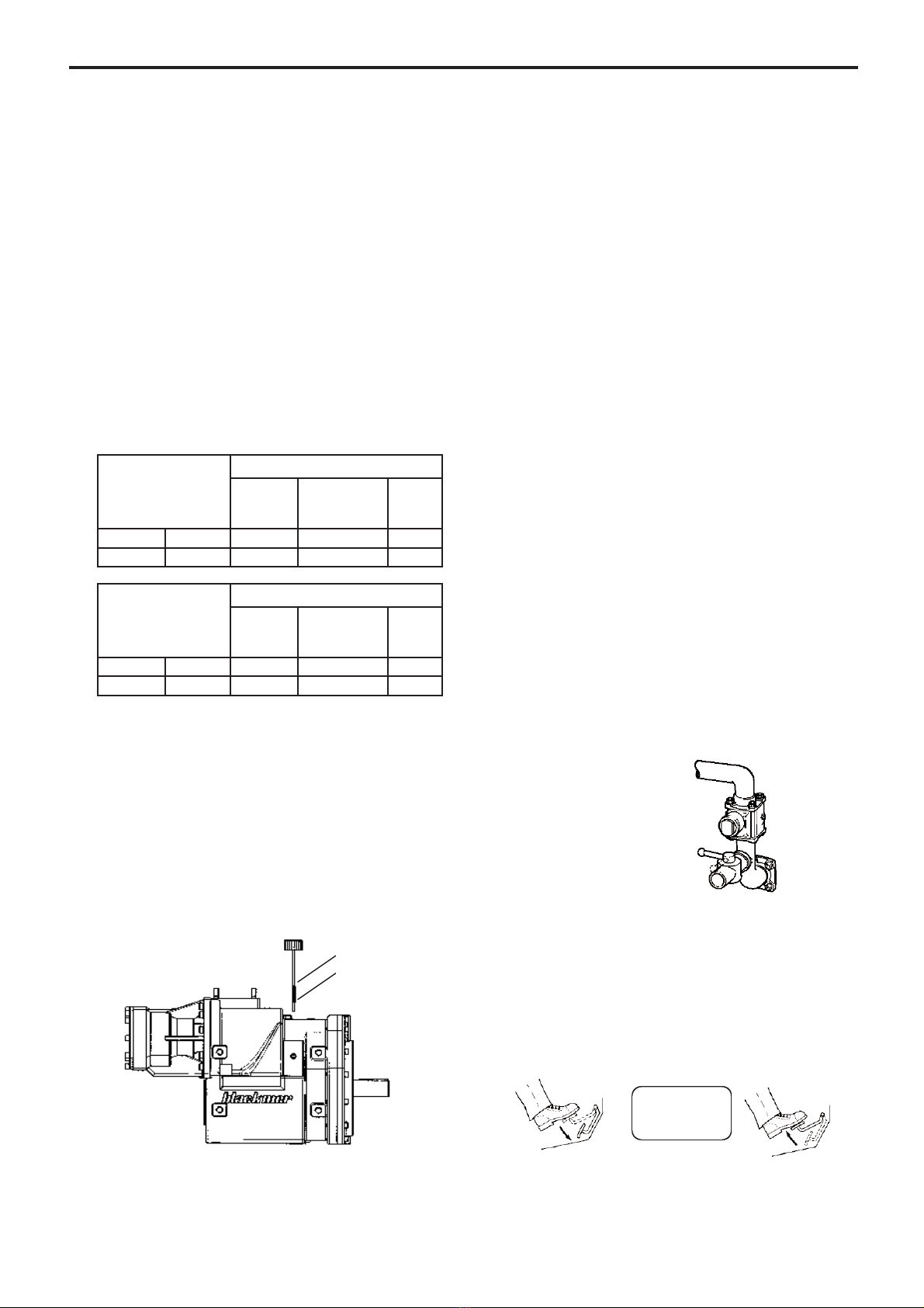
The systems are equipped with a button, which controls
the fan speed. When the button is on the cool position,
the fan works at max speed, and the discharge tempe-
rature of the compressor is at its minimum. When the
button is on the hot position, the fan is only supplied with
12 V, and the discharge temperature of the compressor
will remain above 150°C. You may want to use those
temperatures to dry the trailer after a cleaning cycle.
DO NOT FORGET TO CONNNECT THE 12 V
CONNEXION, as this will lead the package to work
without cooling and will create temperature inside the
package the fan is not abble to handle.
This thermal switch needs the package to stabilize in
temperature before operating. This may take several
minutes, depending on the ambiant temperature. Typical
start up time for ambiant temperature of 20°C is 150 s at
2 bar package discharge pressure.
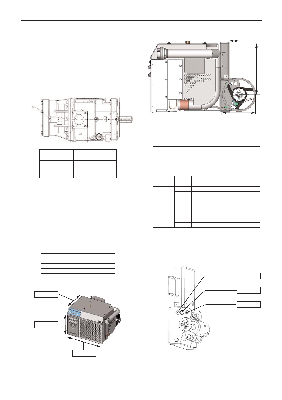
2.5.1 Electrical wiring diagram
2.5.2 Connection procedure
The supply line used to power the intercooler package
must be protected by a 16 Amps fuse on both the 12 V
and 24 V supply lines to prevent property damage and
body injuries.
The 3 wires to connect the main power supply to the bat-
tery are stripped 10 cm at the end of an 8 m long cable.
Color code for the wires :
• Blue . . . . . . . . . . . . . . . . .24 V connection
• Brown . . . . . . . . . . . . . . . .12 V connection
• Yellow / green . . . . . . . . . .Grounding connection
The electric cable connecting the Typhon intercooler to
the power supply should be properly supported to pre-
vent wear of the insulation coating.
The electrical wiring should be made in order to avoid
shorts to ground and microcuts.
DO NOT FORGET TO CONNNECT THE 12 V
CONNEXION, as this will lead the package to work
without cooling and will create temperature inside the
package the fan is not abble to handle.
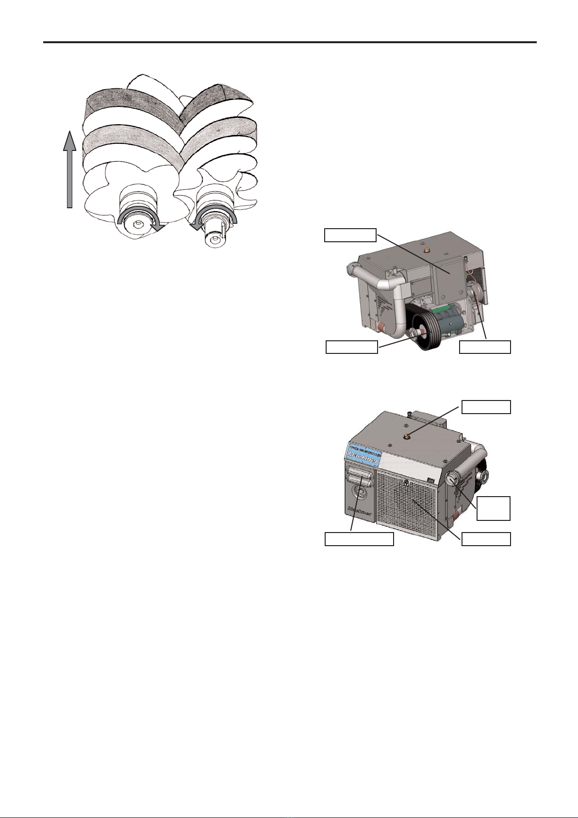
2.6 Instrumentation connections
On gauges are available on the Intercooler and Cover
packages to check the clogging of the inlet filter,
This gauge has a resettable red clogging alarm. Any
operation with the clogging alarm on will lead to prema-
ture failure of the compressor and potential bodily injury
or property damage.
2.7 Chair modification
If the top of the chair is too high for a given application,
it is allowed to cut the extra high, provided that the chair
is closed on top by a steel plate equivalent to the one
delivered with the package, welded according to
ISO 5817 category C.
THE POWER SOURCE SHOULD BE SWIT-
CHED OFF PRIOR TO ANY ELECTRIC
WORK ON THE INSTALLATION TO PRE-
VENT ELECTROCUTIONS, PROPERTIES
DAMAGES AND INJURIES.
WARNING
Hazardous voltage.
Can shock, burn or
cause death.
9/21
NT 1401-F00 12.05 Cold front outlet Intercooler TYPHON e
22..
IINNSSTTAALLLLAATTIIOONN
((ccoonnttiinnuuoouuss))