Dover PSG Mouvex MX12 Guide

MX12
SCREW COMPRESSORS
INSTRUCTIONS 1401-AL00 e
Section 1401
Effective October 2020 (2)
Replaces October 2020
Original instructions
Your distributor :
Z.I. La Plaine des Isles - F 89000 AUXERRE - FRANCE
Tel. : +33 (0)3.86.49.86.30 - Fax : +33 (0)3.86.49.87.17
contact.mouvex@psgdover.com - www.mouvex.com
INSTALLATION
OPERATION
MAINTENANCE
SAFETY
STORAGE
WARRANTY :
MX12 screw compressors are covered 24 months by warranty within the limits mentioned in our General Sales Conditions. The use of the
BSC3 oil carries our warranty from 24 to 36 months. In case of a use other than that mentioned in the Instructions manual, and without
preliminary agreement of MOUVEX, warranty will be canceled.
Warranty extension with oil BSC3 : See § WARRANTY.
This Instructions only contains bare shaft machine information.
It is imperative to have in complement the accessories instructions, also the parts list before
installing the equipment.

2/18
NT 1401-AL00 10 20 (2) MX12 e
MOUVEX TRUCK SCREW COMPRESSOR
SAFETY, OPERATION AND MAINTENANCE INSTRUCTIONS
MODEL : MX12
REMARKS :
MOUVEX truck screw-type compressors MUST be installed in sys-
tems designed by qualified personnel. The installation MUST be in
compliance with local standards, national regulations and rules of
safety.
This manual is designed to permit installation and commis-
sioning of MOUVEX truck screw-type compressors and MUST
accompany the compressor.
Maintenance of MOUVEX screw-type compressors must ONLY be
carried out by qualified technicians. This maintenance must meet
local and national standards as well as all safety regulations.
Read this manual, including all instructions and warnings, in
full BEFORE any use of MOUVEX compressors.
Do not remove the warning and use label stickers that are
found on the compressors.
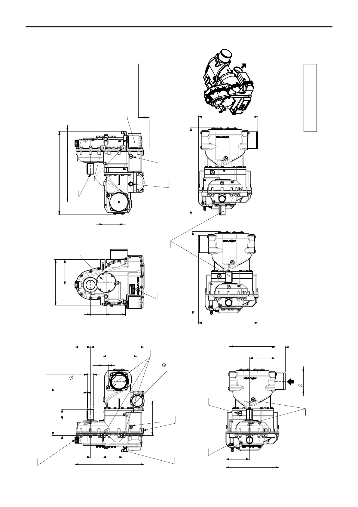
1. OVERALL DIMENSIONS . . . . . . . . . . . . . . . . . . . . . . . . . .4
2. GENERAL DATA . . . . . . . . . . . . . . . . . . . . . . . . . . . . . . . .7
2.1 Principle of operation . . . . . . . . . . . . . . . . . . . . . . . . . .7
2.2 Technical characteristics . . . . . . . . . . . . . . . . . . . . . . . .7
2.3 Operating ranges . . . . . . . . . . . . . . . . . . . . . . . . . . . . .8
3. INSTALLATION . . . . . . . . . . . . . . . . . . . . . . . . . . . . . . . . .9
3.1 Mounting location . . . . . . . . . . . . . . . . . . . . . . . . . . . . .9
3.2 Fixations . . . . . . . . . . . . . . . . . . . . . . . . . . . . . . . . . . . .9
3.3 Connections . . . . . . . . . . . . . . . . . . . . . . . . . . . . . . . .10
3.4 At suction . . . . . . . . . . . . . . . . . . . . . . . . . . . . . . . . . . .11
3.5 Discharge . . . . . . . . . . . . . . . . . . . . . . . . . . . . . . . . . .11
3.6 Drive . . . . . . . . . . . . . . . . . . . . . . . . . . . . . . . . . . . . . .11
4. USE OF COMPRESSOR . . . . . . . . . . . . . . . . . . . . . . . . . .13
4.1 Lubricant recommendations . . . . . . . . . . . . . . . . . . . .13
4.2 Filling of lubricant . . . . . . . . . . . . . . . . . . . . . . . . . . . .13
4.3 Operation . . . . . . . . . . . . . . . . . . . . . . . . . . . . . . . . . .14
4.4 Starting-up . . . . . . . . . . . . . . . . . . . . . . . . . . . . . . . . .14
5. MAINTENANCE . . . . . . . . . . . . . . . . . . . . . . . . . . . . . . . .15
5.1 Maintenance schedules . . . . . . . . . . . . . . . . . . . . . . .15
5.2 Compressor oil change procedure . . . . . . . . . . . . . . .15
5.3 Air filter replacement procedure . . . . . . . . . . . . . . . . .15
5.4 Drive train inspection . . . . . . . . . . . . . . . . . . . . . . . . .15
5.5 Check valve and relief valve inspection . . . . . . . . . . .15
6. TROUBLESHOOTING . . . . . . . . . . . . . . . . . . . . . . . . . . .16
7. WARRANTY . . . . . . . . . . . . . . . . . . . . . . . . . . . . . . . . . .17
7.1 Warranty claims . . . . . . . . . . . . . . . . . . . . . . . . . . . . .17
7.2 24-months warranty extension with BSC3 oil . . . . . . .17
8. STORAGE CONDITIONS . . . . . . . . . . . . . . . . . . . . . . . . .17
8.1 Compressor . . . . . . . . . . . . . . . . . . . . . . . . . . . . . . . .17
8.2 BSC oil . . . . . . . . . . . . . . . . . . . . . . . . . . . . . . . . . . . .17
9. SCRAPPING . . . . . . . . . . . . . . . . . . . . . . . . . . . . . . . . . .17
10. CERTIFICATE OF CONFORMITY . . . . . . . . . . . . . . . . .18
TABLE OF CONTENTS Page
ADDITIONAL DOCUMENTATION
The table below gives the list of instructions in addition
to this central instruction :
MX12
application Instructions
Check and relief valve NT 1401-E00
Torque limiter NT 1401-B00
Air cooler NT 1401-AJ00
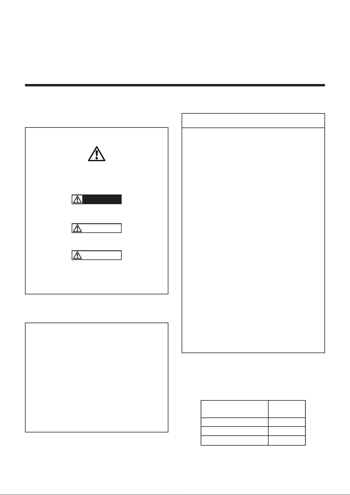
Definition of safety symbols
This is a SAFETY ALERT SYMBOL.
When you see this symbol on the product, or in the manual,
look for one of the following signal words and be alert to the
potential for personal injury, death or major property damage.
Warns of hazards that WILL cause serious personal injury,
death or major property damage.
Warns of hazards that CAN cause serious personal injury,
death or major property damage.
Warns of hazards that CAN cause personal injury or property
damage.
NOTICE
Indicates special instructions which are very important and
must be followed.
DANGER
WARNING
CAUTION

3/18
NT 1401-AL00 10 20 (2) MX12 e
SAFETY CHECK LIST
1. Before operating the compressor, ensure the vessel to which the
compressor is connected is certified to withstand the pressure.
2. Verify adequately sized relief valves have been fitted to protect the
vessel. Do not use solvents or inflammable products for cleaning
the pipelines and the accessories.
3. Gas/air mixtures which are potentially volatile/explosive must not be
introduced or allowed to be introduced into the compressor.
4. All pressure vessel and piping connected to the compressor must
be isolated and in a safe operating condition.
5. Operators should wear ear protection when operating truck mount-
ed compressors.
6. There are components within the compressor of sufficient weight
to cause injury if mishandled. Use proper lifting devices as neces-
sary.
7. Where necessary, this equipment should be grounded to control
static electricity.
8. The temperature of the air leaving the compressor is elevated
above ambient due to air compression. Check that the elevated
temperatures do not adversely affect the product and any material
used in design of the system. Attach clearly marked warning signs
to warn of potentially hot surfaces on the compressor, piping and
accessories which will burn if touched.
9. Mounting of the compressor must be correctly engineered and the
compressor must be properly secured. Refer to the Compressor
Mounting section of this manual.
NOTICE :
MOUVEX COMPRESSORS ARE DESIGNED TO PRODUCE COM-
PRESSED AIR. NOT TO PUMP LIQUIDS, LIQUEFIED GASSES OR
POWDERS THOUGH THE COMPRESSOR.TO DO SO WOULD VOID
THE WARRANTY.
LIFTING POINTS :
To connect 1 lifting ring to the item (1) alone or 2 lifting rings
to the items (1) + (2).
1
2
WARNING
IT IS IMPERATIVE TO APPLY THE
TRUCK PARKING BRAKE AND TO
BLOCK THE WHEELS BEFORE ANY
INTERVENTION DUE TO RISKS OF
SERIOUS BODILY INJURIES OR PRO-
PERTY DAMAGE.
Hazardous machinery
can cause severe
personal injury or
property damage.
WARNING
CONTENTS OF THE COMPRESSOR,
TANK, PIPING, AND FILTERS COULD
BE HAZARDOUS TO HEALTH.
TAKE ALL NECESSARY PRECAUTIONS
WHEN PERFORMING COMPRESSOR
SERVICE OR MAINTENANCE.
Hazardous or toxic
fluids can cause
serious injury.
CAUTION
COMPRESSOR, PIPING AND ACCES-
SORIES WILL BECOME HOT DURING
OPERATION AND CAN CAUSE SERIOUS
PERSONAL INJURY.
Extreme heat can
cause injury or
property damage.
WARNING
COMPRESSING GASES INTO A VES-
SEL CONTAINING FLAMMABLE OR
EXPLOSIVE GASES OR COMPRESSING
FLAMMABLE OR EXPLOSIVE GASES,
CAN CAUSE PROPERTY DAMAGE,
PERSONAL INJURY OR DEATH.
Hazardous fluids
can cause fire,
serious personal injury
or property damage.
WARNING
FAILURE TO INSTALL ADEQUATELY
SIZED PRESSURE RELIEF VALVE(S)
CAN CAUSE PROPERTY DAMAGE,
PERSONAL INJURY OR DEATH.
Hazardous pressure
can cause
personal injury
or property damage.
WARNING
THE NOISE EMITTED BY WORKING
MOUVEX SCREW COMPRESSOR
CAN BE HIGHER THAN 80 DBA.
THE END USERS MUST USE, WHEN
NECESSARY THE APPROPRIATE
EAR PROTECTIONS. FAILURE TO
WEAR HEAR PROTECTIONS IN
AREAS WHERE THE NOISE IS
HIGHER THAN 80 DBA CAN LEAD TO
PERMANENT BODY DAMAGE.
A loud noise can
cause permanent
body damage.
SAFETY DATA

4/18
NT 1401-AL00 10 20 (2) MX12 e
1. OVERALL DIMENSIONS
(QWUHHUDGLDWHXU
2LOFRROHULQ
$QQHDX[GHOHYDJH
/LIWLQJH\HEROW
0[
%RXFKRQGHUHPSOLVVDJH
ILOOLQJSOXJ
M
%63
1LYHDXGKXLOH
2LOOHYHO
%RXFKRQGHYLGDQJH
'UDLQLQJSOXJ
6RUWLHUDGLDWHXU
2LOFRROHURXW
%RXFKRQUHQLIODUGHWGHUHPSOLVVDJH
%UHDWKHUILOOLQJSOXJ
[0[
3ODTXHGLGHQWLILFDWLRQ
,GHQWLILFDWLRQSODWH
3RPSHDKXLOH
2LOSXPS
GpJDJHPHQWPLQL
)LOWUHDKXLOH
2LOILOWHU
1LYHDXGKXLOH
2LOOHYHO
3ULVHGHSUHVVLRQWHPSHUDWXUHV
3UHVVXUHWHPSHUDWXUHSOXJ
[0[
UHPRYDOFOHDUDQFH
0[
0;
,17(/3257
(;+$8673257
0;6/
0;65
0;1/
0;15
'ULYH6KDIW
55LJKWURWDWLRQ
//HIWURWDWLRQ
Poids / Weight : 106 kg

5/18
NT 1401-AL00 10 20 (2) MX12 e
1. OVERALL DIMENSIONS (continued)
[
SHUoDJHV'ULOOV
'HFKDTXHF{Wp
2QERWKVLGH
DMXVWDEOH
DMXVWDEOH
3
3
127(6
SRVLWLRQVSRVVLEOHV3RVLWLRQUHSUHVHQWpH
UHSUHVHQWHG
81/(6627+(5:,6(63(&,),('$//',0(16,216$5(,100
Poids compresseur nu /
Bare compressor weight :
104 kg

6/18
NT 1401-AL00 10 20 (2) MX12 e
1. OVERALL DIMENSIONS (continued)
Oil cooler
,, &285$1792/7$*(
24V
12V si besoin (as an option). Demander à l¶avance (ask in advance)
,,, 5$&&25'(0(17
Fourni
DYHFIOH[LEOHVOongueur PHWUDFFRUGV.
6XSSOLHGZLWKKRVHVOHQJWKPDQGILWWLQJV
&RQQHFWHUOHIOH[LEOHYHQDQWGHODVRUWLHSRPSHHQSDUWLHEDVVHGXUDGLDWHXU
&RQQHFWWKHKRVHFRPLQJIURPWKHSXPSRXWOHWDWWKHERWWRPRIWKHUDGLDWRU
,9 ),;$7,21
1RQIourniH (QRWVXSSOLHG)
,',0(16,216
ABCDFGHLMN P
243 309 154.5 121.5 147 31.5 46 150 223 79.5 Ø 1” BSP
ø1/2"BSP'GNLN
Overall dimensions and technical characteristic are not binding
7KHVXSSO\LQFOXGHV:3&FRQQHFWRU0)
ø1/2"BSP' (Thermostat)
CN.4 ø9x15
C
B
A
D
E
F
H
M
P
N.4N.4 ø9ø9x15x15

7/18
NT 1401-AL00 10 20 (2) MX12 e
2. GENERAL DATA
2.1 Principle of operation
The male screw and the female screw mesh and rotate
in opposite directions inside the casing fitted with inlet
and discharge ports.
Rotation generates a volume increase on the inner face
between threads and grooves, which corresponds to
inlet, and a volume reduction on the upper face, which
corresponds to compression.
On the discharge port side, a set of gears synchronizes
the male screw and the female screw. Thus, the screws
are not in contact. The discharged air does not enter in
contact with any friction part and remains clean and free
from particles.
On the drive shaft side, the female screw is driven by a
set of step-up gears.
An oil pump delivers pressurized oil which circulates,
lubricating gears and ball bearings.
Sealing is provided between lubricated parts and the
compression stage by means of labyrinth seals. These
seals do not enter in contact with the shaft and are not
subject to wear.
Thanks to their technology, MX12 compressors are
reliable and have a long service life.
MX12 compressors need very limited maintenance,
which reduce vehicle downtime.
MX12 version S drive speed were defined so as to drive
it directly through universal joints from a P.T.O. shaft.
MX12 compressor is therefore fitted within the chassis.
Thanks to this system, the installation is lighter and
saves space on the side of the vehicle for other acces-
sories.
MX12 version N can be directly driven by an electric,
hydraulic or diesel motor.
Our compressors are delivered without oil. The use
of a compressor with an incorrect oil level can lead
to important property damage and serious injuries.
2.2 Technical characteristics
The operating characteristics are given in the indicative
operation conditions : ambient temperature and air inlet
temperature 20°C, atmospheric pressure : 1013 mbars.
Speed allowed at the compressor drive shaft : See §
OPERATING RANGES - RECOMMENDED DRIVE CONDITIONS.
Rotation direction:
N version S version
CAUTION
Version S N
15 R L
18 L R
20 R L
24 L R

8/18
NT 1401-AL00 10 20 (2) MX12 e
2. GENERAL DATA (continued)
2.3 Operating ranges
The operating ranges specified in the § TECHNICAL CHA-
RACTERISTICS give the conditions that must be respected
on mounting and packaging of the MX12.
2.3.1 CONDITIONS AT SUCTION
In all cases of use, the compressor inlet suction air must
be filtered in order to eliminate particles bigger than 5 µm.
Compressor functionning under pressure :
The maximum pressure drop at suction must be lower
than 75 mbar.
A clogging indicator device turns red when the filter
needs to be changed.
REMINDER :
THE CLOGGING INDICATOR MUST NOT BE RED WHEN
THE COMPRESSOR IS IN PRESSURE OPERATION.
2.3.2 CONDITIONS AT DISCHARGE
The MX12 compressor must be protected by a valve that
protects the compressor against accidental over-pressure.
See Instructions 1401-E00 SCREW COMPRESSORS CHECK
AND RELIEF VALVE.
Maximum acceptable discharge pressure : see curve
below.
Having the compressor run above its maximal tempe-
rature may lead to serious body injuries or property
damages.
2.3.3 RECOMMENDED DRIVE CONDITIONS
Operating torque at full speed (Nm)
CAUTION
Version 1 bar 1,5 bar 2 bar 2,5 bar
15 300 350 420 490
18 250 295 350 410
20 225 265 310 370
24 190 220 260 310
Flow 1
^ƵĐƚŝŽŶ&ůŽǁŵϯŚ
WŽǁĞƌŬt
WƌĞƐƐƵƌĞ;ďĂƌŐĂƵŐĞͿ
Power 1
Flow 2
Flow 3
Flow 4
Flow 5
Power 2
Power 3
Power 4
Power 5
Characteristics of bare shaft end compressor :
Version Curve number and corresponding speed in rpm
1 2 3 4 5
15 862 1006 1151 1296 1439
18 1034 1208 1382 1556 1727
20 1150 1343 1536 1730 1920
24 1377 1608 1840 2072 2300

9/18
NT 1401-AL00 10 20 (2) MX12 e
3. INSTALLATION
During the assembly, check that no foreign body penetrates
into the compressor. The piping inlet and outlet must be per-
fectly clean.
Any foreign body risks to damage seriously the compressor.
All the fixation points availables must be used.
The presence of foreign bodies in the compressor inlet
channel is susceptible of leading to serious property
damage or serious injuries.
3.1 Mounting location
The compressor must be installed in a location where it
is easily accessible. In particular, check that the oil filling
plug , the magnetic plugs and the filter are accessible.
Choose a location where the compressor is relatively
protected from gravel projections and road spray as well
as exhaust fumes and engine heat. When the compres-
sor is directly driven by universal joints, it will be installed
between the chassis side members. In other cases, it
can be installed either between the side members or
beside the chassis side. The compressor may be installed
with a small angle, but please ensure not to exceed the
angular values set out in the diagrams below.
If the compressor is to be painted, use high temperature
resistant paint.
3.2 Fixations
3.2.1 Install lateral plate
3.2.2 Install U
NOTA :
3 possible positions (position 2 shown).
The compressor must be fixed on one side or the other
using the 3 bosses.
The 3 ØM16 threads must be free of grease, paint, oxi-
dation, etc. Retap if necessary.
Use quality 8.8 screws fitted with Nord-Lock type steel
washers.
The screws which must have an implantation of ~ 20 mm
in the threads must be tightened to a torque of 120 Nm
using a torque wrench.
Finally, make sure that the side plate is perfectly clam-
ped, meaning that the screws are not against the bottom
of the threads.
CAUTION
IMPORTANT
During operation, the tem-
perature of the surface of a
compressor and nearby
parts can be in the region
of 200°C.
The compressor and the
parts located nearby are
thus susceptible of provo-
king serious burns and pro-
perty damage.
Be careful to not approach
elements that are sensitive
to heat and affix plates
informing users that the
compressor is hot, to pre-
vent any risk of burns.

The length of this U is too high on purpose (to cover any
brand for the beginning of this project).
It needs to be drill depending the brand and cut at the
right length too fit the chassis.
3.3 Connections
3.3.1 Oil cooler
3.3.2 Breather
3.3.3 Inlet
It uses the same parts than MH6.
There are 2 positions possible: left or right.
Closed Inlet
3.3.4 Outlet
It is square so several positions are possible.
Oil cooler in
(oil pump outlet)
Oil cooler out
(cooled oil before filter)
10/18
NT 1401-AL00 10 20 (2) MX12 e
3. INSTALLATION (continued)

3.4 At suction
The suction side of the compressor must be fitted with a
air filter. This filter must be installed horizontally, rain pro-
tection cap upwards. It must be positioned to avoid gra-
vel projections and road spray as well as exhaust fumes
and engine heat.
The air filter is connected to the compressor by a hose.
Before making this connection, which must be perfectly
sealed, make sure that the inlet pipe and attachment
flanges are clean.
The clogging indicator must remain visible to the operator.
The filter must be easily accessible. Leave enough room
(about 400 mm) to replace the cartridge, as shown on
the drawing below :
3.5 Discharge
3.5.1 Silencer
Dampens noise in pipes. It shall be positioned as close
as possible to the compressor discharge.
It must be directly welded to the discharge pipe.
Any weld performed outside of this zone of authorized
welding will seriously damage the silencer. In particular,
it is not authorized to weld a fixation foot on the silencer.
3.5.2 Check valve and relief valve
The compressor must be protected by a check valve and
a relief valve.
See Instructions 1401-E00 SCREW COMPRESSOR CHECK
AND RELIEF VALVE.
3.6 Drive
Our screw compressors can be the object of various
modes of driving, it is however necessary to take care of
the adapted protection systems.
Thank you to respect the following recommendations
imperatively.
Filter
cartridge
3
4
5
2
1
8
7
6
1 Casing
2 Inlet flange
3 Connection hose
4 Filter clamp
5 Flange clamp
6 Filter cartridge
7 Rain protection cap
8 Clogging indicator
Authorised weld
zone SILENCER
SILENCER
11/18
NT 1401-AL00 10 20 (2) MX12 e
3. INSTALLATION (continued)
Recommendations
(1) Type STROMAG PERIFLEX VN must be defined case by case according to the power to transmit, the speed and type of engine.
This device allows to filter the vibrations of the engine which in the long term can generates the rupture of the small pinion shaft
of the compressor.
Driving mode Torque
limiter
Specific rubber
coupling (1) Comments
PTO + Cardan Yes No
Electric motor, direct No No Starting up Star / Triangle
Diesel engine, direct Yes Yes With or without clutch
Pulley/notched belts (synchronous) Yes No
Pulley/not notched belts (asynchronous) No No

3.6.1 Speed range
The compressor may be driven :
• Directly by a PTO shaft
• By belt /pulley arrangement
• By hydraulic transmission
• By an internal combustion engine or electric motor.
The selection of the drive mode will take into account :
• The compressor mounting configuration
• The driving shaft rotation direction
• The expected power requirement for the given applica-
tion
• The acceptable rpm range for the driving equipment
• The acceptable rpm range for the compressor.
The use of compressors outside of their operating
speed range can lead to property damage or serious
injuries. See central IOM.
The non balancing of the drive shafts can lead to
mechanical ruptures that are susceptible of causing
important property damage and/or serious injuries.
Not following assembly instruction can lead to
mechanical ruptures that may create major property
damage and/or serious injuries.
In all cases, the drive must make it possible :
• To maintain the compressor rotation speed during load
variations (pressure variations).
• Not to subject the compressor to sudden or insufficient
starts/stops.
3.6.2 PTO shaft drive
It is mandatory to comply with the following instructions :
• The shaft must be dynamically balanced.
• Its length and its angle must be as small as possible,
see table.
• The drive shaft slides perfectly well during rotation.
• The jaws of the universal joints are parallel.
• Coupling flanges show no eccentricity nor warping of
the bearing surface.
• The angle formed by the universal joint and the drive
shaft must not exceed 15°.
• The compressor shaft must be parallel to that of the
drive shaft.
To protect the P.T.O in the event of compressor stalling,
it is necessary to install a torque limiter.
The MOUVEX company shall not be held responsible for
damage resulting from such stalling if this stalling is
caused by wrong manipulation with the compressor or if
a wrong torque limiter is installed.
See Instructions 1401-B00 TORQUE LIMITER - SCREW COM-
PRESSORS.
If the greasing instructions for the universal joint are
not respected, this can lead to ruptures of this uni-
versal joint, as well as property damage and serious
injuries
3.6.3 Belt / pulley arrangements
The pulley ratio is determined according to the
P.T.O speed and the compressor speed.
To determine the types of belts and pulleys, refer to the
manufacturer ’ s recommendations.
You must observe the following installation rules :
• The shaft supporting the driving pulley must be per-
fectly parallel with the compressor shaft.
• Pulleys must be correctly aligned.
• Belts shall be sufficiently tensioned to avoid any
slack or slide.
• The belts must be able to pass the power consumed
by the compressor.
_________
A = √H² + W²
L
If H = Zero, A = W / L
If W = Zero, A = H / L
AUniversal joint angle
0,017 1°
VERY GOOD
0,035 2°
0,052 3°
0,070 4°
0,087 5°
0,105 6°
GOOD
0,125 7°
0,141 8°
0,158 9°
0,176 10°
0,194 11°
LIMIT
VALUES
0,213 12°
0,231 13°
0,249 14°
0,268 15°
CAUTION
CAUTION
12/18
NT 1401-AL00 10 20 (2) MX12 e
3. INSTALLATION (continued)

The operator should remain nearby the equipment throughout
the use to ensure the proper functioning of the system.
It is imperative to hold the hose in order to avoid whipping
during pressurization.
4.1 Lubricant recommendations
MOUVEX BSC3 oil is recommended.
With BSC3 oil, oil change is recommended every year or
400 working hours.
In case of operations done under minus 25°C, BSC3 oil
viscosity sharply increases and can generate starting
troubles. It will be necessary, in that case, to preheat the
compressor body.
It is also allowed to use oil SAE 5W40 temporarily allowing
to tolerate -35°C.
That implies the following constraints :
• Oil must be replaced every 100 operating hours.
• Imperative return to the BSC3 when the temperature
becomes again positive.
Oils BSC and SAE are miscible; the passage of the one
with the other thus does not imply particular procedure of
cleaning.
4.2 Filling of lubricant
Our compressors are delivered without oil. The use
of a compressor with an incorrect oil level can lead
to important property damage and serious injuries.
The quantity of oil for a MX12 compressor is approxi-
mately 4,7 l :
• ~3,5 l inside the compressor,
• ~1,2 l inside the cooler, pipes and filter.
Compressor installed on the truck :
• Add around 4,5 l by the oil plug inside the compressor.
• Run the compressor for 1 min.
• Use one of the side plug in order to set up the maxi-
mum oil level. Put oil until it reach leaking level.
Checking the oil level can also be done via the oil dip-
stick located at the rear of the compressor.
Before starting the system, fill the casing with oil until
reaching the overflow level.
NB : A residual volume of 0,5 l of oil may be present inside
the compressor when it leaves the factory.
After filling, the level must under no circumstances
exceed the maximum oil level.
CAUTION
Oil plug
Max oil
level
CAUTION
WARNING: SEVERE PERSONAL INJURY OR PROPERTY
DAMAGE CAN CAUSE FROM WHIPPING HOSES.
13/18
NT 1401-AL00 10 20 (2) MX12 e
4. USE OF COMPRESSOR

4.3 Operation
• The compressor must be started with the discharge
valves open.
• When it is started for the first time, check the com-
pressor rotation direction. Also check rotation speed
(refer to § TECHNICAL CHARACTERISTICS).
• The compressor shall be stopped without any coun-
terpressure at discharge.
• At the first start, check that the combinations of rotation
speed and discharge pressure of the compressors
are in conformity with those indicated in § TECHNICAL
CHARACTERISTICS.
Before any equipment startup, it is necessary to
check the coherency between the motor rotation
direction and the compressor operating direction. A
startup with rotation in the wrong direction will lead
to irreversible property damage on the compressors
that is not covered by the guarantee.
During operation, the temperature of the surface of
a compressor and nearby parts can be in the region
of 200°C. The compressor and the parts located
nearby are thus susceptible of provoking serious
burns and property damage. Be careful to not
approach elements that are sensitive to heat and
affix plates informing users that the compressor is
hot, to prevent any risk of burns.
4.4 Starting-up
BEFORE starting compressor, open all air valves neces-
sary to vent the tank and compressor to atmosphere.
Verify there is no possibility of operating at pressure
before compressor reaches correct speed.
Close all valves and proceed to pressurize the tank and
discharge the cargo.
4.4.1 Start-up procedure for manual gear box
• Start the engine and run with standard speed.
• Depress clutch and engage the PTO.
• Release the clutch SLOWLY.
• Set engine speed to give the correct compressor speed.
4.4.2 Shutting down procedure for manual gear
box
• Depress the clutch and disengage the PTO.
• Reduce engine speed to idle.
ALWAYS DISENGAGE THE DRIVE BEFORE SLOWING ENGINE
DOWN.
• Release the clutch.
NOTICE :
COMPRESSOR MUST OPERATE AT FIXED SPEED WITHIN
THECOMPRESSOR MODEL SPEEDLIMITS. SPEED MUST
REMAINCONSTANT THROUGHOUT THE OFF LOADING
OPERATION.
CAUTION
OPEN
CLOSE
PTO
ON SLOWLY
PTO
OFF
CAUTION
14/18
NT 1401-AL00 10 20 (2) MX12 e
4. USE OF COMPRESSOR (continued)

15/18
NT 1401-AL00 10 20 (2) MX12 e
5. MAINTENANCE
5.1 Maintenance schedules
After every cleaning of the truck
Always run the compressor for 15 minutes to remove
any water that inadvertently gets into the piping. DO
NOT fog or introduce anti-corrosive liquids into the com-
pressor to prevent corrosion : Use of liquids in the com-
pressor will cause failure.
According to the prescriptions of § LUBRICANT RECOM-
MENDATIONS.
Change the compressor oil and clean the magnetic plugs.
Weekly
The compressor should be run for at least 15 minutes to
prevent moisture from collecting inside. This will reduce
the risk of corrosion damage to the compressor and
other equipment in the piping.
Clean the outer surfaces and the compressor cooling
wings, and the multiplier inlet grille. Inspect DAILY if
operating in dirty or severe environment. Check the con-
dition of the inlet filter hose for splits and tears. Replace
or repair as necessary.
Inspect compressor, system piping and components.
Clean or repair as necessary.
Monthly
Check oil level, add the necessary volume if necessary.
Check for cleanliness the breather inside the oil jauge,
clean with an air blower if necessary.
5.2 Compressor oil change procedure
Oil gauge : See § LUBRICANT RECOMMENDATIONS.
Replace the oil filter at each oil change.
5.3 Air filter replacement procedure
Check weekly the clogging indicator. When it turns red,
replace the filter cartridge.
Before installing a new cartridge, clean the internal part
of the filter housing with a clean damp cloth.
The presence of foreign bodies in the compressor inlet
channel is susceptible of leading to serious property
damage or serious injuries.
5.4 Drive train inspection
5.4.1 PTO Drive
Check monthly that there is no clearance in the jaws and
PTO cross pieces by turning the universal joint manually
in one direction then in the other direction. Lubricate the
universal seal as per manufacturer’ s recommendations.
5.4.2 Belt & pulley drive
Check monthly that belt tension is sufficient. Retension
belts as required
Lubricate the pulley support shaft bearings as per manu-
facturer’ s recommendations.
5.5 Check valve and relief valve inspection
See Instructions 1401-E00 SCREW COMPRESSOR CHECK
AND RELIEF VALVE.
CAUTION
THE BLOWING OF OIL GAUGE CAN
CAUSE PERSONNAL INJURY OR PRO-
PERTY DAMMAGE. IT IS MANDATORY
TO CARRY APPROPRIATE PROTEC-
TIONS (GLOVES, GLASSES...) TO AVOID
RISKS OF PERSONNAL INJURY.
Blowing direction
CAUTION

16/18
NT 1401-AL00 10 20 (2) MX12 e
WƌŽďůĞŵ WŽƐƐŝďůĞŽƌŝŐŝŶ WŽƐƐŝďůĞƐŽůƵƚŝŽŶ
dŽŽŵƵĐŚƉƌĞƐƐƵƌĞĚƌŽƉ dŽĐŚĞĐŬƉŝƉĞƐĚŝĂŵĞƚĞƌ
ZĞůŝĞĨǀĂůǀĞĚĂŵĂŐĞĚ dŽĐŚĞĐŬƚŚĞŽƉĞŶŝŶŐƉŽŝŶƚ
EŽƌĞƚƵƌŶǀĂůǀĞĚĂŵĂŐĞĚ dŽĐŚĞĐŬƚŚĞƉƌŽƉĞƌŽƉĞƌĂƚŝŶŐŽĨƚŚĞEŽƌĞƚƵƌŶǀĂůǀĞ
tƌŽŶŐŽŵƉƌĞƐƐŽƌƐƉĞĞĚ dŽĂĚũƵƐƚƚŚĞƐƉĞĞĚďLJƚĂŬŝŶŐĐĂƌĞŽĨƚŚĞƌĂŶŐĞĂůůŽǁĞĚ
ZĞůŝĞĨǀĂůǀĞĚĂŵĂŐĞĚ dŽĐŚĞĐŬƚŚĞŽƉĞŶŝŶŐƉŽŝŶƚ
ŝƌĨŝůƚĞƌĐůŽŐŐĞĚ dŽĐůĞĂŶƚŚĞĐĂƌƚƌŝĚŐĞŽƌƚŽƌĞƉůĂĐĞŝƚ
ŝƌƉƌĞƐƐƵƌĞƚŽŽŵƵĐŚŚŝŐŚ dŽƐĞĞƉƌŽďůĞŵƐϭϮ
KƵƚƐŝĚĞƚĞŵƉĞƌĂƚƵƌĞƚŽŽŵƵĐŚŚŝŐŚ dŽƌĞƐƉĞĐƚƚŚĞŵĂdžŝŵƵŵĞdžƚĞƌŶĂůƚĞŵƉĞƌĂƚƵƌĞĂůůŽǁĞĚ
>ĂĐŬŽĨŽŝů dŽĐŚĞĐŬƚŚĞŽŝůůĞǀĞů
ŽŵƉƌĞƐƐŽƌƐƉĞĞĚƚŽŽŵƵĐŚůŽǁ dŽĂĚũƵƐƚƚŚĞƐƉĞĞĚďLJƚĂŬŝŶŐĐĂƌĞŽĨƚŚĞƌĂŶŐĞĂůůŽǁĞĚ
dŚĞŽŝůĐŽŽůĞƌĨĂŶĚŽĞƐŶŽƚƚƵƌŶ ŚĞĐŬƚŚĞĨƵƐĞĂŶĚƚŚĞĨĂŶŵŽƚŽƌ
ŝƌĨŝůƚĞƌĐůŽŐŐĞĚ dŽĐůĞĂŶƚŚĞĐĂƌƚƌŝĚŐĞŽƌƚŽƌĞƉůĂĐĞŝƚ
ŝƌŝŶůĞƚŚŽƐĞĨŽůĚĞĚ dŽĐŚĞĐŬƚŚĞĂŝƌŝŶůĞƚŚŽƐĞ
dŽƌƋƵĞůŝŵŝƚĞƌĚĂŵĂŐĞĚ dŽƌĞƉůĂĐĞƚŚĞƚŽƌƋƵĞůŝŵŝƚĞƌ
dƌĂŶƐŵŝƐƐŝŽŶĚĂŵĂŐĞĚ dŽĐŽŶƐƵůƚLJŽƵƌ^ĞƌǀŝĐĞƉŽŝŶƚ
^ĐƌĞǁŽŵƉƌĞƐƐŽƌĚĂŵĂŐĞĚ dŽĐŽŶƐƵůƚLJŽƵƌ^ĞƌǀŝĐĞƉŽŝŶƚ
tƌŽŶŐŵŽƚŽƌƚƌĂŶƐŵŝƐƐŝŽŶŵĂŶĂŐĞŵĞŶƚ dŽĐŽŶƐƵůƚLJŽƵƌdƌƵĐŬĚĞĂůĞƌ
KŝůƚŽŽŵƵĐŚǀŝƐĐŽƵƐ dŽďĞŝŶĐŽŵƉůŝĂŶĐĞǁŝƚŚƚŚĞDKhsy/ŶƐƚƌƵĐƚŝŽŶƐ
dŽŽŵƵĐŚŽŝů dŽĐŚĞĐŬƚŚĞŽŝůůĞǀĞů
KŝůďƌĞĂƚŚĞƌĐůŽŐŐĞĚ dŽĐůĞĂŶƚŚĞŽŝůďƌĞĂƚŚĞƌ
tƌŽŶŐŵŽƚŽƌƐƉĞĞĚ dŽŝŶĐƌĞĂƐĞƚŚĞƐƉĞĞĚďLJƚĂŬŝŶŐĐĂƌĞŽĨƚŚĞƌĂŶŐĞĂůůŽǁĞĚ
dƌĂŶƐŵŝƐƐŝŽŶĚĂŵĂŐĞĚ dŽĐŚĞĐŬƚŚĞĚƌŝǀŝŶŐƐŚĂĨƚ
>ĂĐŬŽĨƌŝŐŝĚŝƚLJŽĨƚŚĞĐŚĂƐƐŝƐ dŽďĞŝŶĐŽŵƉůŝĂŶĐĞǁŝƚŚƚŚĞdƌƵĐŬDĂŶƵĨĂĐƚƵƌĞƌ/ŶƐƚƌƵĐƚŝŽŶƐ
ϴsŝďƌĂƚŝŽŶƐ
ϰ/ŶůĞƚƉƌĞƐƐƵƌĞĚƌŽƉ
хϳϱŵďĂƌ
;ĐůŽŐŐŝŶŐŝŶĚŝĐĂƚŽƌƌĞĚͿ
ϯďŶŽƌŵĂůŚŝŐŚ
ƚĞŵƉĞƌĂƚƵƌĞ
ϭWƌĞƐƐƵƌĞŝƐƐƵĞ
Ϯ&ůŽǁƌĂƚĞŝƐƐƵĞ
ϱŽŵƉƌĞƐƐŽƌ
ĚŽĞƐŶƚŽƉĞƌĂƚĞ
ϲdŽƌƋƵĞůŝŵŝƚĞƌĚĂŵĂŐĞĚ
ϳKŝůůĞĂŬ
6. TROUBLESHOOTING
CAUTION :
OBSERVE ALL SAFETY WARNINGS CONTAINED IN THIS MANUAL.

17/18
NT 1401-AL00 10 20 (2) MX12 e
7. WARRANTY
7.1 Warranty claims
The following part are considered as wear part :
• Inlet filter cartridge
• Compressor oil
No failure connected with wear part damage will be
accepted under warranty conditions.
The following situations will void warranty for all compo-
nents of the package :
• Tampering with the setting of the relief valve.
• Presence of foreign body inside the compressor body.
• Traces of damage representative of abnormal use of
the package.
• Use of non genuine parts.
• If the compressor is repaired by a repairer who is not
a MOUVEX-approved repairer.
• Construction of the package not validated by our
Design Office.
• Use of an oil other than BSC3.
Before returning your equipment to the factory, you must
first obtain an Equipment return approval (RMA) from
our After Sales Department.
A Compressors form information shall be filled by the
installer or distributor and send to MOUVEX in order to
claim for a warranty.
7.2 24-months warranty extension with BSC3
oil
The 24-months warranty extension with BSC3 oil option
increases the warranty for the screw compressor to 60
months :
• Europe zone only,
• Only concerns the bare shaft compressor with or
without multiplier, excluding packages and accessories
(air filter, torque limiter, check relief valve...),
• Use of BSC3 oil (provide invoices),
• Conditions identical to the current standard warranty.
8.1 Compressor
The equipment must be systematically stored in an area
sheltered from bad weather.
The equipment must bear its original protective compo-
nents until it is installed in its final application.
If installation is interrupted, put back in place the original
protective components or equivalent components.
8.2 BSC oil
In its unopened original container in a dry, frost-free and
light-free place.
The maximum shelf life is approx. 60 months.
8. STORAGE CONDITIONS
The compressor must be scrapped in compliance with the
regulations in force.
During this operation, particular care must be paid to the drai-
nage stages of the compressor.
9. SCRAPPING

18/18
NT 1401-AL00 10 20 (2) MX12 e
Est conforme aux dispositions suivantes :
Directive « MACHINES » 2006/42/CE et aux législations nationales la
transposant, portant sur les dispositifs de sécurité liés aux risques
mécaniques et électriques applicables aux machines tournantes.
NF EN 809:2009 NF EN 1672-2:2009 NF EN ISO 13857:2008
NF EN 12162:2009
Directive « ATEX » 2014/34/UE du 26 février 2014 et aux législations
nationales la transposant, portant sur les appareils destinés à être utilisés
en atmosphères explosibles. Conformité obtenue par application des
normes :
NF EN 1127-1:1997 NF EN 13463-1:2009 NF EN 13463-5:2009
Certification ATEX délivrée par INERIS*, Organisme Certificateur, et portant
le marquage suivant : (C)
L’équipement désigné ci-dessus doit impérativement respecter les
conditions d’utilisation ATEX décrites dans nos notices d’instruction. Il doit
être employé conformément à l’utilisation qui en a été prévue de par sa
conception et sa fabrication, et conformément aux normes en vigueur.
Nous, soussignés, déclarons que l’équipement concerné est conforme aux
Directives listées ci-dessus et aux normes applicables s’y rapportant.
Is in conformity with the provis
i
ons of the following D
i
rective:
« MACHINES » Directive 2006/42/EEC as transposed by the national
legislation, concerning safety equipments and arrangements relative to
mechanical and electric risks applicable to rotative machines.
NF EN 809:2009 NF EN 1672-2:2009 NF EN ISO 13857:2008
NF EN 12162:2009
« ATEX » Directive 2014/34/EU (26 Feb. 2014) as transposed by the
national legislation, concerning equipment intended to be used in explosive
atmospheres. Conformity obtained by application of the standards :
NF EN 1127-1:1997 NF EN 13463-1:2009 NF EN 13463-5:2009
ATEX Certification delivered by INERIS*, Notified Body, and with the
following marking: (C)
The equipment indicated above must imperatively comply with the ATEX
conditions of use described in our Instruction book. It must be used
according to the foreseen use by its design and its manufacturing, and
according to the current standards.
We, undersigned, declare that the concerned equipment is in conformity
with the Directives listed above and in the applicable standards in force.
den Bestimmungen der nachstehenden Richtlinien en
t
spricht:
„Maschinen-Richtlinie“ 2006/42/EEC wie umgesetzt im nationalen Recht
hinsichtlich der Ausrüstungssicherheit und Sicherheitsvorkehrungen bezogen
auf mechanische und elektrische Risiken, die für rotierende Maschinen
gelten.
NF EN 809:2009 NF EN 1672-2:2009 NF EN ISO 13857:2008
NF EN 12162:2009
„ATEX“ Richtlinie 2014/34/EU (26. Feb. 2014) wie umgesetzt im
nationalen Recht in Bezug auf Ausrüstungen für den Einsatz in
explosionsgefährdeter Atmosphäre. Die Konformität hat Geltung durch
Anwendung folgender Normen:
NF EN 1127-1:1997 NF EN 13463-1:2009 NF EN 13463-5:2009
Die ATEX-Zertifizierung wurde von der benannten Stelle INERIS* erteilt, und
mit folgender Kennzeichnung: (C)
Oben stehend bezeichnete Ausrüstung muss unbedingt den in unseren
Betriebsanleitungen beschriebenen ATEX Anwendungs-bedingungen
entsprechen. Sie ist entsprechend dem durch Konstruktion und Fabrikation
vorgesehenen Verwendungszweck und entsprechend den geltenden Normen
einzusetzen.
Die Unterzeichner erklären, dass die bezeichnete Ausrüstung den oben
aufgeführten Richtlinien und den diesbezüglich geltenden Normen entspricht.
DECLARATION UE DE CONFORMITE
EU CERTIFICATE OF CONFORMITY – EU KONFORMITÄTSERKLÄRUNG
MOUVEX sas, ZI La Plaine des Isles – 2Rue des Caillottes – 89000 Auxerre France, déclare que l’équipement suivant / declares the following equipment / erklärt, dass folgende Ausrüstung:
Modèle : N° de série : (A) Répondant aux spécifications indiquées dans l’ARC N° : (B)
Designation / Bezeichnung Serial N° / Serien Nr According to the specifications recorded in the acknowledgment of order N°:
Entsprechend den Spezifikationen aus AB-Nr :
Pour la Sté MOUVEX sas, fait à Auxerre le :
For Mouvex sas company – Date :
Fur die Fa Mouvex sas - Datum :
Responsable Qualité Clients
Customer
Q
ualit
y
Mana
g
er
/
Q
ualitätsbeau
f
tra
g
te
r
II __ G ____ II __ – T __ Temp Max produit pompé / Max Temp Flow / Max. T° Medium = _____ °C (X = voir notice / see IOM / siehe Handbuch)
Configuration : Pompe / Compresseur arbre nu Groupe de pompage / de compression
Konfiguration (Pump / Compressor « bare-shaft ») (Pumping Unit / Compressor Unit)
(Pumpe / Kompressor, freies Wellenende (Pumpen- / Kompressoraggregat)
Type / Geräteart :
Pompe à mvt excentré (Eccentric Disc Pump / Ringkolbenpumpe)Pompe à lobes (Lobes Pump / Drehkolbenpumpe)
Pompe péristaltique (Peristaltic Pump / Schlauchpumpe) Pompe à palettes (Vanes Pump / Flügelzellenpumpe)
Pompe centrifuge (Centrifugal Pump / Kreiselpumpe)Autre pompe (Other Pump / Andere Pumpe)
Compresseur à Vis (Screws compressor / Schraubenverdichter)
Compresseur à palettes (Vanes compressor / Flügelzellenverdichter)
Refroidisseur H
y
drauli
q
ue (H
y
draulic oil cooler / H
y
draulikkühler
)
CTRL.D025 – rév.04 du 25/05/2016 – Déclaration de conformité CE-Atex
* (INERIS
–
Parc Techno Atala
–
60550 Ver
n
eui
l
-
e
n
-
Halatte
–
France
)
.Pa
g
e 1/2
10. CERTIFICATE OF CONFORMITY
Table of contents
Other Dover Air Compressor manuals
Popular Air Compressor manuals by other brands

GÜDE
GÜDE 380/10/50 KR 15 TLG Original operating instructions

Ingersoll-Rand
Ingersoll-Rand Sierra Series Operation and maintenance manual

Senco
Senco PC0967 Parts reference guide

Gude
Gude 420/10/50 Translation of the original instructions

Prolux
Prolux 102 186 Original instruction

EKOM
EKOM DK50 2V/50 user manual