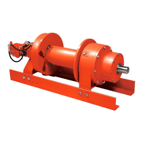
Dover TWG RUFNEK 50P Operating instructions

http://www.twg.com
SEL-0143-000
REV 0 JUNE 2014
RUFNEK 50P
Service/Repair Manual
DESIGN SERIES 001
TABLE OF CONTENTS
INTRODUCTION AND THEORY OF OPERATION.........................................................................................4
MAINTENANCE AND SERVICE....................................................................................................................5
RECOMMENDED OILS ................................................................................................................................6
OIL CHANGE...............................................................................................................................................7
DISASSEMBLY............................................................................................................................................8
MOTOR
DISASSEMBLY..................................................................................................................................8
BRAKE
SECTION
DISASSEMBLY...................................................................................................................9
DRUM
SECTION
DISASSEMBLY..................................................................................................................10
CLUTCH
INSPECTION .................................................................................................................................11
GEAR
SECTION
DISASSEMBLY...................................................................................................................12
INPUT
PLANET
SET
DISASSEMBLY.............................................................................................................13
SECONDARY
PLANET
SET
DISASSEMBLY ......................................................E
RROR
!
B
OOKMARK NOT DEFINED
.
OUTPUT
PLANET
SET
DISASSEMBLY..........................................................................................................14
ASSEMBLY................................................................................................................................................15
OUTPUT
PLANET
SET
ASSEMBLY................................................................................................................15
SECONDARY
PLANET
SET
ASSEMBLY.............................................................E
RROR
!
B
OOKMARK NOT DEFINED
.
INPUT
PLANET
SET
DISASSEMBLY.............................................................................................................16
GEAR
END
ASSEMBLY .................................................................................................................................17
DRUM
SECTION
ASSEMBLY........................................................................................................................18
BRAKE
SECTION
ASSEMBLY.......................................................................................................................20
MOTOR
ASSEMBLY......................................................................................................................................22
TROUBLESHOOTING ................................................................................................................................23
TORQUE SPECIFICATIONS CHART...........................................................................................................24
BILL OF MATERIAL...................................................................................................................................25
CROSS SECTIONAL ASSEMBLY DRAWING...............................................................................................28
EXPLODED ASSEMBLY DRAWING............................................................................................................29
INSTALLATION DRAWING.......................................................................................................................30

2
FAILURE TO HEED THE FOLLOWING WARNINGS MAY
RESULT IN SERIOUS INJURY OR DEATH!
The safety of the winch operator and ground personnel should always be of great concern, and all
necessary precautions to insure their safety must be taken. The primary mover and the winch must
be operated with care and concern for the equipment and the environment. Additionally, a
thorough knowledge of the equipment and its performance capabilities must be understood. These
general safety guidelines are offered, however local rules and regulations or national standards may
also apply. Recommended references are, but not limited to, ANSI B30, OSHA 1910, AWS D 14.3,
and SAE J706.
Additional information can be found at http://www.team-twg.com/TulsaWinch/
Mounting:
Winch mounting must be secure and able to withstand the applied loads.
The stability of the mounting system must be approved by a qualified person.
All welding should also be done by a qualified person.
Winch mount must be flat so as not to induce binding.
The flatness must not exceed 1/16 inch across the mounting surface of the winch itself.
Guards must be placed on all open drives in the case of mechanical winches.
Insure that all PTO’s and drivelines are sized appropriately for the winch manufactures speed and
torque specifications.
Indicates an imminently hazardous situation
which, if not avoided, will result in death or serious
injury.
Indicates a potentially hazardous situation which,
if not avoided, could result in death or serious
injury.
Indicates a potentially hazardous situation which,
if not avoided, may result in minor or moderate
injury or property damage.
Indicates information or a company policy that
relates directly or indirectly to the safety of
personnel or protection of property.

3
Operator:
Must read and understand the operating and service manual.
Both the SERVICE MANUAL and OPERATING AND MAINTENANCE MANUAL are
available online at http://www.team-twg.com/TulsaWinch/
Must never lift or move people with this winch.
This winch is not designed or intended for any use that involves moving people.
Must stay clear of the load at all times.
Ground personnel should remain a safe distance from the load and winch cable- at least 1 ½
times the length of cable measured from the winch to the load.
Must stay clear of the cable at all times.
A broken cable can cause serious injury or death.
Must avoid shock loads.
Shock loads can impose a strain on the winch that can be many times the design rating.
Must be aware of the fleet angle of the winch.
All loads should only be pulled with the load line perpendicular to the drum shaft; this is to
avoid excessive stresses on the winch and will help prevent the cable from building on one
side of the drum flange.
Must wear personnel protective equipment (PPE) if required.
Check the local, state and federal regulations for compliance.
Must insure that the drum clutch is fully engaged before hoisting.
A visual inspection of the drum clutch engagement is required before each winching
operation.
Must rig all loads secure before winching.
Pull the load line taut and inspect the condition of load for stability.
Must inspect the drum brake.
The drum brake is not a load holding device. It is designed to prevent over spooling of the
drum, causing the cable to bird nest on the drum. Inspect the brake band for worn lining
and the actuation method.
Must inspect the load control brake.
This winch is equipped with a form of dynamic braking. The worm brake is adjustable for
pay-out load control. Before a load is handled the load should be pulled tight and stopped to
check this brake.
Operation:
All winch controls must be well marked for function to avoid confusion.
Insure that the PTO is disengaged when the winch is not in use.
All winch controls must be located to provide the operator with a clear view of the load.
The clutch must be inspected daily for proper operation.
The winch cable should be inspected daily for serviceability.
A minimum of five wraps of tightly wound cable must remain on the drum.
4
INTRODUCTION AND THEORY OF OPERATION
The Rufnek series planetary winch is designed to use a high-speed gear motor, driving
through a multiple disc brake, through three planet sets to the cable drum.
The multiple-disc brake is spring applied and hydraulically released through a port in the brake
housing. During inhaul, the brake is not released since the load is driven through the one-way cam
clutch, bypassing the brake. When the load comes to a stop, the cam clutch locks up and the load
is prevented from moving by the brake.
The brake and brake valve receives its signal any time the winch is in pay out. With the
brake fully open at about 340 PSI the brake valve will open and dynamically control the lowering of
the load.
ASSEMBLY NUMBER EXPLANATION
This manual is for design series 001. In the case of a major design change implementation, a new
design series designation number will be issued for the winch. A new manual will also be created for that
specific design series.
MODEL CODE
82438 001
A
SSEMBLY # SERIES
DESIGN
Gear Type
W=Worm
P=Planetary
Drive Type
H=Hydraulic
M=Mechanical
Gearbox Position
L=Left
R=Right
(viewed from rear of truck)
Input Shaft Location
F=Front
R=Rea
r
X=Does not apply
(viewed from rear of truck)
Cable Spooling
O=Over Drum
U=Under Drum
(viewed from rear of truck)
Clutch Device
M=Mechanical
A
=Ai
r
Motor Type
1. Single Speed Gear Moto
r
2. Two Speed Gear Moto
r
3. Single Speed Geroler Moto
r
4. Two Speed Geroler Moto
r
5. Piston
6. Vane
X. No Moto
r
RN50 P
HRXOA2

5
MAINTENANCE AND SERVICE
For safe and consistent operation of TULSA WINCH hoists, swing drives, and winches, a regular
program of preventive maintenance is strongly recommended. Regular oil changes with the correct
oil for the ambient temperature conditions and an annual inspection of the wear components will
help ensure a long life for your planetary geared products.
Tulsa Rufnek series planetary winches, like any other piece of machinery, need to be periodically
serviced and well maintained to insure proper operation.
Good maintenance consists of four steps.
1. A daily inspection to insure that there are no oil leaks present and that all mounting bolts
and other fasteners are tight, and that the wire rope is in good condition.
2. Changing the oil in both the gearbox and the brake section.
(Severity of use will determine
the need for oil changes but it should be checked at a minimum of every 500 hours. Factors
such as extremely dirty conditions or widely varying temperature changes may dictate even
more frequent servicing)
.
3. Lubing drum bushings and sliding clutch with grease thru grease fittings located on drum
barrel and clutch.
4. Complete teardowns and component inspections.
(Again, severity and frequency of use will
determine how often this should be done)
. If the equipment that this winch is mounted to is
subject to standards for this type of inspection, then those standards must be followed. If
oil changes reveal significant metallic particles then a teardown and inspection must be
made to determine the source of wear.
OIL LEVEL MAINTENANCE
Tulsa Winch recommends that the oil level in the gearbox and brake housing be checked and
adjusted as part of the pre-use inspection. If the oil level drops frequently or oil leakage is
detected during an inspection, maintenance should be performed to correct any problems.

6
RECOMMENDED OILS
FOR STANDARD TEMP APPLICATIONS -10˚F THRU 150˚F (-23˚C THRU 66˚C) oil temp.
*Gearbox oil (GL-5):
Any GL-5 75W-90 Oil
FOR LOW TEMP APPLICATIONS -40˚F THRU 180˚F (-40˚C THRU 82˚C) oil temp.
*Gearbox oil (GL-5): Shipped from the factory filled with Mobilube SHC SAE 75W-90
synthetic gear oil
*All gearbox oils must meet MIL-PRF2105 & GL-5 specifications.
OIL CAPACITY
GEARBOX 7 QTS
BRAKE .25 QTS
Do not use EP type gear lubes in the brake section of this winch. EP lubes
may prevent the clutch from locking up, which, in turn causes the load to fall,
resulting in property damage, personal injury, or death.
The hydraulic system should use only high quality hydraulic fluid from reputable suppliers. These
oils should contain additives to prevent foaming and oxidation in the system. All hoist hydraulic
systems should be equipped with a return line filter capable of filtering 10 micron particles from the
system.

7
FIG 1
FIG 2
OIL CHANGE
The oil is drained by removing the drain plugs (81 & 86) located at bottom of gear housing (60)
(Figure 1) and bottom of brake cover (2) (Figure 2).
Then remove the fill plugs (81, 74 & 75) located at the top of the gear housing (3) and the top of
the brake cover (2). Inspect the oil for signs of metallic particles and/or burning and dispose of in a
proper manner. Then re-install the drain plugs.
Fill the brake end with 75W-90 (1/4 quart), then fill the gear end 75W-90 oil (7 quarts) and replace
both of the fill plugs.
See Oil Chart Pg. 6 this manual for recommended oil type and grade for your
application.

8
DISASSEMBLY
MOTOR DISASSEMBLY
1. Drain the oil from the brake assembly by removing the plug (81) from the bottom of the brake
cover (2).
2. Remove hoses (42, 45, 58, 79, & 80).
3. Remove the counterbalance block (32) and the manifold block (56), from the motor (1) by
removing the four cap screws (88).
4. Remove the motor (1) from the winch by removing four capscrews (88).
5. Remove the counterbalance valve (50) from the counterbalance block (32) and inspect the
metering hole to make sure it is not obstructed. Also, inspect the o-rings on the valve to insure
that they are not flat or cut. Replace if necessary.
6. Motors and counterbalance valves are not serviceable in the field. Return them to an authorized
dealer for service.
7. Inspect o-rings (98) & (49) for damage.

9
BRAKE SECTION DISASSEMBLY
1. Evenly remove the four capscrews (3) that hold the brake cover (2) in place. Spring pressure
will raise the cover up as the cap screws are loosened. Carefully remove the cover (2) from the
brake housing (20). Inspect the o-ring (6) for damage.
2. Remove the springs (7) from the piston (5) and check the free height. Each spring should
measure at least 1.094 inches with no force on them.
3. Remove the piston (5) by installing two pieces of 3/8”-16NC all thread into the two holes in the
top of the piston and run in evenly until the piston is clear of the housing. An alternative
method of removing the piston is to use shop air to slowly pressurize the brake port to remove
the piston from the brake housing (20).
4. Inspect the o-rings (8, 10) and back up rings (9, 11) on the piston. Grasp the brake
driver/clutch assembly (assembled items 14, 17, 18, 19, 52) and remove it from the brake
housing.
5. Remove the stator plates (12) and friction discs (13) from the brake housing and check them for
excessive wear, and replace if necessary. Be sure to check the top stator plate for scoring
caused by the removal of the piston and polish if needed. Friction discs should measure no less
than .055-in. thickness and stator plates should measure no less than .068-in thick.
6. To disassemble the brake driver/clutch assembly, remove the retaining ring (17) from either end
of the driver. Then, remove the brake driver (14) and bearing (52) from the input driver (19).
Next, remove the sprag clutch (18). Finally, remove the retaining ring (17) from the other end
of the driver, then remove the second bearing (52) from the input driver.
Notice the direction of lock-up
on the clutch (18) for re-assembly.
7. Remove the bearing housing (16) and inspect the bearing (15).
8. If the bushing or seal in the brake housing needs to be replaced, follow the drum section
disassembly and reassembly sections of this manual prior to reassembly of the brake.

10
DRUM SECTION DISASSEMBLY
1. To remove the drum, first disconnect the cable from the U-bolt (35) and lay aside. If removing the
drum from the motor end with the motor and brake disassembled, first remove the cotter keys (93)
and clevis pins (100) connecting the yoke (87) to the bracket (101) and air cylinder (67).
You may need to remove the airlines, mark them for re-assembly.
2. Support the weight of the drum with a hoist. Remove the four cap screws (61) along with the
nuts and washers (62, 63) on the bottom of the brake housing (20). Disconnect the airline
running from the air cylinder (67) to the brake housing (20). Remove the brake housing by
sliding the housing off of the output shaft (40-9). At this time you will need to remove the two
cap screws (70), nuts and washers (71 & 72) from the frames (64 & 65). Do not remove the air
cylinder (68) yet. Disconnect the airline from the backside of the brake housing (20) that goes
to the brake band air cylinder. You can now remove the brake band assembly (66). Note which
frame the mounting bolts are on for re-assembly. Inspect and replace if needed.
3. Remove the outer thrust collar (105) by loosening three set screws (89).
4. Remove the yoke (87) and sliding clutch (27). Next remove the coupler (30) from the output
shaft (40-9). Remove the two keys (94) and the inner thrust collar (24). Remove the drum
using a hoist. Inspect the bushings (31) in both ends of the drum.
You should inspect the bushing and seal (38, 25) that are located
in the end of the brake housing
5. Inspect the drum clutch (28) by removing the six capscrews (33) from the drum. Replace the
clutch if necessary (See Clutch Inspection on page 11). Torque the capscrews to the specified
torque upon re-assembly. (See torque specifications chart on page 25 of this manual.)
6. Inspect the grease tube (115) and fittings (113, 114) inside the drum for wear or damage,
replace if needed.

11
CLUTCH INSPECTION
GOOD
This picture illustrates a sliding and
drum clutch with the proper reverse
draft and minimum edge wear.
BAD
The reverse draft ensures the clutch
stays engaged during pay-in.
Without the correct draft, the clutch
could dis-engage unpredictably.
CLUTCH REPLACEMENT CRITERIA
If 1/4 of the surface of the face on the
sliding clutch or drum clutch is rounded
or has no reverse draft, the sliding clutch
and/or drum clutch must be replaced.

12
GEAR SECTION DISASSEMBLY
1. Drain the oil by removing the plug (86) located on the bottom of the gear housing (60).
2. To disassemble the gear section, remove the Intelliguard™ (39) from the end cover (55) by
removing three capscrews (44). Inspect the gear teeth on the Intelliguard™ (39) for wear. The
Intelliguard™ system is not serviceable in the field. Return to an authorized dealer for service.
3. Remove the eight capscrews (21) from the end cover (55), and remove the end cover.
4. Inspect the o-rings (36 & 59) and replace if necessary.
5. Remove the input gear set (41), along with the inner and outer thrust washers (43). Inspect
parts and replace if necessary.
6. Remove the output sun gear (47). Carefully remove the output gear set and output shaft
assembly (40) from the gear housing.
7. Remove and inspect the thrust washer (37).

13
INPUT PLANET SET DISASSEMBLY
1. Remove the retaining rings (41-5) from the planet pins (41-6).
2. Remove the pins from the carrier (41-1) by carefully tapping them out.
3. Remove the planet gears (41-3), thrust washers (41-4), and bearings (41-2) from the carrier
(42-1).
4. With the planet gears (41-3) out, remove the plate (41-7).
5. Inspect the parts for wear or damage and replace if necessary.

14
OUTPUT PLANET SET DISASSEMBLY
1. Remove the retaining rings (40-4) from the planet pins (40-3).
2. Remove the pins from the carrier (40-1) by carefully tapping them out.
3. Remove the planet gears (40-2), thrust washers (40-8), and bearings (40-6) from the carrier
(40-1).
4. Inspect the parts for wear or damage and replace if necessary.
5. With the planet gears (40-2) out, remove the plate (40-5) and the retaining ring (40-7).
Remove the output shaft (40-9) from the carrier and inspect parts for wear or damage.

15
ASSEMBLY
OUTPUT PLANET SET ASSEMBLY
1. Insert the output shaft (40-9) into the carrier (40-1) and install the retaining ring (40-7).
2. Next insert the thrust plate (40-5) into the carrier along with the gears (40-2), bearings (40-6),
and washers (40-8).
3. Be careful to line up the thrust washers (40-8) and bearings (40-6) with the planet pins (40-3),
press the pin into the carrier (40-1).
If the pins are not lined up properly, the thrust washer can be
shattered during the pressing operation.
4. Replace the retaining rings (40-4).

16
INPUT PLANET SET DISASSEMBLY
1. Insert the thrust plate (41-7) into the carrier (41-1) along with the gears (41-3), bearings (41-
2), and thrust washers (41-4).
2. Being careful to line up the thrust washers (41-4) and bearings (41-2) with the planet pins (41-
6), press the pins into the carrier (42-1).
If the pins are not lined up properly, the thrust washer can be
shattered during the pressing operation.
3. Replace the retaining rings (41-5).

17
GEAR END ASSEMBLY
1. Bolt the gear-housing (60) loosely into both frames (64, 65) using four capscrews, washers, and
nuts (61, 62, & 63).
2.
When reassembling, apply grease to parts such as the thrust washers, o-rings, and seals. Slide
the thrust washer (37) onto the output shaft (40-9). Next, install the output gear set (40). Push
the gear set and shaft back into the housing until it stops against the thrust washer (37).
Make sure to line up all three planet gears in the output gear with
the gear housing as it starts into the housing.
3. Install the output sun gear (47) into the output gear set (40).
4. Install the thrust washer (43) onto the input gear set (41). Insert the input gear set (41) into the
gear housing (60), making sure it is against the output gear set (40) and engaged with the
output sun gear (47).
5. Put the outer thrust washer (43) in place and slide the input shaft (39-2) all the way through the
output shaft (40-9). Let the input shaft protrude out on the gear end so that all of the spline is
showing. It will not work if installed backwards.
6. Put the cover (55) on and secure it with eight capscrews (21), being careful not to damage the
o-ring (59). Install the Intelliguard™ (39) into the end cover (55), again making sure not to
damage the o-ring (36), and secure it with three capscrews (44).
Make sure the input shaft engages the gear in the Intelliguard™
correctly.

18
DRUM SECTION ASSEMBLY
1. After inspecting and replacing the necessary parts, such as the drum bushings (31), install the
bushing (4) onto the output shaft (40-9).
2. Install the drum (34) onto the output shaft (40-9). This part is very heavy and you will need the
assistance of a hoist. With the weight of the drum supported, install the brake band assembly
(66) and the capscrews (70), nuts (71), and washers (72).
You may need to lower the drum to align the holes in the brake
band with the holes in the frame.
3. Install the brake band air cylinder (68) making sure the rod of the air cylinder is going through
the bracket on the brake band (66). Secure it to the bracket with the clevis pin (99) and cotter
pin (100). Tighten the adjusting nut on the air cylinder shaft until there is no space between the
drum (34) and the brake band (66). Then, tighten the jam nut to secure the adjusting nut.
The brake band may need to be readjusted once it’s in the field.
4. Install the bushing (4) onto the output shaft (40-9). Install the inner thrust collar (24) making
sure the half-moon slots are lined up with the key slots in the output shaft (40-9). Tap the two
keys (94) into their slots in the output shaft.
5. If necessary, install the new drum clutch (28) using six capscrews (33). Torque to specified
torque (see page 25 of this manual). Then, align the coupler (30) with the keys (94) and slide it
onto the output shaft (40-9). Install the sliding clutch (27) onto the coupler (30). Then install
the yoke (87) onto the sliding clutch (27).
6. Install the outer thrust collar (105), aligning the half-moon slots with the keys (94). Tightly hold
the thrust collar (105) against the keys and lock down the three set screws (89).
7. Install the oil seal (25) onto the output shaft (40-9).
8. Slide the brake housing (20) onto the output shaft (40-9).
9. Bolt the brake housing (20) loosely into both frames (64, 65) using four capscrews, washers, and
nuts (61, 62, & 63). Lower the drum so the weight of the drum is supported by both the brake
and gear housings. The air line from the brake band air cylinder can be attached at this time.
10. Disengage the sliding clutch (27) so you can turn the drum freely and tighten all bolts
throughout the frames to the proper torque specification (see page 25 of this manual).
11. Turn the drum to make sure it is not binding.
12. Install the air cylinder (67) and the air cylinder cover (91) to the brake housing with four
capscrews (69) and spacers (97).
13. Install the bracket (101) to the brake housing using four capscrews (90).

19
DRUM SECTION ASSEMBLY CONT.
14. Attach the yoke (87) by installing clevis pins (93) into the bracket (101) and the air cylinder
clevis (92). Install the cotter pins (100) into the clevis pins (93) in order to secure their
positions.
15. Connect shop air to the cylinder and apply air in both directions. With the clutch fully engaged
(air applied), there should be slight movement on the sliding clutch in both directions. Adjust
clevis (92) and air cylinder jam nut accordingly.

20
FIG 3
BRAKE SECTION ASSEMBLY
1. Re-assemble the driver/clutch assembly (14, 17,
18, 19, 52) making sure the clutch is installed
properly and checking to make sure the cam
clutch is free turning in the pay in direction.
2. Measure the distance from the face of the brake
housing to the end of the shaft as shown
(Figure 3).
3. If needed, add shims (111, 112) inside the
input driver (54) next to the end of the input
shaft (39-2) to achieve dimension noted.
If measurement is
between 1.547 &
1.622, use Item 111 (max of 3 shims). If
measurement is between 1.622 & 1.727, use
Item 112 (max of 2 shims).
4. Install the bearing housing assembly that contains parts 15, 16, and 22 into the brake housing.
5. Install the driver/clutch assembly onto the input shaft (39-2).
6. Install the stator plates (12) and friction discs (13) starting with a stator plate and alternating
between friction discs and stator plates until seven stator plates and six friction discs are used.
Dip friction discs in lightweight Non-EP oil before installation.
7. Install the piston (5) into the brake housing (20) and gently tap it down until it is seated making
sure not to damage the o-rings (8, 10) or back-up rings (9, 11).
8. Install the springs (7) into the spring pockets. If working in a horizontal position, coat the
bottom of each spring with chassis lube to keep it in position.
9. Install the cover (2) onto the brake housing (20) using four capscrews (3) being careful not to
damage the o-ring (6). Draw the cover down evenly, alternating between opposite hex bolts.
Make sure that the cover is aligned properly with the brake housing in order to orient the motor
as it should be.
Table of contents
Other Dover Winch manuals

Dover
Dover TWG design 004 Series User manual

Dover
Dover Pull MASTER H8 Technical reference manual

Dover
Dover TWG TULSA WINCH 1200W User manual

Dover
Dover TWG TULSA WINCH 707W User manual

Dover
Dover TWG LANTEC 200 Manual

Dover
Dover TWG Tulsa RUFNEK 80 DESIGN 001 Series User manual

Dover
Dover TWG Tulsa 12-SLLRO Series Owner's manual

Dover
Dover TWG TULSA WINCH 506W User manual

Dover
Dover TWG Tulsa RUFNEK Series User manual

Dover
Dover TWG Tulsa 18G Operating and installation instructions