Lindab WH45P User manual

English
Installation type with re resistance class
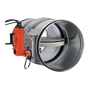
PATENTED FIRE DAMPER
CIRCULAR SERIES WH45P - 500 Pa / 300 Pa
Cert. N° 1812-CPR-1107
Technical Manual
WH45P
WH45P
lindab | we simplify construction
Technical Manual
Installation type with re resistance class
English
FIRE DAMPER
CIRCULAR SERIES WH45P - 500 Pa
Cert. N° 1812-CPR-1107

This is a 42 page manual.

TABLE OF CONTENTS
WH45P
3/42
rev 20-10
1. Overview . . . . . . . . . . . . . . . . . . . . . . . . . . . . . . . . . . . . . . . . . . . . . . . . . . p.4
1.1. Description � � � � � � � � � � � � � � � � � � � � � � � � � � � � � � � � � � � � � � � � � � � � � � � � � � � � � p�4
1.2. General characteristics � � � � � � � � � � � � � � � � � � � � � � � � � � � � � � � � � � � � � � � � � � � � � � � � p�4
1.3. European Standards applied � � � � � � � � � � � � � � � � � � � � � � � � � � � � � � � � � � � � � � � � � � � � � p�4
1.4. Certications and approvals � � � � � � � � � � � � � � � � � � � � � � � � � � � � � � � � � � � � � � � � � � � � � p�4
1.5. Components � � � � � � � � � � � � � � � � � � � � � � � � � � � � � � � � � � � � � � � � � � � � � � � � � � � � � p�4
1.6. Available dimensions � � � � � � � � � � � � � � � � � � � � � � � � � � � � � � � � � � � � � � � � � � � � � � � � � p�4
1.7. Performances � � � � � � � � � � � � � � � � � � � � � � � � � � � � � � � � � � � � � � � � � � � � � � � � � � � � p�5
1.8. Fire resistance classication according to EN 13501-3-2009 � � � � � � � � � � � � � � � � � � � � � � � � � � � � � � � p�5
1.9. Mechanism type � � � � � � � � � � � � � � � � � � � � � � � � � � � � � � � � � � � � � � � � � � � � � � � � � � � p�7
2. Technical data . . . . . . . . . . . . . . . . . . . . . . . . . . . . . . . . . . . . . . . . . . . . . . . p.9
2.1. Dimension � � � � � � � � � � � � � � � � � � � � � � � � � � � � � � � � � � � � � � � � � � � � � � � � � � � � � � p�9
2.2. Weights � � � � � � � � � � � � � � � � � � � � � � � � � � � � � � � � � � � � � � � � � � � � � � � � � � � � � � � p�9
3. Installation . . . . . . . . . . . . . . . . . . . . . . . . . . . . . . . . . . . . . . . . . . . . . . . . p.10
3.1. Intended use � � � � � � � � � � � � � � � � � � � � � � � � � � � � � � � � � � � � � � � � � � � � � � � � � � � � p�10
3.2. Not allowed uses � � � � � � � � � � � � � � � � � � � � � � � � � � � � � � � � � � � � � � � � � � � � � � � � � � p�10
3.3. Positioning brackets before xing � � � � � � � � � � � � � � � � � � � � � � � � � � � � � � � � � � � � � � � � � � p�10
3.4. Blade rotation axis positioning � � � � � � � � � � � � � � � � � � � � � � � � � � � � � � � � � � � � � � � � � � � p�10
3.5. Installation of exible connectors in order to balance out the ventilation ducts expansion � � � � � � � � � � � � � � � p�10
3.6. Transfer Application (application not connected to air ducts on one or both sides) � � � � � � � � � � � � � � � � � � p�12
3.7. Minimum distances � � � � � � � � � � � � � � � � � � � � � � � � � � � � � � � � � � � � � � � � � � � � � � � � � p�14
3.8. Construction supports characteristics � � � � � � � � � � � � � � � � � � � � � � � � � � � � � � � � � � � � � � � � p�16
3.9. Installations within vertical rigid wall � � � � � � � � � � � � � � � � � � � � � � � � � � � � � � � � � � � � � � � � p�19
3.10. Installations within vertical light wall (plasterboard) � � � � � � � � � � � � � � � � � � � � � � � � � � � � � � � � � p�21
3.11. Installation within vertical light wall (gypsum blocks wall) � � � � � � � � � � � � � � � � � � � � � � � � � � � � � � p�22
3.12. Installations within oor � � � � � � � � � � � � � � � � � � � � � � � � � � � � � � � � � � � � � � � � � � � � � � p�23
3.13. Installations within vertical wall with Fire Batt (Weichschott) sealing � � � � � � � � � � � � � � � � � � � � � � � � � p�24
3.14. Installation within oor with Fire Batt (Weichschott) sealing � � � � � � � � � � � � � � � � � � � � � � � � � � � � � p�25
4. Electrical connections . . . . . . . . . . . . . . . . . . . . . . . . . . . . . . . . . . . . . . . . . . p.26
4.1. Electrical wiring � � � � � � � � � � � � � � � � � � � � � � � � � � � � � � � � � � � � � � � � � � � � � � � � � � p�26
4.2. Electrical specications � � � � � � � � � � � � � � � � � � � � � � � � � � � � � � � � � � � � � � � � � � � � � � � p�27
5. Maintenance and inspections . . . . . . . . . . . . . . . . . . . . . . . . . . . . . . . . . . . . . . p.28
5.1. Periodic inspection and cleaning � � � � � � � � � � � � � � � � � � � � � � � � � � � � � � � � � � � � � � � � � � p�28
5.2. Repair � � � � � � � � � � � � � � � � � � � � � � � � � � � � � � � � � � � � � � � � � � � � � � � � � � � � � � � p�28
5.3. Disposal � � � � � � � � � � � � � � � � � � � � � � � � � � � � � � � � � � � � � � � � � � � � � � � � � � � � � � p�28
6. Selection . . . . . . . . . . . . . . . . . . . . . . . . . . . . . . . . . . . . . . . . . . . . . . . . . p.29
6.1. Air ow rates in relation to the diameter � � � � � � � � � � � � � � � � � � � � � � � � � � � � � � � � � � � � � � � p�29
6.2. Air ow rates as a function of the pressure drop � � � � � � � � � � � � � � � � � � � � � � � � � � � � � � � � � � � p�29
6.3. Air ow rates as a function of generated sound levels � � � � � � � � � � � � � � � � � � � � � � � � � � � � � � � � p�29
6.4. Pressure drop and sound level graph Ø 200-560 � � � � � � � � � � � � � � � � � � � � � � � � � � � � � � � � � � � p�30
6.5. Pressure drop and sound level graph Ø 450-800 � � � � � � � � � � � � � � � � � � � � � � � � � � � � � � � � � � � p�31
6.6. Sound spectrum table � � � � � � � � � � � � � � � � � � � � � � � � � � � � � � � � � � � � � � � � � � � � � � � p�31
7. Accessories and spare parts . . . . . . . . . . . . . . . . . . . . . . . . . . . . . . . . . . . . . . . p.32
8. How to order . . . . . . . . . . . . . . . . . . . . . . . . . . . . . . . . . . . . . . . . . . . . . . . p.35
8.1. Motorized re dampers � � � � � � � � � � � � � � � � � � � � � � � � � � � � � � � � � � � � � � � � � � � � � � � p�35
8.2. Fire damper with manual control � � � � � � � � � � � � � � � � � � � � � � � � � � � � � � � � � � � � � � � � � � p�35
8.3. Electric motor driven actuators � � � � � � � � � � � � � � � � � � � � � � � � � � � � � � � � � � � � � � � � � � � p�36
9. Specication Text . . . . . . . . . . . . . . . . . . . . . . . . . . . . . . . . . . . . . . . . . . . . p.37
9.1. Series WH45P circular re damper � � � � � � � � � � � � � � � � � � � � � � � � � � � � � � � � � � � � � � � � � � p�37
10. Revision Index . . . . . . . . . . . . . . . . . . . . . . . . . . . . . . . . . . . . . . . . . . . . . . p.38
WH45P
3
We reserve the right to make changes without prior notice
OVERVIEW
WH45P
4/42 rev 20-10
1. OVERVIEW
1.1. Description
Fire dampers WH45P are devices for use in heating, venti-
lation and air-conditioning (HVAC) systems at re bounda-
ries to maintain compartmentation and protect means of
escape in case of re. They satisfy integrity, insulation and
smoke leakage criteria for the declared time of re resistan-
ce.
Tested and classed in accordance with EN 1366-2 and EN
13501-3 regulations with 500 Pa depression (300 Pa for in-
stallations with Weichschott sealing).
Studied and optimized for medium and big diameter ducts
focusing on aeraulic and acoustical performance.
1.2. General characteristics
• Casing made from galvanized carbon steel.
• Optional duct connection gaskets: order accessory
CM-WH-GUARNRACC[Ø].
• Intumescent sealing gasket.
• Opening/closing mechanism with IP42 protection box
(IP54 for motorized version).
• 40 mm thick closing blade made with refractory material.
• Lip seal on blade border for cold smoke seal.
• Internal intumescent gasket for hot smoke seal.
1.3. European Standards applied
CE certication EN 15650
Test EN 1366-2
Classication EN 13501-3
Thermal fuse reliability ISO 10294-4
Air tightness EN 1751
Resistance to corrosive environments EN 60068-2-52
1.4. Certications and approvals
CE Certicate of Constancy of Performance n° 1812-CPR-1107 Efectis
RISE Approval (Sweden) n° SC0194-16 RISE
1.5. Components
1. Casing made from galvanized carbon steel.
2. Mineral ber gasket between the 2 re damper casings.
3. Intumescent graphite gasket on inside of casing for the hot seal
of the blade once closed
4. Damper blade made from refractoring material
5. Gasket to prevent air losses on the mechanism plate.
6. Blade rotation axis, pivots housing.
7. Blade drive with crank and slotted link mechanism
8. Protection box
9. Manual closing device (Test button)
10. Temperature controlled closing device (thermal fuse)
1.6. Available dimensions
Ø mm 200 250 300 315 355 400 450 500 560 600 630 710 800
WH45P
4We reserve the right to make changes without prior notice
OVERVIEW
WH45P
5/42
rev 20-10
1.7. Performances
Performance Reference standard Class
Thermal fuse testing ISO 10294-4 Compliant
Open and Close cycle reliability EN 15650 Compliant
Resistance to corrosion in humid and saline environments EN 60068-2-52 Degree of severity 2
Casing tightness EN 1751 Class C(1)
Blade seal EN 1751 Class 2 minimum
(1) Casing leakage class C for diameter bigger than 315 mm as per EN 1751.
Casing leakage class B minimum for diameter less than or equal to 315 mm as per EN 1751 (class C on request).
1.8. Fire resistance classication according to EN 13501-3-2009
EI 180 S
(500 Pa) EI 120 S
(500 Pa) EI 90 S
(500 Pa) EI 60 S
(500 Pa) EI 30 S
(500 Pa)
Rigid wall
EI 90 S Installation within vertical rigid wall p.19
Wall minimum thickness 100 mm
Wall minimum density 500 kg/m³
Plasterboard and rock wool 100 kg/m³ sealing
ve (i↔o)
D - - Ø
min 200
max 800
Ø
min 200
max 800
Ø
min 200
max 800
EI 120 S Installation within vertical rigid wall p.19
Wall minimum thickness 100 mm
Wall minimum density 500 kg/m³
Mortar or plaster putty sealing
ve (i↔o)
W - Ø
min 200
max 800
Ø
min 200
max 800
Ø
min 200
max 800
Ø
min 200
max 800
EI 180 S Installation within vertical rigid wall p.19
Wall minimum thickness 150 mm
Wall minimum density 500 kg/m³
Mortar sealing
ve (i↔o)
WØ
min 200
max 800
Ø
min 200
max 800
Ø
min 200
max 800
Ø
min 200
max 800
Ø
min 200
max 800
Flexible wall
EI 90 S Installation within vertical light wall (plasterboard) p.21
Wall minimum thickness 100 mm
Wall rock wool density up to 100 kg/m³ (optional)
Plasterboard and rock wool 100 kg/m³ sealing
ve (i↔o)
D - - Ø
min 200
max 800
Ø
min 200
max 800
Ø
min 200
max 800
EI 120 S Installation within vertical light wall (plasterboard) p.21
Wall minimum thickness 100 mm
Wall rock wool density up to 100 kg/m³ (optional)
Mortar or plaster putty sealing
ve (i↔o)
W - Ø
min 200
max 800
Ø
min 200
max 800
Ø
min 200
max 800
Ø
min 200
max 800
EI 90 S Installation within vertical light wall (gypsum blocks wall) p.22
Wall minimum thickness 70 mm
Wall minimum density 995 kg/m³
Plaster putty sealing
ve (i↔o)
W - - Ø
min 200
max 800
Ø
min 200
max 800
Ø
min 200
max 800
EI 120 S Installation within vertical light wall (gypsum blocks wall) p.22
Wall minimum thickness 100 mm
Wall minimum density 995 kg/m³
Plaster putty sealing
ve (i↔o)
W - Ø
min 200
max 800
Ø
min 200
max 800
Ø
min 200
max 800
Ø
min 200
max 800
WH45P
5
We reserve the right to make changes without prior notice
OVERVIEW
WH45P
6/42 rev 20-10
EI 180 S
(500 Pa) EI 120 S
(500 Pa) EI 90 S
(500 Pa) EI 60 S
(500 Pa) EI 30 S
(500 Pa)
Floor
EI 90 S Installation within oor p.23
Floor minimum thickness 100 mm
Floor minimum density 650 kg/m³
Mortar sealing
ho (i↔o)
W - - Ø
min 200
max 800
Ø
min 200
max 800
Ø
min 200
max 800
EI 120 S Installation within oor p.23
Floor minimum thickness 150 mm
Floor minimum density 650 kg/m³
Mortar sealing
ho (i↔o)
W - Ø
min 200
max 800
Ø
min 200
max 800
Ø
min 200
max 800
Ø
min 200
max 800
EI 180 S Installation within oor p.23
Floor minimum thickness 150 mm
Floor minimum density 2200 kg/m³
Mortar sealing
ho (i↔o)
WØ
min 200
max 800
Ø
min 200
max 800
Ø
min 200
max 800
Ø
min 200
max 800
Ø
min 200
max 800
Ø is the minimum and maximum nominal diameter of re dampers in mm
ve Vertical installation
ho Horizontal installation
(i↔o) Origin of re irrelevant
Pa Pascal of depression
E Integrity
I Thermal insulation
S Smoke seal
W Wet method sealing
D Dry method sealing
Cert. N° 1812-CPR-1107
1.8.1. Fire Batt (Weichschott) sealings
EI 120 S
(300 Pa) EI 90 S
(300 Pa) EI 60 S
(300 Pa) EI 30 S
(300 Pa)
Rigid wall
EI 120 S Installation within vertical rigid wall with Fire Batt (Weichschott) sealing p.24
Wall minimum thickness 100 mm
Wall rock wool minimum density 500 kg/m³
Rock wool 140 kg/m³ and endothermic varnish sealing
ve (i↔o)
WØ
min 200
max 800
Ø
min 200
max 800
Ø
min 200
max 800
Ø
min 200
max 800
Minimum distance allowed between 2 dampers 200 mm 50 mm 50 mm 50 mm
Flexible wall
EI 120 S Installation within vertical light wall (plasterboard) with Fire Batt (Weichschott) sealing p.24
Wall minimum thickness 100 mm
Wall rock wool density up to 100 kg/m³ (optional)
Rock wool density 140 kg/m³ and endothermic varnish sealing
ve (i↔o)
WØ
min 200
max 800
Ø
min 200
max 800
Ø
min 200
max 800
Ø
min 200
max 800
Minimum distance allowed between 2 dampers 200 mm 50 mm 50 mm 50 mm
EI 120 S Installation within vertical light wall (gypsum blocks wall) with Fire Batt (Weichschott) sealing p.24
Wall minimum thickness 100 mm
Wall minimum density 995 kg/m³
Rock wool 140 kg/m³ and endothermic varnish sealing
ve (i↔o)
WØ
min 200
max 800
Ø
min 200
max 800
Ø
min 200
max 800
Ø
min 200
max 800
Minimum distance allowed between 2 dampers 200 mm 50 mm 50 mm 50 mm
Floor
EI 90 S Installation within oor and Fire Batt (Weichschott) sealing p.25
Floor minimum thickness 150 mm
Floor minimum density 650 kg/m³
Rock wool 140 kg/m³ and endothermic varnish sealing
ho (i↔o)
W - Ø
min 200
max 800
Ø
min 200
max 800
Ø
min 200
max 800
Minimum distance allowed between 2 dampers - 200 mm 200 mm 200 mm
Ø is the minimum and maximum nominal diameter of re dampers in mm
ve Vertical installation
ho Horizontal installation
(i↔o) Origin of re irrelevant
Pa Pascal of depression
E Integrity
I Thermal insulation
S Smoke seal
W Wet method sealing
D Dry method sealing
Cert. N° 1812-CPR-1107
WH45P
6We reserve the right to make changes without prior notice
OVERVIEW
WH45P
7/42
rev 20-10
1.9. Mechanism type
Mechanism type selection must be done according to na-
tional legislation and according to building type where re
damper will be installed. In particular it must be considered
if re protection or smoke detection system need specic
control over the re damper or if periodic controls (such as
opening and closing) are required.
1.9.1. Manual / Manual with magnet
1. Manual opening lever
2. Protection box
3. Lever position when the blade is open
4. Lever position when the blade is closed
5. Magnet knob (for magnetic version)
6. Closed blade indicator
7. Open blade indicator
8. Manual closing button
Blade closing mode
Automatic closing with thermal fuse.
The control mechanism has a thermosensitive element
that automatically closes the blade when the temperature
in the duct exceeds 70°C (or 95°C for the re damper with
95°C thermal fuse).
It is possible to close the damper by pressing the indicated
button.
If the manual mechanism is equipped with electromagnet
it is possible to remotely close the re damper.
The manual command mechanism with magnet is equip-
ped with an electromagnet which, in case power is inter-
rupted (interuption magnet version) or when power is sup-
plied (input magnet version), comands the closing of the
damper.
Blade opening mode
Make sure that the damper is open before the ventilation
system start-up, otherwise there is a risk of product mal-
function.
In case of closed damper by pressing the closing button or
remotely by electromagnet (magnetic version), it is possi-
ble to manually open the re damper blade by rotating the
lever antyclockwise.
For power supply interruption electromagnet, provide
power supply and pull the magnet knob before opening
the re damper.
In case of closed damper as a result of the action of the
thermosensitive element, it is possible to manually reopen
the damper by rotating the lever counterclockwise once
the element has been replaced.
Position indication microswitches
On request, the re damper can be supplied with posi-
tion microswitches (SA/SC/S2 optional) that signal the
blade position (open or closed). Refer to Electrical con-
nections p.26 paragraph for more details.
Closing by remote control
With power supply input or interruption magnet (WH45PM
version only).
Temperature calibration of thermosensitive element for
automatic damper closing
70 °C±7 °C (Standard)
95 °C±9 °C (On request).
1.9.2. Belimo motorized version
1. Manual closing switch
2. Manual opening lever
3. Position indicator
4. Blade locking lever
Blade closing mode
Automatic closing with thermal fuse.
The control mechanism has a thermosensitive element
that automatically closes the blade when the temperature
in the duct or in the room exceeds 72°C (or 95°C for the
95°C version).
To close the damper when the motor is connected, press
the switch on the temperature sensor or cut o the power
supply.
Blade opening mode
Make sure that the damper is open before the ventilation
system start-up, otherwise there is a risk of product mal-
function.
To open the damper with the electric motor driven actua-
tor, provide power supply to the motor. Refer to the section
Electrical connections p.26 for further information.
To manually open the damper, use the handle supplied
and carefully rotate clockwise to the 90° indicator. To hold
the damper in open position operate on the lever indica-
ted in gure.
WH45P
7
We reserve the right to make changes without prior notice
OVERVIEW
WH45P
8/42 rev 20-10
For VGB/DGB versions to hold the damper in open posi-
tion, carefully rotate the handle counterclockwise.
During the manual opening of the damper, power must
not be supplied to the motor.
Position indication microswitches
The motorized versions are supplied with two microswi-
tches to show the blade's position (open or closed). Refer
to the section Electrical connections p. 26 for further
information.
Closing by remote control
If power to the motor is cut o, the blade will close.
Temperature calibration of thermosensitive element for
automatic damper closing
72 °C±7 °C (Standard)
95 °C±9 °C (On request).
1.9.3. Siemens motorized version
1. Manual closing switch
2. Manual opening lever
3. Screwdriver
4. Position indicator
Blade closing mode
Automatic closing with thermal fuse.
The control mechanism has a thermosensitive element
that automatically closes the blade when the temperature
in the duct or in the room exceeds 72°C (or 95°C for the
95°C version).
To close the damper when the motor is connected, press
the switch on the temperature sensor or cut o the power
supply.
Blade opening mode
Make sure that the damper is open before the ventilation
system start-up, otherwise there is a risk of product mal-
function.
To open the damper with the electric motor driven actua-
tor, provide power supply to the motor. Refer to the section
Electrical connections p.26 for further information.
To manually open the damper, use the handle supplied
and carefully rotate counterclockwise to the 90 °C indica-
tor. To hold the damper in open position, rotate the screw
anticlockwise as shown in the picture.
During the manual opening of the damper, power must
not be supplied to the motor.
Position indication microswitches
The motorized versions are supplied with two microswi-
tches to show the blade's position (open or closed). Refer
to the section Electrical connections p. 26 for further
information.
Closing by remote control
If power to the motor is cut o, the blade will close.
Temperature calibration of thermosensitive element for
automatic damper closing
72 °C±7 °C (Standard)
95 °C±9 °C (On request).
WH45P
8We reserve the right to make changes without prior notice
TECHNICAL DATA
WH45P
9/42
rev 20-10
2. TECHNICAL DATA
The sizes shown are in mm.
2.1. Dimension
Ø mm 200 250 300 315 355 400
S blade
exposition mm000000
Lp mm 45 45 45 45 45 45
Ø mm 450 500 560 600 630 710 800
S blade
exposition mm 0 0 0 0 0 35 80
Lp mm 45 45 45 45 45 45 45
Lp Overlap length between re damper and duct
2.1.1. Manual
2.1.2. Manual with magnet
2.1.3. Siemens motorized version
2.1.4. Belimo motorized version
2.2. Weights
Ø mm 200 250 300 315 355 400 450 500 560 600 630 710 800
Weight kg 7,0 8,0 9,0 10,0 11,0 12,0 14,0 15,0 18,0 20,0 22,0 26,0 31,0
Manual version. Motorized version: +1 kg
WH45P
9
We reserve the right to make changes without prior notice
INSTALLATION
WH45P
10/42 rev 20-10
3. INSTALLATION
The sizes shown are in mm.
It is recommended to perform a functional test before
Installation to exclude possible damage during transport
and another test immediately after installation to exclude
accidental damage to the product and interference with
mounting components.
3.1. Intended use
The MP3 re dampers are“Devices for use in heating, venti-
lation and air conditioning (HVAC) systems at re bounda-
ries to mantain compartmentation and protect means of
escape in case of re” according to the 3.1 paragraph of EN
15650:2010 standard.
It is compulsory to install the re damper according to the
instructions indicated in the technical data sheet and ma-
nual to maintain the declared performances and, in parti-
cular, the re classes.
The double test (with the mechanism inside and outside
the re area) demonstrated that there is no preferred di-
rection for the position of the damper, both in relation to
air ow and the side with the higher probability of expo-
sure to re, as indicated in standard EN1366-2:2015 (para-
graph 6.2).
Use permitted in any civil and industrial building.
Use permitted in saline atmosphere, for example:
• maritime and port enviroments;
• sh markets;
• slaughterhouses;
• cheese makers.
3.2. Not allowed uses
• Use with installations dierent to those described in the
technical data sheet and manual;
• use as smoke control damper;
• use as shut o damper;
• use in external environments without adequate pro-
tection from atmospheric conditions;
• use in explosive environments;
• use on board of ships;
• use in cooker extraction hoods;
• use in pneumatic conveying systems of dust or corn;
• use in ventilation systems within locations subject to
chemical contamination;
• use in non inspectable enviroments;
• installation in re resistant false ceilings crossings;
• use in ventilation ducts where condensation can occur.
3.3. Positioning brackets before xing
1. Positioning brackets
3.4. Blade rotation axis positioning
The re damper can be installed with the blade axis posi-
tioned vertically or horizontally or tilted at any angle.
3.5. Installation of exible connectors in
order to balance out the ventilation
ducts expansion
ATTENTION: the following indications must be considered
binding only if legislation or local regulation where the
re dampers are installed require the use of exible con-
nectors.
Flexible connectors compensate any duct thermal expan-
sion and wall bending in case of re.
Flexible connectors are used to limit re damper stresses
due to external forces in case of re and to preserve re
resistance class.
In general it is always appropriate the use of exible con-
nectors for the followings installations:
– light walls;
– Plasterboard and rock wool or Fire Batt (Weichschott)
sealing;
– Applique xing system.
Flexible connector must be normal ammability and in
case of re the grounding bonding should disconnet to
guarantee the complete separation between re damper
and connected air duct.
When exible connectors made of conductive material
(e.g. aluminum) are used, no additional grounding bon-
ding is required.
WH45P
10 We reserve the right to make changes without prior notice

INSTALLATION
WH45P
11/42
rev 20-10
Despite exible connector installation, the re damper
must be installed in the construction support so that its
weight does not aect damper’s installation position both
during normal operation and in case of re.
It is recommended not to compress exible connectors in
the installation phase.
Flexible connector must be at least 100mm long and in
order that possible duct thermal expansions are balanced.
Take care that the exible connector does not interfere
with opening / closing movement of the blade.
Refer to the section Technical data p. 9for blade expo-
sition values.
WH45P
11
We reserve the right to make changes without prior notice

INSTALLATION
WH45P
12/42 rev 20-10
3.6. Transfer Application (application not connected to air ducts on one or both sides)
Note: For this application please refer to national legislation to verify if any specic obligation is required.
Following tests performed as per EN 1366-2, section 6.3.6 Standard, it is possible to install the re damper free from air duct
from one or both sides.
• Attention: re resistance classication for transfer appli-
cation is conform to section Fire resistance classication
according to EN 13501-3-2009 p. 5limited to EI 120S
if the ducted classication is higher.
• End cap with mesh shall be mounted on the side not
connected to air duct.
• End cap with mesh is made from galvanized steel sheet.
• End cap with mesh is supplied not installed on the re
damper.
• Refer to the section How to order (transfer Applica-
tion) p.13 for codes to use.
3.6.1. Components (Transfer Application)
1. End cap with mesh (to x to re damper with steel screws) 2. Fire damper
WH45P
12 We reserve the right to make changes without prior notice
INSTALLATION
WH45P
13/42
rev 20-10
3.6.2. Technical data (Transfer Application)
1. Mechanism side
2. Mechanism opposite side
3. End cap with mesh
L1 End cap length mechanism side
L2 End cap length mechanism opposite side
Ø Fire damper nominal diameter
Length of end cap with mesh depending on re damper diameter Ø.
Ø L1 L2
200 60 60
250 60 60
300 60 60
315 60 60
355 60 60
400 80 80
450 80 80
500 80 80
560 80 80
600 80 80
630 80 80
710 120 120
800 170 170
Ø Fire damper nominal diameter
L1 End cap length mechanism side
L2 End cap length mechanism opposite side
3.6.3. How to order (transfer Application)
Code
Type EPNF End cap with mesh
Diameter XYZ Nominal diameter dimension (mm)
Length XYZ Length dimension (mm)
Examples Code
End cap with mesh length 80 mm for re damper Ø450 not connected to air ducts on mechanism side EPNF45080
End cap with mesh length 60 mm for re damper Ø300 not connected to air ducts on mechanism opposite side EPNF30060
End caps with mesh length 80 mm (mechanism side) and length 80 mm (mechanism opposite side) for re damper Ø630 not
connected to ducts on both sides EPNF63080
EPNF63080
WH45P
13
We reserve the right to make changes without prior notice
INSTALLATION
WH45P
14/42 rev 20-10
3.7. Minimum distances
It is recommended to keep enough space (about 200mm)
for using or replacing the control mechanism or for main-
tenance. Also provide the necessary space to remove the
ventilation duct from the damper whenever necessary.
In accordance with Articles 7 and 13 of EN 1366-2 respect
the minimum distances indicated below.
Minimum distances
1. Side vertical wall
2. Floor
a. Distance between re dampers installed within vertical wall
b. Distance between re damper and vertical lateral wall / oor
c. Distance between re dampers installed within oor
d. Distance between re damper and vertical lateral wall
Fire dampers installed within vertical wall Fire dampers installed within oor
Installation a [mm] b [mm] c [mm] d [mm]
Rigid wall
EI 180 S Installation within vertical rigid wall p.19
Mortar sealing 50 75 - -
EI 120 S Installation within vertical rigid wall p.19
Mortar or plaster putty sealing 50 75 - -
EI 90 S Installation within vertical rigid wall p.19
Plasterboard and rock wool 100 kg/m³ sealing 50 75 - -
Flexible wall
EI 120 S Installation within vertical light wall
(plasterboard) p.21
Mortar or plaster putty sealing 50 75 - -
EI 90 S Installation within vertical light wall
(plasterboard) p.21
Plasterboard and rock wool 100 kg/m³ sealing 50 75 - -
EI 120 S Installation within vertical light wall (gypsum
blocks wall) p.22
Plaster putty sealing 50 75 - -
EI 90 S Installation within vertical light wall (gypsum blocks
wall) p.22
Plaster putty sealing 50 75 - -
Floor
EI 180 S Installation within oor p.23
Mortar sealing - - 50 75
EI 120 S Installation within oor p.23
Mortar sealing - - 50 75
EI 90 S Installation within oor p.23
Mortar sealing - - 50 75
3.7.1. Fire Batt (Weichschott) sealings
Fire dampers installed within vertical wall Fire dampers installed within oor
Installation a [mm] b [mm] c [mm] d [mm]
Rigid
wall
EI 120 S Installation within vertical rigid wall with Fire Batt
(Weichschott) sealing p.24
Rock wool 140 kg/m³ and endothermic varnish sealing 50 * 50 - -
WH45P
14 We reserve the right to make changes without prior notice
INSTALLATION
WH45P
15/42
rev 20-10
Flexible wall
EI 120 S Installation within vertical light wall (plasterboard)
with Fire Batt (Weichschott) sealing p.24
Rock wool 140 kg/m³ and endothermic varnish sealing 50 * 50 - -
EI 120 S Installation within vertical light wall (gypsum
blocks wall) with Fire Batt (Weichschott) sealing p.24
Rock wool 140 kg/m³ and endothermic varnish sealing 50 * 50 - -
Floor
EI 90 S Installation within oor and Fire Batt (Weichschott)
sealing p.25
Rock wool 140 kg/m³ and endothermic varnish sealing - - 200 75
* For the distance aincluding between 50 mm and 200 mm the re resistance class is reduced to EI 90 S
WH45P
15
We reserve the right to make changes without prior notice

INSTALLATION
WH45P
16/42 rev 20-10
3.8. Construction supports characteristics
The European standard for re dampers foresees a preci-
se correlation between the wall/oor characteristics and
the re resistance class obtained, as well as the correlation
between wall/oor used for the test and wall/oor used for
the actual installation.
The test results obtained on a type of wall/oor are valid
also for walls/oor of the same type but with greater thick-
ness and/or density than those used in the test.
For plasterboard walls, the test results are also valid for walls
with a greater number of plasterboard layers on each side.
As a result, the indicated thickness and density characteri-
stics are to be considered as minimum values.
The wall/oor in which the re dampers are installed must
be re class certied according to the standards foreseen
for the structure.
3.8.1. Rigid walls
Can be made with aerated concrete blocks, poured con-
crete, concrete panels, perforated cell elements in concre-
te or brick in accordance with the following characteristics:
• minimum thickness 100 mm;
• minimum density 500 kg/m³.
The use of a reinforcing beam above the opening is recom-
mended for walls made from concrete blocks, bricks or in
concrete cell elements.
For walls built with perforated elements, it is also recom-
mended that the area of the opening be made from full
elements (for example aerated concrete blocks) to guaran-
tee the correct adhesion of the mortar.
1. Reinforcing beam
3.8.2. Light plasterboard vertical walls
During testing, light plasterboard walls have been used
with the following characteristics:
• U-shaped horizontal metal frame (50 mm) and C-shaped
vertical frame (49 mm) made from 0,6 mm thick sheet
metal;
• Vertical proles placed with a maximum spacing of 625
mm between each other;
• Filling made of rock wool with density up to 100 kg/m³
(optional);
• Each side is made from two plasterboard layers 12,5 mm
thick, unalinged to avoid alignment between the joints
of the layer above and below.
The following indications are given for the installation walls:
• metal proles minimum width: 49 mm;
• metal proles minimum thickness: 0,6 mm;
• vertical proles placed with a maximum spacing of 625
mm between each other;
• vertical prole xing with selfthreading screws or by clin-
ching to the bottom horizontal prole and insertion in
the top horizontal prole;
• proles xed using self-threading screws or by clinching
on every intersection.
• installation of a frame around the damper with base and
height where shown in the installation instructions;
• Filling made of rock wool with density up to 100 kg/m³
(optional);
• each side is made from two plasterboard layers 12,5 mm
minumum thick, unalinged to avoid alignment between
the joints of the layer above and below.
• the front plasterboards layers are xed using long enou-
gh screws to pass through the lower plasterboard and
attach to the steel prole underneath.
1. Plasterboard thickness 12,5 mm
2. Rock wool density up to 100 kg/m³ (optional)
3. Horizontal U-shaped prole
4. Vertical C-shaped prole
5. Self-drilling screw Ø 3,5 X 25 mm
6. Self-drilling screw Ø 3,5 X 35 mm
WH45P
16 We reserve the right to make changes without prior notice
INSTALLATION
WH45P
17/42
rev 20-10
3.8.3. Light plasterboard vertical walls with steel
reinforcement
During testing, light plasterboard walls have been used
with the following characteristics:
• U-shaped horizontal metal frame (50 mm) and C-shaped
vertical frame (49 mm) made from 0,6 mm thick sheet
metal;
• Vertical proles placed with a maximum spacing of 312,5
mm between each other;
• reinforcement sheet;
• Filling made of rock wool with density up to 100 kg/m³
(optional);
• Each side is made from two plasterboard layers 12,5 mm
thick, unalinged to avoid alignment between the joints
of the layer above and below.
The following indications are given for the installation walls:
• metal proles minimum width: 49 mm;
• metal proles minimum thickness: 0,6 mm;
• vertical proles placed with a maximum spacing of
312,5mm between each other;
• vertical prole xing with selfthreading screws or by clin-
ching to the bottom horizontal prole and insertion in
the top horizontal prole;
• proles xed using self-threading screws or by clinching
on every intersection.
• installation of a frame around the damper with base and
height where shown in the installation instructions;
• Filling made of rock wool with density up to 100 kg/m³
(optional);
• each side is made from two plasterboard layers 12,5 mm
minumum thick, unalinged to avoid alignment between
the joints of the layer above and below.
• the front plasterboards layers are xed using long enou-
gh screws to pass through the lower plasterboard and
attach to the steel prole underneath.
1. Plasterboard thickness 12,5 mm
2. Rock wool density up to 100 kg/m³ (optional)
3. Reinforcement sheet
4. Horizontal U-shaped prole
5. Vertical C-shaped prole
6. Self-drilling screw Ø 3,5 X 25 mm
7. Self-drilling screw Ø 3,5 X 35 mm
WH45P
17
We reserve the right to make changes without prior notice
INSTALLATION
WH45P
18/42 rev 20-10
3.8.4. Gypsum blocks light walls
Gypsum blocks wall can be built with special solid gypsum
blocks with interlocking shaped edges as indicated in the
supplier's instructions and according to the following cha-
racteristics:
• minimum thickness 70 or 100 mm according to the type
and resistance class required;
• minimum density 995 kg/m³.
It is generally advisable to rst build the wall and then pro-
vide the opening for the re damper.
3.8.5. Aerated concrete oors
Aerated concrete oors can be built during installation or
with preformed slabs with interlocking shaped edges ac-
cording to the following characteristics:
• minimum thickness 100 or 150 mm according to the
type and resistance class required;
• minimum density 650 kg/m³
3.8.6. Poured concrete oors
Poured concrete oors can be built during installation or
with preformed slabs with interlocking shaped edges ac-
cording to the following characteristics:
• minimum thickness 100 or 150 mm according to the re-
sistance class required;
• minimum density 2200 kg/m³.
WH45P
18 We reserve the right to make changes without prior notice
INSTALLATION
WH45P
19/42
rev 20-10
3.9. Installations within vertical rigid wall
Refer to the section Construction supports characteristi-
cs p.16 for further information.
Comply with the minimum distances indicated on section
Minimum distances p.14.
Before and after installation please perform a functional
test. Refer to section Mechanism type for further informa-
tion p.7.
3.9.1. Wall opening
A opening must be provided in the wall as indicated in the
table and in the drawing
3.9.2. Damper positioning
Position the damper in the opening so that the side of the
closing mechanism extends as indicated in the table and
in the drawing.
Close the blade before installing the re damper.
3.9.3. Filling
Fill the space between the wall and the damper as indica-
ted in the table and in the drawing.
Sealing with concrete is not allowed.
Fire resistance classi-
cation “D” hole size
[mm]
Damper protrusion
from the wall“E”
[mm]
Wall minimum thick-
ness“S”
[mm] Sealing
EI 90 S Installation within vertical rigid wall
Wall minimum density 500 kg/m³ EI 90 S
(500 Pa)
Da (Ø + 35) x (Ø + 35)
a (B+50) x (H+50)
(square hole) 215 + Lp 100 Rock wool 100 kg/m³
with inll plasterboard
(thickness 12.5 mm)
EI 120 S Installation within vertical rigid wall
Wall minimum density 500 kg/m³ EI 120 S
(500 Pa)
From Ø + 25
to Ø + 580
(square or circular hole) 215 + Lp 100 Mortar or plaster putty
sealing
EI 180 S Installation within vertical rigid wall
Wall minimum density 500 kg/m³ EI 180 S
(500 Pa)
From Ø + 25
to Ø + 35
(square or circular hole) 190 + Lp 100 Mortar sealing
WH45P
19
We reserve the right to make changes without prior notice
INSTALLATION
WH45P
20/42 rev 20-10
EI 90 S Installation within vertical rigid wall
1. Rock wool, 100 kg/m³
2. Plasterboard arch inll, thickness 12,5 mm
3. Self-drilling screw Ø 3,5 X 45 mm
D Hole size: see table above
E Damper protrusion from the wall: see table above
Lp Overlap length between re damper and duct: see section
Dimension p.9
EI 120 S / EI 180 S Installations within vertical rigid wall
1. Mortar M-10, EN998-2 or plaster putty
D Hole size: see table above
S Wall minimum thickness: see table above
E Damper protrusion from the wall: see table above
Lp Overlap length between re damper and duct: see section
Dimension p.9
WH45P
20 We reserve the right to make changes without prior notice
Other manuals for WH45P
1
Table of contents
Other Lindab Fan manuals

Lindab
Lindab Versio-R User manual

Lindab
Lindab PC6 User guide

Lindab
Lindab OLC User manual

Lindab
Lindab Premax I-60 User manual

Lindab
Lindab LCFV User manual

Lindab
Lindab SRF Manual

Lindab
Lindab Premum Series User manual

Lindab
Lindab LTDP User manual

Lindab
Lindab GTI Series User guide

Lindab
Lindab Premax Installation and user guide

Lindab
Lindab Versio-H User manual

Lindab
Lindab Plexus User manual

Lindab
Lindab MBB Instructions for use

Lindab
Lindab VKA EKO User manual

Lindab
Lindab Plexus Series User manual

Lindab
Lindab DAD-0 User guide

Lindab
Lindab FORMO PKA User manual

Lindab
Lindab AGF Series User manual

Lindab
Lindab LCR-1 User manual

Lindab
Lindab GD User guide