4Dräger SAM 3100/3200
For your safety
1 For your safety
1.1 General safety notes
Before using this product, carefully read the Instructions
for Use.
Strictly follow the Instructions for Use. The user must fully
understand and strictly observe the instructions. Use the
product only for the purposes specified in the Intended use
section of this document.
Do not dispose of the Instructions for Use. Ensure that they
are retained and appropriately used by the product user.
Only trained and competent users are permitted to use
this product.
Comply with all local and national rules and regulations
associated with this product.
Only trained and competent personnel are permitted to
inspect, repair and service the product as detailed in these
Instructions for Use (see section 6 on page 8). Further
maintenance work that is not detailed in these Instructions
for Use may only be carried out by Dräger or personnel
qualified by Dräger. Dräger recommends a Dräger service
contract for all maintenance activities.
Use only genuine Dräger spare parts and accessories,
or the proper functioning of the product may be impaired.
Do not use a faulty or incomplete product. Do not modify
the product.
Notify Dräger in the event of any component fault or failure.
Safe connection to electrical devices
Electrical connections to devices which are not listed in
these Instructions for Use should only be made following
consultation with the respective manufacturers or an expert.
Use in potentially explosive atmospheres
Devices or components for use in potentially explosive
atmospheres, which have been tested and approved
according to national, European or international Explosion
Protection Regulations, may only be used under the
conditions specified in the approval and with consideration
of the relevant legal regulations. The devices or
components may not be modified in any manner. The use
of faulty or incomplete parts is forbidden. The appropriate
regulations must be observed at all times when carrying
out repairs on these devices or components.
1.2 Definitions of alert icons
The following alert icons are used in this document to identify
and highlight areas of the associated text that require a greater
awareness by the user. A definition of the meaning of each
icon is as follows:
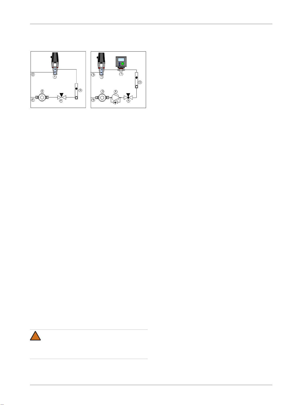
2 Intended use
The Dräger SAM 3100/SAM 3200 is an aspirator system for
continual intake of gas/air mixtures for a gas transmitter
(SAM 3100) or for two gas transmitters (SAM 3200), in order
to carry out measurements of toxic and/or explosive
substances in hard-to-access places.
In the event of insufficient process overpressure, a partial flow
of the process gas is siphoned off from the process using
a gas sampling pump with electric drive, or alternatively using
an ejector.
In order to separate solid particles from the gas flow,
the gas is passed across a filter.
The sample gas is passed to the flow meter with ring
initiator (for flow monitoring) via a 3/2-way spherical valve
(option for simplified feeding of test gas) and then flows into
the sample chamber of the sensor or sensors.
The air is either discharged to atmosphere or fed back
to the intake point by means of the air outlet on
the transmitter.
WARNING
The equipment is only approved for use in potentially
explosive atmospheres when using components
suitable for such areas, complete with test certificate.
Risk of explosion!
WARNING
Indicates a potentially hazardous situation which, if not
avoided, could result in death or serious injury.
CAUTION
Indicates a potentially hazardous situation which, if not
avoided, could result in physical injury, or damage to
the product or environment. It may also be used to
alert against unsafe practices.
NOTICE
Indicates additional information on how to use
the product.
WARNING
During installation without return feed for the sample
gas back to the intake point, the sample gas should be
guided to a vent or outside. Risk of poisoning or
explosion! The return feed must not be pressurised.
!
i
i