Dr. Kern Tan Can 4000 User manual

1
29492854 / 08.06 20013492
INSTALLATION AND USER'S GUIDE
FOR SUNSHOWER
Tan Can 4000
Tan Can 8000

2
Contents
Please note! ........................................................................................................................ 3
Interesting facts about tanning ........................................................................................ 3
General safety precautions ............................................................................................... 3
Tanning times ..................................................................................................................... 4
Tanning program ............................................................................................................... 4
After tanning........................................................................................................................ 4
System installation............................................................................................................... 5
Operation ............................................................................................................................ 9
Operation ia external timer control .................................................................................. 9
Modification to coin box operation .................................................................................. 11
Resetting to timer operation .............................................................................................. 11
Freeze the appointed time.................................................................................................. 11
Timer adjustment ................................................................................................................11
Cleaning the sunshower and the acrylic plates ............................................................ 12
Replacing UV tubes and starters ..................................................................................... 12
System exhaust configuration ......................................................................................... 12
Technical specifications .................................................................................................... 12
Warranty ............................................................................................................................ 13

3
Dear Customer,
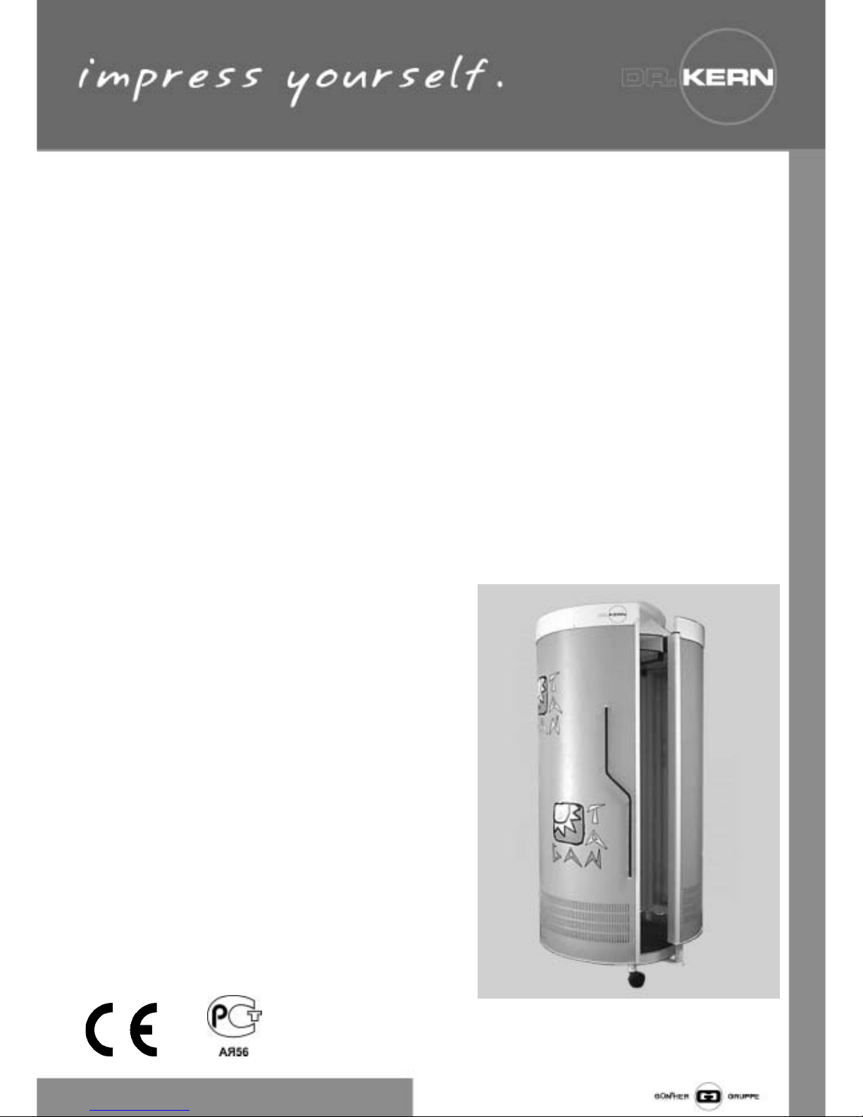
With your purchase of a Dr. KERN ta i g system, you
have opted for a tech ically superior, high-performa ce
u it. Our productio staff has made every effort to e sure
the reliable, trouble-free operatio of your Dr. KERN
system.
There is also a great deal that you ca do to e ha ce
your satisfactio a d exte d the life of your ta i g system.
Please read the User's Guide carefully a d i stall the
equipme t i accorda ce with the i stallatio i structio s
e closed. Proper i stallatio is esse tial to flawless
ta i g system performa ce.
Please note!
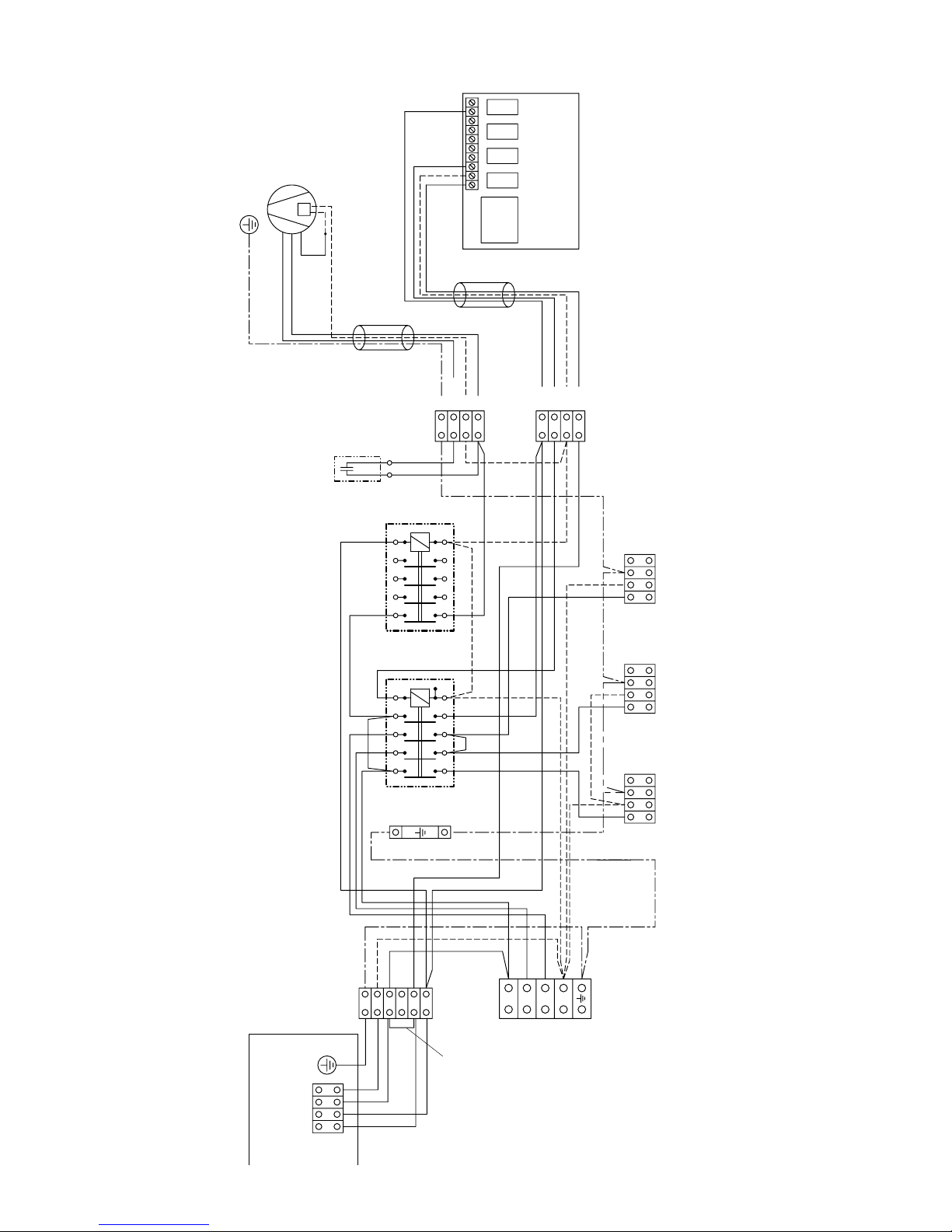
The ta i g system is desig ed for a fixed co ectio
with separator to a 380-400 V 3NAC power outlet (or for
a CEE plug co ector). I the eve t of power cable
replaceme t, o ly type H05W-5 FG 1.52 cable may be
used.
The ta i g system must be i stalled i a dry room a d
kept free of exposure to spray or drop moisture. Maxi-
mum relative humidity a d room temperature should ot
exceed 70% a d 28°C, respectively. Higher room
temperatures ge erate higher temperatures o the be ch
surface a d u der the su hood.
Air i take slots a d hot air exhaust ve ts o the cooli g
fa s must ot be blocked or covered, as the system may
otherwise overheat.
I case of fa failure-which results i u usual heati g of
the ta i g applia ce-tur the equipme t off immediately.
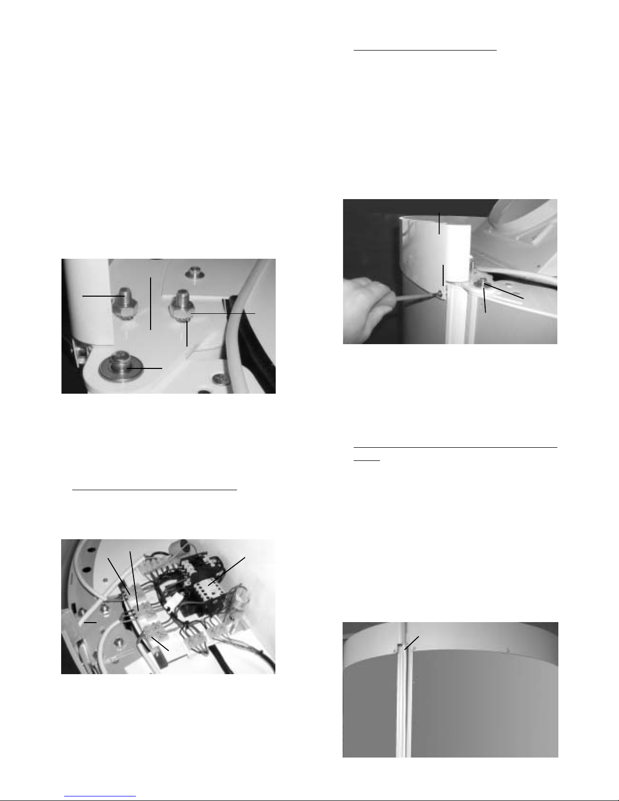
Always disconnect the system from the power source
when performing work on the system (replacement of
tubes/bulbs and starters or cleaning operations).
Repairs to the ta i g system may be carried out o ly by
a locally certified electricia or by pla t customer service
perso el.
Whe i stalli g the ta i g system, please e sure that
the floor has sufficie t load-beari g capacity (mi . 4.5
KN/m2 ). If the capacity is lower, the i staller must fur ish
appropriate docume tatio .
The acrylic plates i the system have prove to be
i compatible with several cosmetics a d clea sers
curre tly o the market. Compatibility with our product
ECOCLEAN has bee tested, a d the use of these products
is safe for the equipme t. We assume o liability for
damage to the acrylic plates caused by chemical products
of other ma ufacturers.
Attention!
This unit has an exhaust air system which only works
properly with an sufficient incoming and outgoing air.
The warranty expires if the requirements will not be
fulfilled.
Interesting facts about tanning
The radiatio of the ta i g u its is of a optimal
compositio . The special lamps emit a particularly high
proportio of mild UV-A ta i g rays. This avoids su bur
while allowi g the ski to ta i the shortest possible
time.
Aside from the cosmetic effects, reaso able exposure to
ta i g rays ca promote overall physical well-bei g
a d may, i additio , have a favorable i flue ce o a
variety of ski disorders. Perso s with k ow health
disorders, however, should always co sult a physicia
prior to ta i g. The ta i g applia ce ca produce its
optimal ta i g effect o ly whe ormal preco ditio s
which are required for ta i g i su light are prese t.
The radiatio of the ta i g applia ce will have o
ta i g effect o perso s whose ski does ot ta i
su light.
General safety precautions
UV applia ces must ot be used by perso s who su bur
i su light without ta i g their ski (Ski type I), perso s
who show a te de cy to su bur , childre u der 16 years
of age, or by perso s who have suffered from ski ca cer
or who have a te de cy to do so.
The recomme datio s specific to the i dividual u it
regardi g the ta i g times a d radiatio i tervals must
be observed.
Do ot use the system if the time co trol u it is defective
or the filter glass is broke .
Ultraviolet exposure (radiatio ) from the su or from UV
applia ces ca lead to damage to the ski or eyes. The-
se biological effects depe d o the type a d qua tity of
exposure (radiatio ), as well as o the se sitivity of the
ski of the i dividual.
The ski may exhibit su bur after excessive ta i g.
Overly freque t repetitio of ultraviolet ta i g sessio s
with su light or UV applia ces may lead to premature
agi g of the ski as well as to a i creased risk of ski
tumors.
Without the use of protective eyewear, eyes ca become
i flamed o the surface, a d i certai cases excessive
exposure to UV light may damage the reti a. Ma y
repeated ta i g sessio s may lead to the formatio of
grey cataracts.
Special care must be take i cases of particular se sitivity
of some i dividuals to ultraviolet radiatio , as well as i
cases where certai medicatio s or cosmetics are bei g

4
Tanning Times
Ski type Descriptio Desig atio Max. su light
exposure time
without
protectio
Reactio to su light
Su bur Ta i g
Ski : extremely light
Freckles: very oticeable
Hair: reddish
Eyes: blue, seldom brow
Nipples: very light
I
Celtic type
(2%)
o ly,
severe,
pai ful
o e,
redde i g,
tur s white after 1-2
days, ski peels
5-10
mi utes
Ski : somewhat darker tha I
Freckles: seldom
Hair: blo de to brow
Eyes: blue, gree , brow
Nipples: light
II
10-20
mi utes
egligible,
ski
peels
always,
severe,
pai ful
light-ski ed
Europea
(12%)
III
Ski : light to light brow
Freckles: o e
Hair: dark blo de, brow
Eyes: grey, brow
Nipples: darker
dark-ski ed
Europea
(78%)
20-30
mi utes
averageseldom,
moderate
Ski : light brow , olive
Freckles: o e
Hair: dark brow
Eyes: dark
Nipples: dark
IV
Mediterra ea
type
(8%)
40
mi utes
quick
a d
deep
egligible
Therefore, the followi g safety precautio s must be
observed:
Always use protective goggles.
Remove cosmetics in time for tanning and do not
use any type of sunscreen agent.
Do not tan when taking medication which increases
the sensitivity of the skin to ultraviolet radiation. If in
doubt, consult a physician.
Always leave a break of one day between tanning
sessions and do not have a sunbath on the same
day.
Follow recommendations concerning tanning times,
intervals and distances.
Visit your physician if the skin displays persistent
swelling, sores or pigmented moles.
After tanning
It is advisable to apply a moisturizi g lotio to the ski
after ta i g.
Tanning program
Usi g data which coordi ates ski types with the radiatio
source i tegrated i your ta i g system,
a ta i g program has bee determi ed for your ta i g
system i accorda ce with the recomme datio s of EN
60-335-2-27. This program accompa ies your ta i g
system as pri ted matter.
The beginning and maximum exposure times must not
be exceeded.

5
System assembly is described step by step i the followi g
sectio s. Please e sure that electrical wiri g a d
co ectio is performed by a certified electricia i
keepi g with VDU a d local EVU regulatio s.
ÀBaseplate
Begi the assembly by removi g the baseplate (D)
from package 4, a d placi g it at the i te ded locatio
of the system.
Note:
The baseplate must be placed flat and level! For
orie tatio purposes, the rear positio i g to gue is
provided with a adhesive label.
E
A
B
C
Fig. 1
D
Fig. 2
ÁRight tanning element
Remove the right eleme t (A) from package 1. You must
ow carry out the i itial assembly of the two sta d
feet.
Stand foot, facing side lower right:
From the accessory pack, take the sta d foot (4), two
M10 uts (5) a d washers (6), a d assemble the foot
as show i Fig. 3.
Fig. 3
4
5/6
Stand foot, facing side lower left:
From the accessory pack, take the sta d foot (7), two
M10 uts (5) a d washers (6), a d assemble the foot
as show i Fig. 4
Fig. 4
7
6
5
E sure that the i stallatio plate of the sta d foot is
correctly positio ed for co ectio to the ext eleme t
(Fig. 4).
ÂLeft tanning element
Remove the left eleme t (B) from package 2, a d
assemble the sta d foot (8) as follows:
From accessory pack 2, take 2 dista ce collars (9), two
M10 uts (10) a d 2 lock-washers (11), a d assemble
as show i Fig. 5.
Note: The beari g (12) for the door eleme t is already
fitted i sta d foot (8).
9
12
10/11
8
Fig. 5
1
14
13
System Installation
The system is delivered i several separately packed
sectio s for tra sport to its fi al i stallatio poi t. The
complete package co tai s the followi g i dividual
eleme ts:
A right ta i g eleme t (package 3)
B. left ta i g eleme t (package 2)
C. door ta i g eleme t (package 1)
D. base
E. exhaust u it

6
Fig. 6
13
ÃInstalling the tanning elements
preassembled in steps 2 and 3
I stallatio of the right eleme t
Lift the eleme t a d place it i the to gues provided
(13 + 1) i the baseplate (Figs. 6 a d 7).
Note!
The element will need to be held in place by one
person.
Fig. 7
1
13
Installation of the left element
Lift the eleme t a d place the lower right side o the
i stallatio plate of the sta d foot (7) (Fig. 8).
Fig. 8
7
6
5
Now lift the sta d foot (8) o the lower left side i to the
positio i g to gue (14) i the baseplate (Fig. 9).
The curre t assembly co ditio is show i Fig. 10.
Fig. 9
Fig. 10
1
13
14
Bolting together the two elements at stand foot (7).
For this step, you will eed two M10 uts (5) a d 2 lock-
washers (6) from the accessory pack (Fig. 8).
Bolting together the two elements at the top
For this step, you will eed the i stallatio plate (15), 4 uts
(5) a d 4 lock-washers (6) from the accessory pack.
M10 bolts (16) are provided i the upper sectio s of both
eleme ts. Place the i stallatio plate with its holes over
the bolts (16), a d fix it firmly i place usi g the uts (Fig.
11.
The two ta i g eleme ts are ow assembled.
Note: Check the correct position in relation to the
baseplate and the aligned position!
Note! Both elements must be held in the upright position
until they are bolted together.
5
15
Fig. 11
6
16
16
14
14

7
ÄInstallation of the exhaust unit
Remove the followi g parts of the exhaust u it (E) from
package 4:
- Ceili g plate (17) with i tegral ce tral fa a d
operati g pa el (18)
- Exhaust duct (19) with two bypass hoses (20)
These two parts must be bolted together. To do this,
remove the pre-assembled bolts (21) from the ceili g
plate (17), place the exhaust duct with its attachme t
holes i positio o the ceili g plate, a d the refit the
bolts (21) (Fig. 12).
Fig. 12
21
20 19
Fig. 13
17
18
Note: The operating panel (18) must not be bolted to the
lower plate yet!
The complete exhaust u it is ow lifted o to the ta i g
eleme ts (Fig. 13).
Now place the attachme t holes i the exhaust u it over
the matchi g holes i the ta i g eleme ts.
Use 6 hex-head bolts (22) with washers (23) from the
accessory pack to bolt the exhaust u it i place (Fig. 14)
23
22
Fig. 14
Now bolt the operati g pa el (18) to the lower ceili g
plate (Fig. 13), usi g the bolts provided i the accessory
pack.
The followi g auxiliary eleme ts are built i to to ceili g
plate of the TAN CAN 8000
- 2 air jets for the head area
- 2 loudspeakers for co ectio to a exter al audio
system
- co trol u it
Fig. 15
Å Installing the door element
Remove the door eleme t (C) from package 3.
Note: The retai i g bolt (25) for the castor, a d the
upper a d lower beari gs (27) a d (32) are already
fitted to the door eleme t (Figs. 16 - 18).
Fig. 16
26
25
Fig. 17
24
27
8
12

8
Now screw the castor (26) o to the retai i g bolt (25) (Fig.
16).
Lift the door eleme t with the pre-assembled beari g
bolt (27) o to the i stallatio plate (12), a d slide the
beari g i to place.
To assemble the upper beari g (Fig. 18), you will eed the
i stallatio plate (28), which is first loosely assembled
usi g the two threaded bolts (29), the uts (30) a d lock-
washers (31).
Swi g the door eleme t over the i stallatio plate (28) so
that the upper beari g poi t of the door eleme t (32) is
positio ed opposite the ope i g i the i stallatio plate
(28).
Now let the i stallatio plate (28) drop dow over the
upper beari g, a d tighte the two uts (30) firmly (Fig.
18).
29
28
30
31
Fig. 18
32
ÆElectrical connection of the elements
All 3 eleme ts have their electrical co ectio s at the
top, a d are co ected to the co trol u it (33) by mea s
of the 3 plugs (34 - 36) (Fig. 19).
Fig. 19
3334 35
36
ÇInstalling the upper trim panels
Fi ally, fit the three trim pa els (37) arou d the upper
edge of the system (Fig. 20), usi g for each pa el two
self-tappi g screws (38) o the outside, a d two M4
screws i the ce tral area.
E sure that a dista ce sleeve is placed betwee the
trim pa el a d rear wall of the u it at each attachme t
poi t.
32
28
37
38
Fig. 20
ÈInstallation of main connection cable / cover
panel
The mai co ectio cable (39) is pre-assembled to
the co trol u it (33), a d lies rolled up o the exhaust
u it.
Take the cable (39) a d lead it dow alo g the side of
the system (Fig. 21).
The fit the cable te sio -relief device (40) (from the
accessory pack) to the cable (Fig. 22).
Now remove the cover pa el (41) from package 3, a d
fit it as show i Fig. 23.
Note: The existi g screws i the rear walls are used
for the attachme t of the cover pa el (41). These screws
must be removed before fitti g the cover pa el.
Fig. 21
33 = Co trol u it
34 = Co ectio cable, right eleme t
35 = Co ectio cable, left eleme t
36 = Co ectio cable, door eleme t
39 = Mai co ectio cable
39
39

9
Fig. 25
ON/OFF
8.8.
ÀÁ ÄÃÂ
Fig. 24
Fig. 23
Co ect the mai power cable to the mai s power source
usi g a fixed co ectio or a plug co ectio (CECON
plug).
The system is ow ready for operatio .
Fig. 22
41
40
39
The ta i g u it will be switched o by usi g the O /Off-
switch À (fig. ) at the digital-timer.
With the keys à a d Ä (fig. 25) you ca select your ta i g
time (max. 30 mi utes).
Ä= up, Ã=dow
After loose of time the digital timer of the ta i g u it switches
off automatically.
After ta i g sessio the u it is switchi g over to after
cooli g mode for 3 mi utes.
Operation
Attention: he switches Á and  are inoperable
in this tanning appliance.
Operation via external timer control
Further o you ca use your ta i g u it via exter al
timer co trol (e.g. coi box). The co ectio is to be made
accordi g to the followi g wiri g diagram.
Please pay atte tio , that a co trol li e for the fa delay
has to be available i either case.
The co ectio li e betwee the applicatio a d the
exter al timer co trol is i ducted i to the applia ce
besides the mai co ectio li e a d applied to the
co ectio termi al (fig.26).

10
Fig. 26
control board
Segment 1 Segment 2 Segment 3
1C
main fan
main connection
coin box
coin box
(use only coin box
with fan delay)
C1= capacitor 5µF
SD = inductor for earth conductor
1K=
contactor for fans
2K=
contactor for lamps
rechts/rightTür/door links/left
remove jumper
fan
L
time
N
4
NPE
123
L1 L2 N PE
4213
PEL3 N
1234
L1
N
time
1324
LN
L
1234
PE
N
startup
SD
PE
N
L3
L2
L1
LN
time
time
fan
NC
L
L
N
N
PE
TH
gn-ye
br
bl
grey
bl
24 146A2264
31135A1531
14 A2
13 A1
K2K1
2Kl
1Kl
1Bu 2Bu Bu3
3
Kl
Kl4

11
Fig. 27
Fig. 28
Mo ification to coin box operation
For this procedure 2 perso s are eeded.
lIf the coi box is ot co ected yet, separate the
applia ce completely from power supply.
lDuri g o e perso keeps pushi g simulta eously the
up a d dow butto at the timer, the other perso is
co ecti g the applia ce to power supply agai .
lIf the coi box is already co ected, the applia ce
must ot be separated from the power supply.
I this case follow the i structio s below:
- o e perso keeps pushi g simulta eously the up
a d dow butto at the timer.
- the other perso starts ru i g the coi box by
throwi g i a coi
lKeep pushi g the up a d dow butto as lo g as 0
appears o the timer display (fig. 27).
The applia ce is ow coi box operated.
After release by the coi box the timer is goi g from 0
mi utes upwards.
The applia ce ca be started a d stopped.
The up a d dow butto s are locked. The other butto s
keep their fu ctio .
Resetting to timer operation
The resetti g is o ly possible, if the coi box is separated
a d the wire jumper L1-Time is mou ted (see
co ectio diagram o fig. 26).
For this procedure 2 perso s are eeded.
lSeparate the applia ce completely from power supply.
lDuri g o e perso keeps pushi g simulta eously the
face ta er a d body fa butto at the timer, the other
perso is co ecti g the applia ce to power supply
agai .
lKeep pushi g the face ta er a d body fa butto
as lo g as 88 appears o the timer display (fig. 28).
lAfterwards the display expires.
The applia ce is ow timer operated.
Whe the time is over, the applia ce is completely
switched off a d the timer display expires.
Attention: The fan delay has to be executed by the coin
box!
Fig. 29
Freeze the appointe time
lTu e the favoured ta i g time at the timer.
lPush the butto "fa " a d " upward" at the same time
(fig. 29).
Now the su bed is worki g as lo g as the appoi ted
time is expired.
I betwee it is ot possible to shift the time, the botto s
are blocked. But the su bed ca be switched off a o .
By switchi g o agai the bala ce time elapses. After
ru of time the su bed cuts off a d a ew time ca be set.
Timer a justment
jumper 2 jumper 1
jumper 1 (time period):
ope ed = maximum period 30 mi
closed = maximum period 60 mi
jumper 2 (fa delay)
ope ed = without fa delay
closed = with fa delay

12
Fig. 30
49
50
Fig. 31
52
51
Fig. 32
54 53 55
Cleaning the sunshower an the
acrylic plates
Use a moist cloth to clea the su shower . The acrylic plates
should also be clea ed at regular i tervals. Use o ly sol-
ve t-free, o -caustic a d o -aromatic clea i g age ts.
To remove the acrylic plates, pull each plate forward from
its positio , grippi g the profile bars o the side (49) from
behi d as show i Fig. 30. Be d the plate (50) slightly
toward the i side. The press the plate dow a d out of
the mou ti g frame grooves o the sides. The plate ca
ow be clea ed o both sides.
Replacing UV tubes an starters
To replace tubes a d starters, first remove the acrylic
plates as described above.
The UV tubes i your ta i g system must be replaced
after a certai umber of operati g hours.
The effective service life of the UV low-pressure tubes is
about 500 hours. Please e sure that o ly origi al
replaceme t parts are used whe replaci g tubes a d
starters. Replaceme t parts ca be ordered from
customer service or your local dealer. Please i dicate
the system umber (see ID plate). This applies to orders
for all replaceme t parts.
UVA low-pressure tubes (53) are removed/i serted by
tur i g them 90! i their sockets (54) both above a d
below a d pulli g them forward. Whe i serti g ew
tubes, please e sure that the co tact pi s o the tubes
are fitted properly i to the sockets.
After clea i g, replace each plate i the followi g ma er:
Set the lower edge of the plate o the pi (51), grip the
side profile bars a d press the outer edge of the plate
(52) agai st o e edge of the mou ti g frame.
The be d the plate slightly toward the i side a d press
u til the opposite edge locks i to place o the other edge
of the mou ti g frame. Fig. 31.
Technical Specifications
Tan Can 4000
Lamp tubes: 33 x 100 W UVA reflectorlamps
30 x 25 W spaghettilamps
Nomi al power output: 4700 W
Circuit breakers: 3 x 16 A
Nomi al voltage: 3N AC 400 V
Power cable: 5 x 1,5 mm²
Dime sio s:
Outside dime sio s: Æ 1.1 m, height 2.45 m
I side dime sio s: Æ 0.88 m, height 2 m
Exhaust hose: Æ 300 mm
System exhaust configuration
Exhaust air should be removed from your su shower via
a hose. Please take the followi g poi ts i to accou t with
regard to the co figuratio of the exhaust system.
Outside temperature has a co siderable impact o
system operatio . Ideally, outside temperature should
be 28! with a relative humidity of 70%. Use o ly 300-mm
hose for the exhaust li e. Ideally, exhaust hose should
lead i a straight li e up a d away from the cell. Be ds i
the hose ge erate air-flow resista ce. Avoid 180! be ds
i all cases. Give a straight exhaust li e co figuratio ,
exhaust hoses ca be as lo g as 2 m without the eed
for a additio al blower u it. If the exhaust li e is lo ger
tha 2 m or has be ds, the additio of a auxiliary blower
u it is recomme ded i order to e sure effective exhaust
air removal. Hose output diameter should ot be reduced
at a y poi t i the exhaust li e, as this may result i air
blockage.
Starters (55) are located at the upper e ds of the tubes
a d are removed/i serted by tur i g them 90° a d out
of their sockets. Fig. 32.
Lamp tubes: 48 x 160 W UVA reflector tubes
Nomi al power output: 8500 W
Circuit breakers: 3 x 16 A
Nomi al voltage: 3N AC 400 V
Power cable: 5 x 1.5 mm²
Dime sio s:
Outside dime sio s: Æ 1,1 m, height 2,45 m
I side dime sio s: Æ 0,88 m, height 2 m
Exhaust hose: Æ 300 mm
Tan Can 8000

13
Please note!
Waste Disposal Law of 27 August 1986
Ta i g tubes require separate disposal measures
as hazardous waste materials.
Local commu ities provide for disposal of tubes
from private homes a d commercial e terprises at
desig ated hazardous-waste collectio poi ts.
Tubes must be delivered i tact for disposal.
Service address:
DR. KERN GmbH
Adolf-Weiß-Straße 43
35759 Driedorf, Germa y
Tel. +49 (0)2775 82-240
Fax +49 (0)2775 82-455
servicece ter@dr-ker .de
www.dr-ker .de
Please keep this address i a safe place together with the
i stallatio guide.
To help us a swer your questio s quickly a d compete tly,
please provide data pri ted o the ID plate, to i clude
system type, article o. a d serial o., i all i quiries.
$
Guarantee
The guarantee is taken over according to the legal regulations
at present.
Manufacturers warranty
The period of warranty starts from the date of purchase and
lasts upto 12 months.
- Always include the completed warrenty certificate when
returning equipment.
- The warranty expires for appliances which have been
modified without manufacturer s explicit agreement.
- Damages caused by incorrect operation or handling through
non-authorized persons are not covered under the terms of
warranty.
- In the event of a claim, please indicate the serial number as
well as the article code number and type name with ex-
pressive description of the fault.
- This warranty covers damaged parts but no defects due to
wear and tear.
In case of complaint please return the equipment in its original
packaging or other suitable packaging (caution: danger of
transport damage) to our service department.
Always include the completed warranty certificate when
returning equipment. Possible shipping costs arising from the
transport to and from point of repair cannot be borne by us.
Always include the completed warranty certificate when
returning equipment.
Outside of Germany please contact your specialist dealer in
case of warranty claims. Direct warranty processing with our
service department is in this case not possible.
Equipment start-up date:
Stamp and signature of the authorized electrician:
This manual suits for next models
1
Table of contents
Other Dr. Kern Personal Care Product manuals
Popular Personal Care Product manuals by other brands

BIOCORP
BIOCORP Mallya Instructions for use

Omron
Omron WheezeScan HWZ-1000T-E instruction manual

SOLTRON
SOLTRON XL-80 Fresh peppermintDynamic power operating instructions

Juzo
Juzo Compression segments Instructions for use

Remington
Remington Reveal Pro Collection MAN3000 user manual

BaByliss
BaByliss 3045BU manual