Copyright © 2001-2018, Dr Robot Inc. All Rights Reserved.
www.DrRobot.com
V.07.08.18.Q
- 5 -
I. Specifications
Jaguar 4x4 Wheel with Arm Mobile Platform is designed for indoor and outdoor operation requiring higher
ground clearance and faster maneuverability. It comes with a rugged 3+1DOF robotic arm (Jaguar Arm), Jaguar
Arm is light on weight, low on power consumption and compact on size. It has 3 DOF + 1 DOF gripper, with
maximum reach of over 710mm (28 in), max payload capacity of 4Kg at max reach, while weights under 10Kg.
Wrist mounted color video camera provides high resolution (640x480) close-up view. Jaguar Arm is ideal or
objectinspectionand handling. Itcould alsoworkas anarticulated sensorplatform. Integrated softwarefeatures
independent joint space control as well as gripper Cartesian space control. While it only has 3 rotation joints
(excluding gripper), when working together with the Jaguar 4x4 Wheel mobile robot, Jaguar Arm could achieve
full6DOF,andreachvirtuallyanypositionandatanyorientationwithinitsallowedworkingspace.
Jaguar 4x4 Wheel with ArmMobile Platform is driven by fourpowerful (105W) motors, one for each wheel. This
platform is rugged, light weight (< 33Kg), fast (max 7km/hr), with high ground clearance (88mm), compact,
weather and water resistant. It is designed for tough terrains and capable of running over vertical step up to
155mmandclimbinguplowrisestairs(upto110mmstep).Jaguar4x4wheelwithArmPlatformisfullywirelessly
802.11Nconnected.Itintegratesoutdoor GPSand9DOFIMU (Gyro/Accelerometer/Compass)forautonomous
navigation.The integratedhigh resolutionvideo/audioand optionallaser scannerprovideremote operatordetail
information of the surrounding. Besides the ready to use control and navigation software, a full development kit
includingSDK,dataprotocolandsamplecodes,isalsoavailable.
Key Features
Ruggedandreliablemobileplatformforindoorandoutdoorapplicationswith fastermaneuverability (max 7Km/hr)
Indoorandoutdooroperationrequiringhighergroundclearanceandontough terrains
Weatherandwaterresistantenclosure
Climbingup>45°slopeorstairs(max110mmor4.5")
Lightweight(<33Kg)andcompactdesignwithlargepayloadcapacity
Autonomousnavigation withoutdoorGPSand9DOFIMU(Gyro/Accelerometer/Compass)
Managingmax155mm(6")verticalstep(obstacle)
Integratedhighresolutionvideocamerawithaudio
All802.11Nwirelesslyconnected
Ruggedroboticarm(3DOF+1DOFgripper)
Compact,lightweightanddurablewithaluminummainconstructionManipulatorArm
710mm(28in)reachwithmax 4Kg payload (ManipulatorArm)
Lowenergyconsumption
Widegripperopening(150mm/6in)
Integrated joint-spaceandgripperCartesian spacearm control
Wristmountedcameraprovidinghighresolution(720x480)close-upview
Additional on arm option includes Infrared LED, white LED for night and day time illumination, dust blower, laser scanner
and varioussensing devices
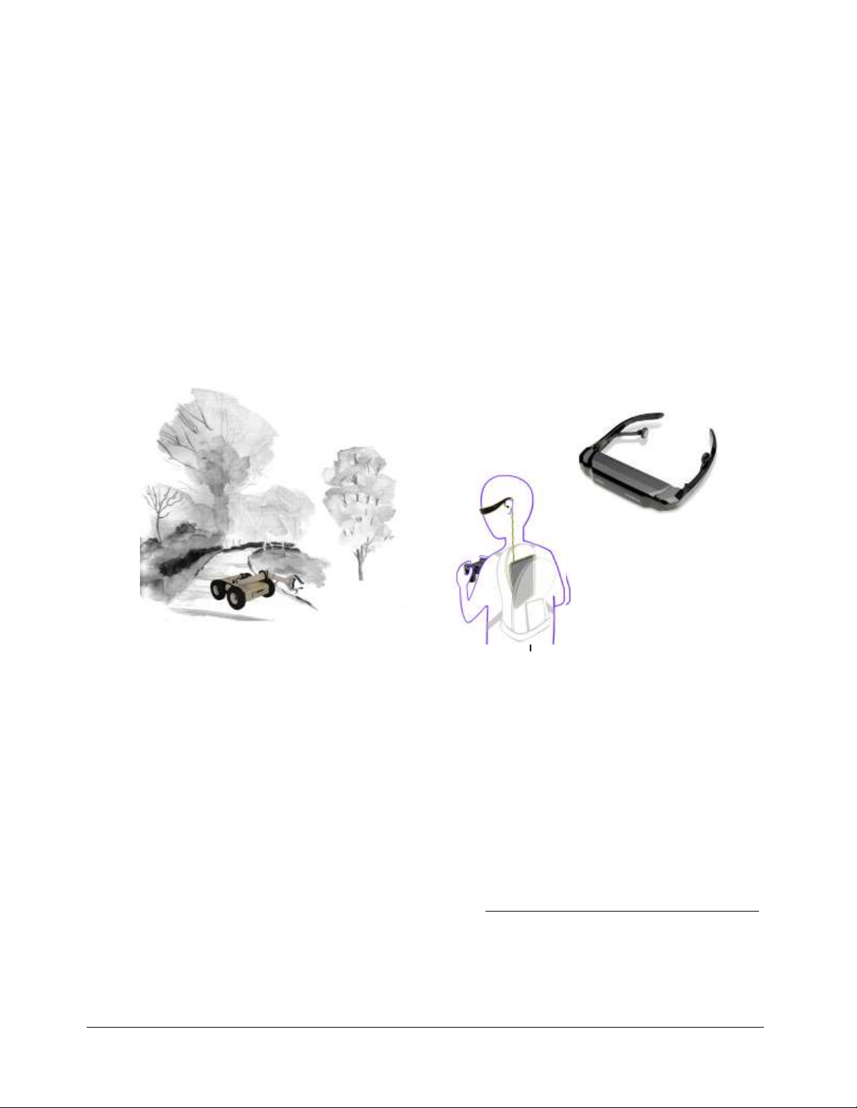
Head mounted display (optional) and Gamepad controller providing outdoor operation with large and clear view even
underdirectsunlight
Integrated laserscanner (Optional)
Readytousecontrol andnavigationsoftware
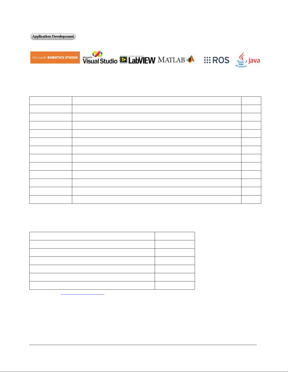
Full development kit including SDK, data protocol and sample codes, supporting Microsoft® Robotics Studio, Microsoft®
VisualStudio,ROS,NILabVIEW®,MATLAB®,Java®