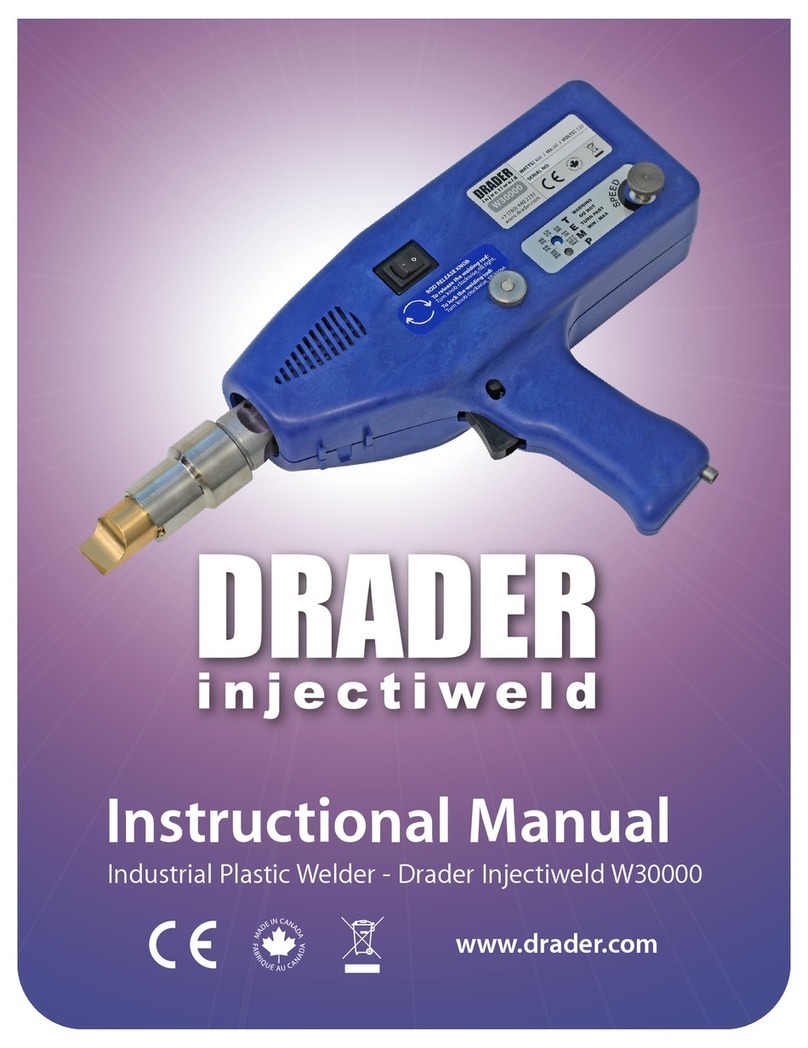
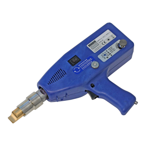
Drader W30000 User manual

W30000 REPAIR PROCEDURE UPDATES
TRIGGER SWITCH REPLACEMENT
Revision 1.0 / 2022-08-23
5750 – 50 Street NW
Edmonton, AB T6B 2Z8
CANADA
1327 Clark Boulevard
Brampton, ON L6T 5R5
CANADA
www.drader.com
NOTICE
Drader Manufacturing Industries Ltd. (Drader) provides no warranty, express or implied, statutory or otherwise as
to the accuracy, and viability of the information, solutions, and opinions provided in this document to anybody.
Contents subject to change without notice.
This is a CONFIDENTIAL AND PROPRIETARY DOCUMENT and should not be distributed outside of the Drader
Injectiweld authorized distributor and/or service centre network and shall be considered confidential information
protected under non-disclosure agreement. DO NOT PROVIDE ANY PART OF THIS DOCUMENT TO END CUSTOMERS
OR ANYONE ELSE!
All trademarked names are the rights of their respective companies.

Table Of Contents
©2022 Drader Manufacturing Industries Ltd. Page 2 of 25
Injectiweld W30000 Repair Instructions R1.0 / Confidential Information
Table of Contents
1. INTRODUCTION......................................................................................................................................... 3
Revision Information................................................................................................................................. 4
SCOPE, PREFACE, AND ASSUMPTIONS ..................................................................................................... 4
SELECTING THE TRIGGER SWITCH............................................................................................................. 5
2. TRIGGER SWITCH REPLACEMENT FOR LEGACY WELDERS ........................................................................ 6
Step 1 – Remove The Old Switch .............................................................................................................. 7
Step 2 – Trim and Prepare Existing Wires................................................................................................. 8
Step 3 – Attach Switch to The Wiring .....................................................................................................10
Step 4 – Screw Switch Into Place ............................................................................................................ 11
Step 5 – Cable Management................................................................................................................... 12
3. TRIGGER SWITCH REPLACEMENT FOR WELDERS WITH PCB REVISION 6 OR LATER .............................. 14
Step 1 – Remove The Old Switch ............................................................................................................15
Step 2 – Trigger Switch Connection ........................................................................................................ 16
Step 3 – Trigger Switch Attachment ....................................................................................................... 18
Step 4 – Cable and Air Hose Routing ...................................................................................................... 19
Step 5 – Cable and Hose Attachment ..................................................................................................... 20
Step 6 – Final Cleanup of Internals .........................................................................................................24

1. Introduction
©2022 Drader Manufacturing Industries Ltd. Page 3 of 25
Injectiweld W30000 Repair Instructions R1.0 / Confidential Information
1. INTRODUCTION

1. Introduction
©2022 Drader Manufacturing Industries Ltd. Page 4 of 25
Injectiweld W30000 Repair Instructions R1.0 / Confidential Information
Revision Information
Revision
Author
Date
Description
R0.1
Mai Kaaver /
Mark Fedorak
2022-08-13
First draft of switch instructions.
R0.2
Mai Kaaver /
Mark Fedorak
2022-08-19
Added the V6 replacement, also general
cleanup.
R0.3
Mai Kaaver /
Mark Fedorak
2022-08-22
Additional cleanup.
R1.0
Mai Kaaver
2022-08-23
Version 1 released.
SCOPE, PREFACE, AND ASSUMPTIONS
Please note that these instructions are intended to guide distributors and service centres with
completing repairs using the best practices as known to Drader Manufacturing at the time. These best
practices are subject to change at any time and this document will be updated accordingly from time to
time.
If during a repair any uncertainty as to the instructions provided in this document occur then please
ensure you contact Drader customer service at csimpson@drader.com, or by telephone at +1 (780) 440-
2231, if you are in North America using the toll free number 1 (800) 661-4122 and we will provide you
with technical support to ensure your repair is completed properly.
A reminder as well that these instructions are confidential and are for internal use by authorized
distributors and service centres. Please do not forward these instructions in whole or in part to any
customers, potential competitors of Drader Manufacturing or any other party who is not part of an
Injectiweld authorized distributor and/or service centre.
SAFETY ALERT:
NOTE: HIGH POTENTIAL DIELECTRIC TESTING AND GROUND BOND TESTING CAN INVOLVE
DANGEROUS VOLTAGES AND CURRENTS AND IT IS IMPERATIVE THAT YOU ARE PROPERLY
TRAINED AND TAKE ALL PRECAUTIONS DURING BOTH THE SETUP, TESTING, AND TEARDOWN OF
THE DEVICE UNDER TEST.

1. Introduction
©2022 Drader Manufacturing Industries Ltd. Page 5 of 25
Injectiweld W30000 Repair Instructions R1.0 / Confidential Information
SELECTING THE TRIGGER SWITCH
Item ID: IPAR-A-SWTRIG
Use the Trigger Switch with item ID IPAR-A-SWTRIG when replacing a Trigger Switch on a legacy welder
that has the trigger switch wired through the on/off switch. Follow the instructions in SECTION 2 of this
document.
If you are replacing the PCB on a legacy welder that has PCB V6 or later but still has the trigger switch
wired through the on/off switch, then you must still use these instructions and use a trigger switch
configured for Legacy configurations as the configuration is different than the directly wired trigger
switches.
If the welder PCB is before V6 and does not have the on-board connector for the trigger switch, please
ensure that you use one of the Legacy Welder replacement kits shown in SECTION 2 of this document.
Item ID: IASS-A-MCSWTRIG
Use the Trigger Switch with item ID IASS-A-MCSWTRIG when replacing a Trigger Switch on a welder that
has the trigger switch wired directly to the PCB. Follow the instructions in SECTION 3 of this document.

2. Trigger Switch Replacement for Legacy Welders
©2022 Drader Manufacturing Industries Ltd. Page 6 of 25
Injectiweld W30000 Repair Instructions R1.0 / Confidential Information
2. TRIGGER SWITCH REPLACEMENT
FOR LEGACY WELDERS
(DRADER PART NUMBER: IPAR-A-SWTRIG)

2. Trigger Switch Replacement for Legacy Welders
©2022 Drader Manufacturing Industries Ltd. Page 7 of 25
Injectiweld W30000 Repair Instructions R1.0 / Confidential Information
Step 1 – Remove The Old Switch
NOTE: If you are replacing a switch that is already wired directly to the PCB then these
instructions do not apply, you should follow the instructions in SECTION 3 of this document.
If you are replacing the PCB on a legacy welder that has PCB V6 or later but still has the trigger
switch wired through the on/off switch then you must still use these instructions and use a trigger
switch configured for Legacy configurations as the configuration is different than the directly
wired trigger switches.
SAFETY NOTICE: Ensure the device is cold, unplugged, and has no air attached.
Remove the screws holding the existing switch from the enclosure and remove the wire from the screws
as per the pictures below. You will likely need to remove the power cord strap and the cable ties in order
to do so.
You may want to inspect all of the wiring to confirm that there is no damage to the trigger wires further
inside the welder.

2. Trigger Switch Replacement for Legacy Welders
©2022 Drader Manufacturing Industries Ltd. Page 8 of 25
Injectiweld W30000 Repair Instructions R1.0 / Confidential Information
Step 2 – Trim and Prepare Existing Wires
Cut and trim the existing trigger wires to a length of approximately 3” from where the trigger wires pass
under the air hose. This will likely be to just trim off the exposed section of wire off of the top wire, and
a bit more off the other wire.
Then strip off 11mm of insulation from each of the old trigger wires so they look like the picture below.
The lever wire nuts on the end of the wires have a strip guide on the side that you can use to measure if
you prefer.

2. Trigger Switch Replacement for Legacy Welders
©2022 Drader Manufacturing Industries Ltd. Page 9 of 25
Injectiweld W30000 Repair Instructions R1.0 / Confidential Information

2. Trigger Switch Replacement for Legacy Welders
©2022 Drader Manufacturing Industries Ltd. Page 10 of 25
Injectiweld W30000 Repair Instructions R1.0 / Confidential Information
Step 3 – Attach Switch to The Wiring
Take the new switch and open the orange levers on the end of the wires. This will open the wire nut,
and then place one wire into each wire nut. It is not important which wire goes to which.

2. Trigger Switch Replacement for Legacy Welders
©2022 Drader Manufacturing Industries Ltd. Page 11 of 25
Injectiweld W30000 Repair Instructions R1.0 / Confidential Information
Step 4 – Screw Switch Into Place
Using the screw that was used previously to hold the trigger switch, place the trigger switch and screw
the switch into place.

2. Trigger Switch Replacement for Legacy Welders
©2022 Drader Manufacturing Industries Ltd. Page 12 of 25
Injectiweld W30000 Repair Instructions R1.0 / Confidential Information
Step 5 – Cable Management
Ensure the power cables and air hose are routed properly including the power cables being pushed
underneath the rod feed tube and the air hose. Then install the Cord Strap (IPAR-A-CRDSTR).
Move the lever wire nuts to their approximate resting location which is approximately 5-10mm from the
Cord Strap. The trigger switch wires should be pushed into the space between the switch and the rod
feed tube as shown below.

2. Trigger Switch Replacement for Legacy Welders
©2022 Drader Manufacturing Industries Ltd. Page 13 of 25
Injectiweld W30000 Repair Instructions R1.0 / Confidential Information
Now apply a cable tie where the cables come out of main support body area of the welder.
The wire routing should now look like the following image.
The installation is now complete and the enclosure reassembly and testing can continue as required. If
the welder under repair had baffles please ensure they are back in place prior to enclosure reassembly.

3. Trigger Switch Replacement for Welders With PCB Revision 6
©2022 Drader Manufacturing Industries Ltd. Page 14 of 25
Injectiweld W30000 Repair Instructions R1.0 / Confidential Information
3. TRIGGER SWITCH REPLACEMENT
FOR WELDERS WITH
PCB REVISION 6 OR LATER
(DRADER PART NUMBER: IASS-A-MCSWTRIG)

3. Trigger Switch Replacement for Welders With PCB Revision 6
©2022 Drader Manufacturing Industries Ltd. Page 15 of 25
Injectiweld W30000 Repair Instructions R1.0 / Confidential Information
Step 1 – Remove The Old Switch
NOTE: If the welder PCB is before V6 and does not have the on-board connector for the trigger
switch please ensure that you use one of the Legacy Welder replacement kits shown in
SECTION 2 of this document.
SAFETY NOTICE: Ensure the device is cold, unplugged, and has no air attached.
Remove the screws holding the existing switch from the enclosure and remove the wire from the main
welder PCB. You will likely need to remove the Cord Strap (IPAR-A-CRDSTR) and some of the cable ties in
order to do so.
You may want to inspect all of the wiring to confirm that there is no damage to the trigger wires further
inside the welder.

3. Trigger Switch Replacement for Welders With PCB Revision 6
©2022 Drader Manufacturing Industries Ltd. Page 16 of 25
Injectiweld W30000 Repair Instructions R1.0 / Confidential Information
Step 2 – Trigger Switch Connection
Take a new trigger switch assembly (IASS-A-MCSWTRIG) as shown below.
Now connect the switch to the PCB as shown below. This is the reverse of what was done to disconnect
and remove the existing switch.

3. Trigger Switch Replacement for Welders With PCB Revision 6
©2022 Drader Manufacturing Industries Ltd. Page 17 of 25
Injectiweld W30000 Repair Instructions R1.0 / Confidential Information

3. Trigger Switch Replacement for Welders With PCB Revision 6
©2022 Drader Manufacturing Industries Ltd. Page 18 of 25
Injectiweld W30000 Repair Instructions R1.0 / Confidential Information
Step 3 – Trigger Switch Attachment
Take a #6-32 x 3/8” long Phillips Pan Head Machine Screw (ISHO-A-EV103)with a #6 Flat Washer (ISHO-
A-EV94) and screw the Trigger Switch into the bottom hole of trigger switch fastening holes until it feels
tight. Be careful not to overtighten it as it will strip the plastic.

3. Trigger Switch Replacement for Welders With PCB Revision 6
©2022 Drader Manufacturing Industries Ltd. Page 19 of 25
Injectiweld W30000 Repair Instructions R1.0 / Confidential Information
Step 4 – Cable and Air Hose Routing
Place the Power Cord wires and the Trigger Switch wires underneath of the feed tube as shown in the
picture below. Make sure the power cord wires are on the cylinder side of the rod feed tube and below
the air hose.
Take the Air Hose and fold it along the inside of the Housing handle between the Rod Feed Tube and the
Trigger Switch or along the top of the Rod Feed Tube such that is exits the Housing beside the Rod Feed
Tube. There is an opening in both Housing halves for the Power Cord, Air Hose and Rod Feed Tube to
exit the Housing.

3. Trigger Switch Replacement for Welders With PCB Revision 6
©2022 Drader Manufacturing Industries Ltd. Page 20 of 25
Injectiweld W30000 Repair Instructions R1.0 / Confidential Information
Step 5 – Cable and Hose Attachment
Using the cord strap (IPAR-A-CRDSTR) and a #6-32 x 3/8” long Phillips Pan Head Machine Screw (ISHO-A-
EV78)place the Cord Strap as shown below ensuring that the Rod Feed Tube, Air Hose, and Power Cord
are underneath of the strap. The slot in the Cord Strap should be right above the larger screw boss in the
Housing back half, and the hole in the Cord Strap should align with the smaller screw boss in the Housing
back half. Then tighten the screw down with a Phillips #2 Screwdriver until feels tight. Be careful not to
overtighten it. The screwdriver handle shown in the picture below is there to provide guidance for the
cable and provide just a little bit of slack.
Other manuals for W30000
2
Table of contents
Other Drader Welding System manuals
Popular Welding System manuals by other brands

Miller
Miller D-74 Boom w/Drives owner's manual

ALDI
ALDI WORKZONE TITANIUM+ PLASMA 35 instruction manual

Kemppi
Kemppi Kemppi A7 MIG Welder 350 operating manual

Miller Weldmaster
Miller Weldmaster Triad Extreme manual

Würth
Würth WIG 180 AC/DC Translation of the original operating instructions

Magmaweld
Magmaweld Monostick 180i user manual