8Technisches Handbuch | FPS 7000FPS 7000 RP
de | Wartungsarbeiten
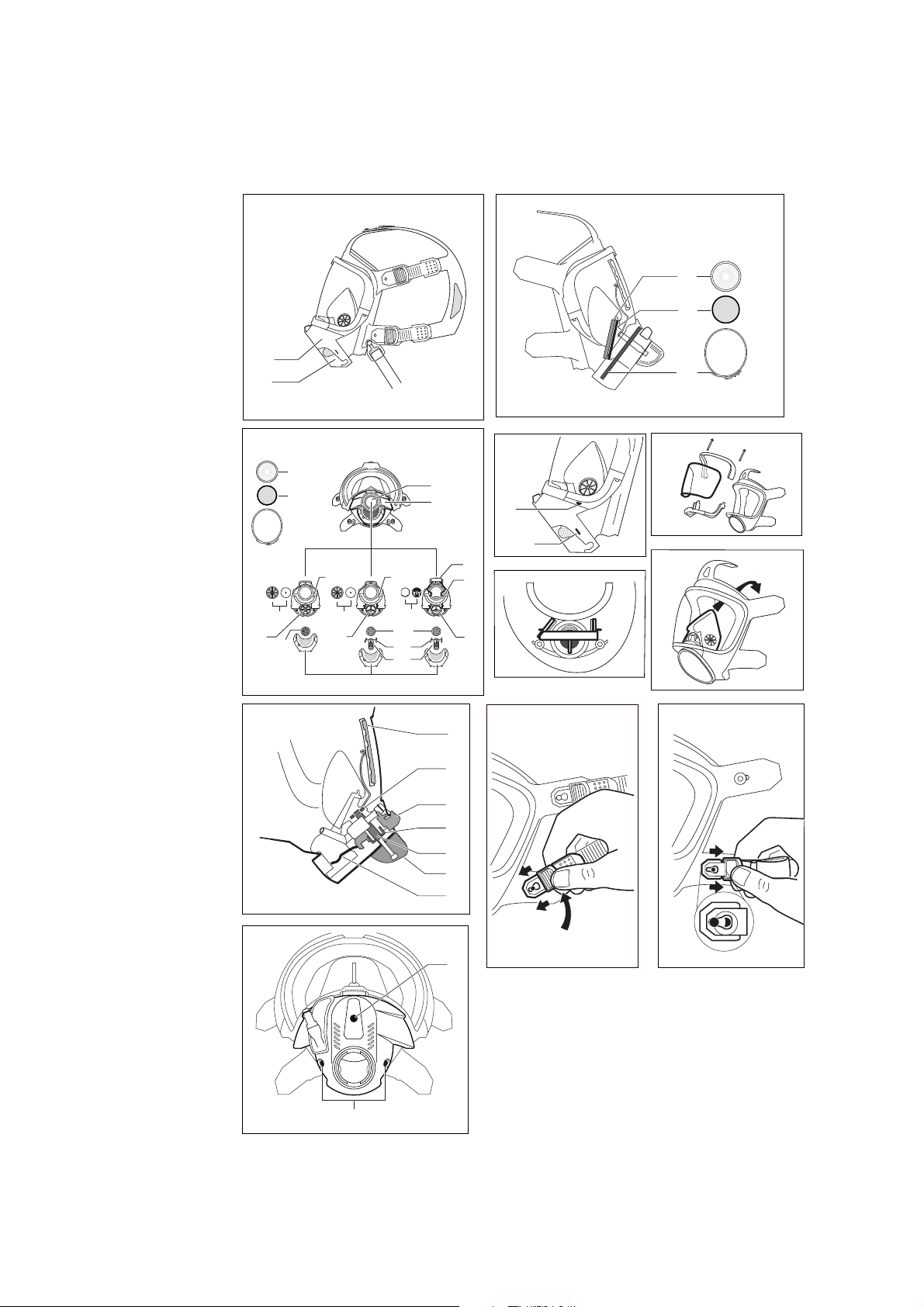
3.7 Einatemventil austauschen
3.7.1 Maske mit Anschluss P
1. Die Taste am Anschlussstück drücken.
2. Den Einatemventilsitz mit Ventil aus dem Anschlussstück
ziehen. Dabei das Anschlussstück nicht beschädigen.
3. Die Ventilscheibe und der Ventilsitz müssen sauber und
unbeschädigt sein, sonst reinigen oder austauschen.
4. Den Einatemventilsitz mit Ventil in den Atemanschluss
einsetzen.
3.7.2 Maske mit Anschluss PE oder RA
1. Den Einatemventilsitz mit Ventil aus dem Anschlussstück
ziehen. Dabei das Anschlussstück nicht beschädigen.
2. Die Ventilscheibe und der Ventil sitz müssen sauber und
unbeschädigt sein, sonst reinigen oder austauschen.
3. Den Einatemventilsitz mit Ventil in den Atemanschluss
einsetzen.
3.7.3 Maske mit Anschluss ESA
1. Um den Ventilsitz herauszunehmen, mit einem
Dichtringausheber unter dem Rand des Ventilsitzes
ansetzen. Dabei das Anschlussstück nicht beschädigen.
Nicht mit einer Zange an den Stegen des Ventilsitzes
ziehen.
2. Die Ventilscheibe und der Ventilsitz müssen sauber und
unbeschädigt sein, sonst reinigen oder austauschen.
3. Den Einatemventilsitz mit Ventil in den Atemanschluss
einsetzen.
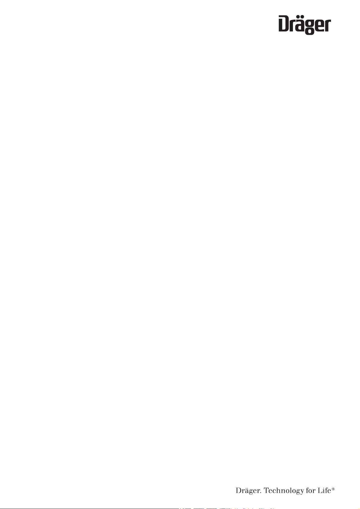
3.8 Anschlussstück austauschen
3.8.1 Anschlussstück austauschen
(FPS 7000 RA/PE/ESA/P)
1. Die Innenmaske ausknöpfen.
2. Die Kappe auf beiden Seiten aus dem Spannrahmen
aushaken (siehe Ausklappseite Abbildung B1-1).
3. Mit dem Daumen unten auf die Kappe drücken und die
Kappe von den Befestigungsnasen lösen (siehe
Ausklappseite Abbildung B1-2).
4. Die Kappe nach oben von dem Atemanschluss abziehen.
5. Die Schelle mit einem Schraubendreher aufhebeln und
entfernen.
6. Das alte Anschlussstück herausziehen.
7. Ein neues Anschlussstück an der Mittenmarkierung
ausrichten und formschlüssig einsetzen.
8. Eine neue Schelle ausrichten und montieren: Den Haken
so einhängen, dass die Schelle möglichst stramm sitzt.
Die Nase der Schelle mit der Zange R 53 239
zusammendrücken, bis der Maskenanschluss fest im
Maskenkörper sitzt.
HINWEIS
Je nach Atemanschluss ist die Aussparung für das
Anschlussstück unterschiedlich. Darauf achten, dass
folgende Kappen verwendet werden:
Anschluss P oder RA: Kappe R 56 278
Anschluss PE oder ESA: Kappe R 56 378
9. Die Kappe auf das Anschlussstück setzen, an den
Befestigungsnasen einrasten und in den Spannrahmen
einhaken.
10. Die Innenmaske einknöpfen.
3.8.2 Anschlussstück austauschen FPS 7000 RP
1. Wenn erforderlich, das Mundstück abziehen.
2. Die Innenmaske ausknöpfen.
3. Wenn erforderlich, die Abdeckkappe des Trinkventils
abziehen und mit dem Rahmen von der Kappe
demontieren.
4. Die Schrauben lösen (siehe Ausklappseite Abbildung F)
und den Drehknopf (siehe Ausklappseite Abbildung E-6)
abziehen
5. Die Kappe aus dem Spannrahmen aushaken und nach
oben über das Trinkventil vom Anschlussstück abziehen.
Das Trinkventil bleibt im Anschlussstück.
6. Das Trinkventil um 180 ° nach unten schwenken und aus
dem Anschlussstück herausziehen.
7. Die Schelle (siehe Ausklappseite Abbildung A3-21) mit
einem Schraubendreher aufhebeln und entfernen. Darauf
achten, dass der Maskenkörper nicht beschädigt wird.
8. Das alte Anschlussstück herausziehen.
9. Ein neues Anschlussstück an den Mittenmarkierungen
ausrichten. Den Scheibenwischer auf die Mitte der
Sichtscheibe ausrichten. Der Wischer muss zur
Sichtscheibe zeigen.
10. Das Anschlussstück formschlüssig einsetzen.
11. Eine neue Schelle ausrichten und montieren: Die Haken
so einhängen, dass die Schelle möglichst stramm sitzt.
Die Nase der Schelle mit der Zange R 53 239
zusammendrücken, bis das Anschlussstück fest im
Maskenkörper sitzt.
12. Wenn erforderlich, das Trinkventil ausrichten.
13. Die Kappe an der Taste einhaken und wenn erforderlich
über das Trinkventil stülpen und in den Spannrahmen
einhaken.
14. Wenn erforderlich, die Abdeckkappe des Trinkventils mit
dem Rahmen über das Trinkventil ziehen und an der
Kappe montieren.
15. Den Drehknopf montieren und die 3 Schrauben
festschrauben (empfohlenes Drehmoment: 60+5 Ncm).
16. Die Schraube am Drehknopf mit Loctite®221 sichern.
17. Wenn erforderlich, die Abdeckkappe auf das Trinkventil
aufstecken.
18. Die Innenmaske einknöpfen.
19. Wenn erforderlich, das Mundstück montieren.
3.9 Sichtscheibe austauschen
3.9.1 Sichtscheibe austauschen
FPS 7000 RA/PE/ESA/P
1. Die Kappe auf beiden Seiten aus dem Spannrahmen
aushaken (siehe Ausklappseite Abbildung B1-1).
2. Mit dem Daumen unten auf die Kappe drücken und die
Kappe von den Befestigungsnasen lösen (siehe
Ausklappseite Abbildung B1-2).
3. Die Kappe nach oben von dem Atemanschluss abziehen.
4. Die Schrauben des Spannrahmens herausdrehen.
5. Masken-Helm-Kombination: Die Masken-Helm-Adapter
abnehmen.
6. Den Spannrahmen auseinander ziehen, nach vorne
kippen und dann seitlich abziehen.
7. Die Sichtscheibe aus der Gummifassung nehmen (siehe
Ausklappseite Abbildung B2).